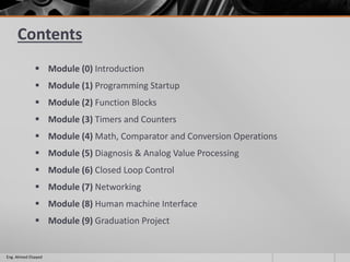
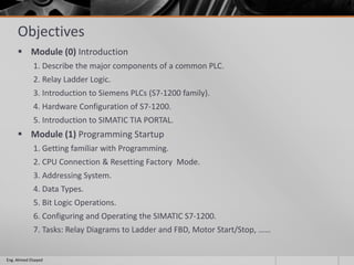
Programmable Logic Controller
S7-1200
SIMATIC TIA PORTAL
Eng. Ahmed Elsayed
Contents
 Module (0) Introduction
 Module (1) Programming Startup
 Module (2) Function Blocks
 Module (3) Timers and Counters
 Module (4) Math, Comparator and Conversion Operations
 Module (5) Diagnosis & Analog Value Processing
 Module (6) Closed Loop Control
 Module (7) Networking
 Module (8) Human machine Interface
 Module (9) Graduation Project
Eng. Ahmed Elsayed
Objectives
 Module (0) Introduction
1. Describe the major components of a common PLC.
2. Relay Ladder Logic.
3. Introduction to Siemens PLCs (S7-1200 family).
4. Hardware Configuration of S7-1200.
5. Introduction to SIMATIC TIA PORTAL.
 Module (1) Programming Startup
1. Getting familiar with Programming.
2. CPU Connection & Resetting Factory Mode.
3. Addressing System.
4. Data Types.
5. Bit Logic Operations.
6. Configuring and Operating the SIMATIC S7-1200.
7. Tasks: Relay Diagrams to Ladder and FBD, Motor Start/Stop, ……
Eng. Ahmed Elsayed
 Module (2) Function Blocks
1. Types of Blocks
2. Linear Programming
3. Structured Programming
4. User Blocks
Organization Blocks, Functions, Function Blocks, Data Blocks
5. Set/Reset Operation
6. Tasks: Stamping System, Belt Control.
 Module (3) Timers & Counters
1. Types of Timers.
2. Types of Counters.
3. Operation of each type.
4. Tasks: Practical Start/Stop Motor, Practical Stamping Machine, Production Line.
Eng. Ahmed Elsayed
 Module (4) Math, Comparator and Conversion Operations
1. Math Operations
2. Comparator Operations
3. Conversion Operations
 Module (5) Diagnosis & Analog Value Processing
 Diagnosis.
1. Open Project Online
2. Device Diagnosis
3. Offline/Online Comparison
4. Monitoring, Controlling and Forcing Variables
 Analog Value Processing.
1. Analog Signals.
2. Reading/Writing Analog Values.
3. Scaling / Un-scaling
4. Task: Tank Level Control.
Eng. Ahmed Elsayed
 Module (6) Closed Loop Control
1.Fundamental of Closed Loop Control.
2.PID in SIMTIC.
3.Tasks: Water Level and Temperature Control.
 Module (7) Networking
1.Networking Basics.
2.Adding another Controller to the Network
3.Communication Blocks.
4.Tasks:
a. Programming for 1st Controller: Conveyer Control.
b. Programming for 2nd Controller: Conveyer Data Logging.
c. Programming of Communication Blocks.
d. Final Project.
Eng. Ahmed Elsayed
 Module (8) Human Machine Interface
1.Display Data on HMI Screens.
2.Sending Data from HMI Screens.
 Module (9) Graduation Project
Eng. Ahmed Elsayed
Module (0) Introduction
1.What is the word “PLC”?
2.The major components of a common PLC.
3.Basic Definitions.
4.Relay Ladder Logic.
5.Introduction to Siemens PLCs (S7-1200 family).
6.Hardware Configuration of S7-1200.
7.Introduction to SIMATIC TIA PORTAL.
Eng. Ahmed Elsayed
What is meant by PLC?
 PLC is an abbreviation for “Programmable Logic Control”.
 It is simply a special computer device used for industrial control systems.
Eng. Ahmed Elsayed
Advantages of PLCs
 Less wiring.
 Wiring between devices and relay contacts are done in the PLC program.
 Easier and faster to make changes.
 Trouble shooting aids make programming easier and reduce downtime.
 Reliable components make these likely to operate for years before failure.
Eng. Ahmed Elsayed
PLC like any PC, consists of:
1. Central Processing Unit.
2. Input/Output (I/O) interface system.
Eng. Ahmed Elsayed
 The central processing unit (CPU) governs all PLC activities.
 The following three components form the CPU:
1. The Processor.
2. The Memory System.
3. The System Power Supply.
Eng. Ahmed Elsayed
Final Block Diagram of CPU interacting with I/Os
Eng. Ahmed Elsayed
Functional interaction of a PLC system
Eng. Ahmed Elsayed
The major components of a common PLC.
Eng. Ahmed Elsayed
Physical Components
Eng. Ahmed Elsayed
Power Supply (PS)
A separate power source for a PLC that converts the standard incoming
220VAC to the low voltage DC that the CPU requires, around 24V or 5V.
General Advantages of Primary PS
- stabilized output voltage.
- high efficiency.
- compact design.
Main Advantages
- Disconnect automatically if short circuit or over-current occurred.
- Return a fault signal if short circuit or over-current occurred.
Eng. Ahmed Elsayed
Central Processing Unit (CPU)
The brain of the whole PLC is the CPU module.
This module typically lives in the slot beside the power supply.
The CPU consists of
a microprocessor, memory chip and
other integrated circuits to control logic,
monitoring and communications.
The CPU has different operating modes,
In programming mode it accepts the
downloaded logic from a PC.
The CPU is then placed in run mode so
that it can execute the program and
operate the process.
Eng. Ahmed Elsayed
I/O System
The I/O system provides the physical connection between the equipment and the
PLC.
Provides signal conversion and isolation between the internal logic- level signals
inside the PLC and the field’s high level signal.
Input modules converts signals from discrete or analog input devices to logic levels
acceptable to PLC’s processor.
Discrete Input (digital input), is an input that is either ON or OFF are connected to
the PLC digital input.
Analog Input, is an input signal that has a continuous signal.
Output modules converts signal from the processor to levels capable of driving the
connected discrete or analog output devices.
Discrete Output(digital output), is an output that is either ON or OFF are connected
to the PLC digital input. (Contact or Transistor)
An analog output, is an output signal that has a continuous signal. Typical outputs
may vary from 0 to 20mA, 4 to 20mA or 0 to10V.
Eng. Ahmed Elsayed
Discrete input
 AC/DC INPUTS
Eng. Ahmed Elsayed
Physical Wiring in Field
Eng. Ahmed Elsayed
AC input module DC input module
 DC INPUTS (SINK/SOURCE)
Eng. Ahmed Elsayed
Sinking input module/sourcing
input device
Sourcing input module/sinking
input device
Field device connections for a sink/source DC input module
Eng. Ahmed Elsayed
Analog Input
Eng. Ahmed Elsayed
Physical Wiring in Field
Eng. Ahmed Elsayed
Discrete Output
 AC Output
Eng. Ahmed Elsayed
 Logic 1– ON (“Switch” Closed)
 Logic 0– OFF (“Switch” Open)
Physical Wiring in Field
Eng. Ahmed Elsayed
 DC Output
Eng. Ahmed Elsayed
Analog Output
Eng. Ahmed Elsayed
Physical Wiring in Field
Eng. Ahmed Elsayed
Rack
The rack is the component that holds everything together.
Depending on the needs of the control system it can be ordered in different
sizes to hold more modules.
Eng. Ahmed Elsayed
Addressing on Rack
Eng. Ahmed Elsayed
Case Study
Process Control System (Tank Control System)
Eng. Ahmed Elsayed
 Control System
Eng. Ahmed Elsayed
SP: Set Point
PV: Process Variable
E: Error
CV: Control Variable
Controller: Control Technique implemented in PLC.
Process: Our Tank Control System (Temperature).
 Actual Control System
Eng. Ahmed Elsayed
Eng. Ahmed Elsayed
Introduction to Siemens PLCs (S7-1200 family)
Eng. Ahmed Elsayed
Family of S7-1200
1. CPU 1211
2. CPU 1212
3. CPU 1214
Eng. Ahmed Elsayed
AC/DC/RLY DC/DC/RLY DC/DC/DC
1. Type of Supply (DC/AC).
2. Type of input signal.
3. Type of Output; DC means the out put will be only DC via transistor
RLY means the output may be DC or AC via relay
Supply/Input/Output
1) Power Connector.
2) I/Os Wiring Connectors.
3) I/Os Status LEDs.
4) PROFINET Connector.
Eng. Ahmed Elsayed
Features of S7-1200
 controller with integrated PROFINET interface for communication
with programming device, HMI or other SIMATIC controllers.
 powerful, integrated technology functions such as counting,
measuring, closed-loop control, and motion control integrated digital
and analog inputs/outputs
 signal boards for direct use in a controller
 signal modules for expansion of controllers by input/output channels
 communication modules for expansion of controllers by
communications interfaces
 accessories, e.g. power supply, switch module or SIMATIC Memory
Card
Eng. Ahmed Elsayed
Communication with Programming device
Eng. Ahmed Elsayed
Eng. Ahmed Elsayed
Architecture Layout
Eng. Ahmed Elsayed
Addressing System
 Input
Eng. Ahmed Elsayed
 Output
Introduction to SIMATIC TIA PORTAL
 STEP7 is the Programming Software of Programmable Logic Controller (PLC)
of the SIMATIC S7 family of Siemens.
 TIA is an abbreviation for “Totally Integrated Automation”
 TIA is a strategy (architecture) in the automation technology, which defines
the interaction of extensive single components, tool (SW) and the services
(spare part service, etc.) to achieve an Automation solution.
 The interaction performs integration across the four automation levels of
the automation pyramid:
1. Management level
2. Operator’s level
3. Controller’s level
4. Field level
Eng. Ahmed Elsayed
Eng. Ahmed Elsayed
Moving to TIA Software !
Eng. Ahmed Elsayed

Programmable logic controller - Siemens S7-1200

  • 1.
    Programmable Logic Controller S7-1200 SIMATICTIA PORTAL Eng. Ahmed Elsayed
  • 2.
    Contents  Module (0)Introduction  Module (1) Programming Startup  Module (2) Function Blocks  Module (3) Timers and Counters  Module (4) Math, Comparator and Conversion Operations  Module (5) Diagnosis & Analog Value Processing  Module (6) Closed Loop Control  Module (7) Networking  Module (8) Human machine Interface  Module (9) Graduation Project Eng. Ahmed Elsayed
  • 3.
    Objectives  Module (0)Introduction 1. Describe the major components of a common PLC. 2. Relay Ladder Logic. 3. Introduction to Siemens PLCs (S7-1200 family). 4. Hardware Configuration of S7-1200. 5. Introduction to SIMATIC TIA PORTAL.  Module (1) Programming Startup 1. Getting familiar with Programming. 2. CPU Connection & Resetting Factory Mode. 3. Addressing System. 4. Data Types. 5. Bit Logic Operations. 6. Configuring and Operating the SIMATIC S7-1200. 7. Tasks: Relay Diagrams to Ladder and FBD, Motor Start/Stop, …… Eng. Ahmed Elsayed
  • 4.
     Module (2)Function Blocks 1. Types of Blocks 2. Linear Programming 3. Structured Programming 4. User Blocks Organization Blocks, Functions, Function Blocks, Data Blocks 5. Set/Reset Operation 6. Tasks: Stamping System, Belt Control.  Module (3) Timers & Counters 1. Types of Timers. 2. Types of Counters. 3. Operation of each type. 4. Tasks: Practical Start/Stop Motor, Practical Stamping Machine, Production Line. Eng. Ahmed Elsayed
  • 5.
     Module (4)Math, Comparator and Conversion Operations 1. Math Operations 2. Comparator Operations 3. Conversion Operations  Module (5) Diagnosis & Analog Value Processing  Diagnosis. 1. Open Project Online 2. Device Diagnosis 3. Offline/Online Comparison 4. Monitoring, Controlling and Forcing Variables  Analog Value Processing. 1. Analog Signals. 2. Reading/Writing Analog Values. 3. Scaling / Un-scaling 4. Task: Tank Level Control. Eng. Ahmed Elsayed
  • 6.
     Module (6)Closed Loop Control 1.Fundamental of Closed Loop Control. 2.PID in SIMTIC. 3.Tasks: Water Level and Temperature Control.  Module (7) Networking 1.Networking Basics. 2.Adding another Controller to the Network 3.Communication Blocks. 4.Tasks: a. Programming for 1st Controller: Conveyer Control. b. Programming for 2nd Controller: Conveyer Data Logging. c. Programming of Communication Blocks. d. Final Project. Eng. Ahmed Elsayed
  • 7.
     Module (8)Human Machine Interface 1.Display Data on HMI Screens. 2.Sending Data from HMI Screens.  Module (9) Graduation Project Eng. Ahmed Elsayed
  • 8.
    Module (0) Introduction 1.Whatis the word “PLC”? 2.The major components of a common PLC. 3.Basic Definitions. 4.Relay Ladder Logic. 5.Introduction to Siemens PLCs (S7-1200 family). 6.Hardware Configuration of S7-1200. 7.Introduction to SIMATIC TIA PORTAL. Eng. Ahmed Elsayed
  • 9.
    What is meantby PLC?  PLC is an abbreviation for “Programmable Logic Control”.  It is simply a special computer device used for industrial control systems. Eng. Ahmed Elsayed
  • 10.
    Advantages of PLCs Less wiring.  Wiring between devices and relay contacts are done in the PLC program.  Easier and faster to make changes.  Trouble shooting aids make programming easier and reduce downtime.  Reliable components make these likely to operate for years before failure. Eng. Ahmed Elsayed
  • 11.
    PLC like anyPC, consists of: 1. Central Processing Unit. 2. Input/Output (I/O) interface system. Eng. Ahmed Elsayed
  • 12.
     The centralprocessing unit (CPU) governs all PLC activities.  The following three components form the CPU: 1. The Processor. 2. The Memory System. 3. The System Power Supply. Eng. Ahmed Elsayed
  • 13.
    Final Block Diagramof CPU interacting with I/Os Eng. Ahmed Elsayed
  • 14.
    Functional interaction ofa PLC system Eng. Ahmed Elsayed
  • 15.
    The major componentsof a common PLC. Eng. Ahmed Elsayed
  • 16.
  • 17.
    Power Supply (PS) Aseparate power source for a PLC that converts the standard incoming 220VAC to the low voltage DC that the CPU requires, around 24V or 5V. General Advantages of Primary PS - stabilized output voltage. - high efficiency. - compact design. Main Advantages - Disconnect automatically if short circuit or over-current occurred. - Return a fault signal if short circuit or over-current occurred. Eng. Ahmed Elsayed
  • 18.
    Central Processing Unit(CPU) The brain of the whole PLC is the CPU module. This module typically lives in the slot beside the power supply. The CPU consists of a microprocessor, memory chip and other integrated circuits to control logic, monitoring and communications. The CPU has different operating modes, In programming mode it accepts the downloaded logic from a PC. The CPU is then placed in run mode so that it can execute the program and operate the process. Eng. Ahmed Elsayed
  • 19.
    I/O System The I/Osystem provides the physical connection between the equipment and the PLC. Provides signal conversion and isolation between the internal logic- level signals inside the PLC and the field’s high level signal. Input modules converts signals from discrete or analog input devices to logic levels acceptable to PLC’s processor. Discrete Input (digital input), is an input that is either ON or OFF are connected to the PLC digital input. Analog Input, is an input signal that has a continuous signal. Output modules converts signal from the processor to levels capable of driving the connected discrete or analog output devices. Discrete Output(digital output), is an output that is either ON or OFF are connected to the PLC digital input. (Contact or Transistor) An analog output, is an output signal that has a continuous signal. Typical outputs may vary from 0 to 20mA, 4 to 20mA or 0 to10V. Eng. Ahmed Elsayed
  • 20.
    Discrete input  AC/DCINPUTS Eng. Ahmed Elsayed
  • 21.
    Physical Wiring inField Eng. Ahmed Elsayed AC input module DC input module
  • 22.
     DC INPUTS(SINK/SOURCE) Eng. Ahmed Elsayed Sinking input module/sourcing input device Sourcing input module/sinking input device
  • 23.
    Field device connectionsfor a sink/source DC input module Eng. Ahmed Elsayed
  • 24.
  • 25.
    Physical Wiring inField Eng. Ahmed Elsayed
  • 26.
    Discrete Output  ACOutput Eng. Ahmed Elsayed  Logic 1– ON (“Switch” Closed)  Logic 0– OFF (“Switch” Open)
  • 27.
    Physical Wiring inField Eng. Ahmed Elsayed
  • 28.
     DC Output Eng.Ahmed Elsayed
  • 29.
  • 30.
    Physical Wiring inField Eng. Ahmed Elsayed
  • 31.
    Rack The rack isthe component that holds everything together. Depending on the needs of the control system it can be ordered in different sizes to hold more modules. Eng. Ahmed Elsayed
  • 32.
  • 33.
    Case Study Process ControlSystem (Tank Control System) Eng. Ahmed Elsayed
  • 34.
     Control System Eng.Ahmed Elsayed SP: Set Point PV: Process Variable E: Error CV: Control Variable Controller: Control Technique implemented in PLC. Process: Our Tank Control System (Temperature).
  • 35.
     Actual ControlSystem Eng. Ahmed Elsayed
  • 36.
  • 37.
    Introduction to SiemensPLCs (S7-1200 family) Eng. Ahmed Elsayed
  • 38.
    Family of S7-1200 1.CPU 1211 2. CPU 1212 3. CPU 1214 Eng. Ahmed Elsayed AC/DC/RLY DC/DC/RLY DC/DC/DC 1. Type of Supply (DC/AC). 2. Type of input signal. 3. Type of Output; DC means the out put will be only DC via transistor RLY means the output may be DC or AC via relay Supply/Input/Output
  • 39.
    1) Power Connector. 2)I/Os Wiring Connectors. 3) I/Os Status LEDs. 4) PROFINET Connector. Eng. Ahmed Elsayed
  • 40.
    Features of S7-1200 controller with integrated PROFINET interface for communication with programming device, HMI or other SIMATIC controllers.  powerful, integrated technology functions such as counting, measuring, closed-loop control, and motion control integrated digital and analog inputs/outputs  signal boards for direct use in a controller  signal modules for expansion of controllers by input/output channels  communication modules for expansion of controllers by communications interfaces  accessories, e.g. power supply, switch module or SIMATIC Memory Card Eng. Ahmed Elsayed
  • 41.
    Communication with Programmingdevice Eng. Ahmed Elsayed
  • 42.
  • 43.
  • 44.
    Addressing System  Input Eng.Ahmed Elsayed  Output
  • 45.
    Introduction to SIMATICTIA PORTAL  STEP7 is the Programming Software of Programmable Logic Controller (PLC) of the SIMATIC S7 family of Siemens.  TIA is an abbreviation for “Totally Integrated Automation”  TIA is a strategy (architecture) in the automation technology, which defines the interaction of extensive single components, tool (SW) and the services (spare part service, etc.) to achieve an Automation solution.  The interaction performs integration across the four automation levels of the automation pyramid: 1. Management level 2. Operator’s level 3. Controller’s level 4. Field level Eng. Ahmed Elsayed
  • 46.
  • 47.
    Moving to TIASoftware ! Eng. Ahmed Elsayed