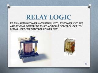
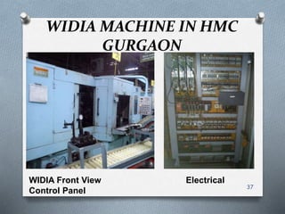
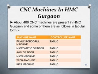
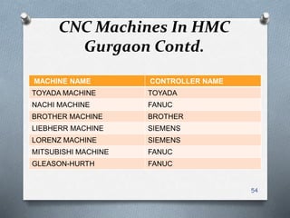
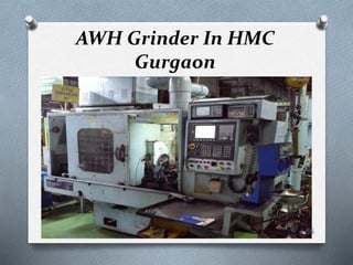
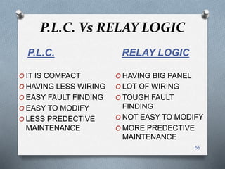
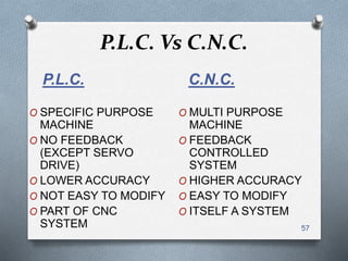
SUMMER
INTERNSHIP
REPORT
1
About Hero Moto Corp
● Hero Moto Corp Ltd., formerly Hero
Honda, is an Indian motorcycle and
scooter manufacturer based in New Delhi, India.
●Hero Honda started in 1984 as a joint venture
between Hero Cycles of India and Honda of Japan.
The company is the largest two wheeler
manufacturer in India.
●The 2006 Forbes 200 Most Respected companies
list has Hero Honda Motors ranked at #108
●It has three plants in Dharuhera Gurgaon and
Haridwar
2
About Hero Moto Corp Contd.
●In 2010, when Honda decided to move out of the
joint venture, Hero Group bought the shares held by
Honda. Subsequently, in August 2011 the company
was renamed Hero MotoCorp with a new corporate
identity
●Brij Mohanlal Munjal is chairman and Pawan
Munjal is MD & CEO of Hero Moto Corp
●The Company has Technical Collaboration with
EVR America and EEE Italy
●As on March 31, 2012 the total numbers of
employees on the records of the Company were
6,106 3
Products
O Passion And it’s variants
O Glamour And Glamour FI
O CBZ Extreme
O Karizma And Karizma ZMR
O Hunk
O Impulse
O Achiever
O Ignitor
O Pleasure
O Maestro
O Splendor And it’s variants
4
Capacity
•Three globally benchmarked facilities, with a
combined installed capacity of 6.35 million units.
•Over 41.7 million two wheelers sold
•60,000 vehicles a month
•125cc motorcycles 75,000 vehicles per month
•17 different products across 100cc, 125cc, 150cc,
225cc and scooter category
•Team Hero comprises 6,106 motivated people
5
Annual Turnover
6
Ten Years Performance
7
Maintenance’s Distribution
Maintenance
DG
House
Utility
Frame
Plant
Engine
Plant
8
Types of Maintenance
Maintenance
Sustain
Activity
Preventive
Maintenance
Breakdown
Maintenance
Kaizen
Activity
Corrective
Maintenance
Maintenance
Prevention
9
Types of Maintenance
Preventive
Maintenance
Time Based
Maintenance
Condition
Based
Maintenance
Breakdown
Maintenance
Planned
Breakdown
Maintenance
Emergency
Maintenance
10
Engine Plant’s Distribution
ENGINE
PLANT
ALUMUNIUM
PHASE
CRANK
CASE
CYLINDER
HEAD
STEEL
PHASE
CRANK
SHAFT
CYLINDER
CONRODS
GEAR
SECTION
GEARS
SHAFTS
HEAT
TREATMENT
11
RELAY LOGIC
IT IS HAVING POWER & CONTROL CKT., BY POWER CKT. WE
ARE GIVING POWER TO THAT MOTOR & CONTROL CKT. IS
BEING USED TO CONTROL POWER CKT.
12
Basic Relays
● A relay is an electronic control switch used to open
or close a mechanical contact whenever a voltage
is applied to its coil.
●A switch whose operation is activated by an
electromagnet is called a "relay"
13
Basic Relays
● A basic relay usually contains two sets of contacts,
normally open and normally closed. The schematic
will show the normal contact position for a
de-energized coil
14
PUSH BUTTON
■ A Push Button is a simple switch mechanism for controlling
some aspect of a machine or process. It’s examples are Start
Push Button, Stop Push Button.
■ Start Push Button is used to start any machine’s process.
Normally, it is held open by a spring and thus NO(Normally
Open) by nature.
■ Stop Push Button is used to stop any machine’s
process.Normally,it is held closed by a spring and thus
NC(Normally Closed) by nature.
15
Proximity Switch
■ A Proximity Sensor is a sensor able to detect the presence of
nearby objects without any physical contact.
■ A proximity sensor often emits an electromagnetic field or a
beam of electromagnetic radiation (infrared, for instance), and
looks for changes in the field or return signal. The object being
sensed is often referred to as the proximity sensor's target. The
maximum distance that this sensor can detect is defined "nominal
range".
■ Types :- Capacitive, Eddy-current, Inductive, Photocell, Radar,
Sonar
■ Applications :- Parktronic, Roller coasters, Conveyor systems,
Mobile devices
16
Limit Switch
■ A limit switch is an electromechanical device that consists of an actuator
mechanically linked to a set of contacts. When an object comes into contact
with the actuator, the device operates the contacts to make or break an
electrical connection.
■ Limit switches are electro mechanical switches.
■Types :- lever, roller plunger, and whisker
■ Applications :- A lathe will have limit switches to identify maximum limits
for machine parts or to provide a known reference point for incremental
motions and in roller coaster’s operation.
17
Timer Switch
■ A timer switch is a timer that operates an
electric switch controlled by the timing mechanism.
■ The mechanism may be mechanical or electronic,
with semiconductor timing circuitry and switching devices and no
moving parts or electromechanical.
■ Applications :- In CNC/PLC machines for timed control
lubricant flow, switching any device on or off at desired time and
thus saving electrical energy like street lightining,oven,washing
machines.
18
Motor Control Circuitry
19
Control
Voltage
Return
Three Phase
Line
Main Contacts
Auxillary
Contacts
Contactor Coil
M
Motor
Contactor START
STOP
Control
Voltage
Source
L1 L2 L3
DOL Starter Mechanism
■ In DOL method the motor is connected by means of
starter across the full supply voltage.
■ On pressing the START push button the contactor
coil is energized from two line conductors as shown.
■ Following the three main contacts and the auxiliary
contact is closed and the motor is thus connected to
supply.
■ When the pressure on START push button is
released, it moves back under spring action but the coil
remain energized through auxiliary contact and thus it
called as hold-on-contact.
■ When STOP push button is pressed ,the supply
through the contactor coil is disconnected or is de-
energized.
■ Thus the main contacts and auxiliary contact are
open and the supply to motor is disconnected and thus
20
Relay Logic Based Machine
in HMC Gurgaon
STD. GRINDER
Grinder front view Electrical Control
Panel
21
22
PLC-Definition
– PLC: (Programmable Logic Controller) An
industrial control device developed to accept
contact closure inputs and to provide outputs
that drive relay coils.
• The device may be re-programmed with code relating
inputs to outputs
• Modern PLCs may allow analog input/output and may
support high level language functions (C, C++, BASIC)
• Programming logic includes simple logic, timing
functions counting functions, sequences, and may
include complex algorithms (eg. PID)
• Examples: Allen-Bradley, Mitsubishi, Messung,etc.
23
CONTENTS OF P.L.C.
POWER
SUPPLY
CENTRAL
PROCESSING
UNIT
INPUT
CARD
I0
INPUT
CARD
I1
OUTPUT
CARD
O2
OUTPUT
CARD
O3
24
WORKING OF
P.L.C.
FROM M/C I/P CARD C.P.U.
O/P CARD TO M/C
25
Power Supply
A power supply is needed to provide power to the PLC and
any other modules. Power supplies come in various
forms:
• Power supply modules that fit into one of the slots in a chassis
• External power supplies that mount to the outside of a chassis
• Stand alone power supplies that connect to the PLC or I/O
through a power cable
• Embedded power supplies that come as part of the PLC block.
26
Central Processing Unit
Processor, Controller, or CPU
• Stores the control program and data in its memory
• Reads the status of connected input devices
• Executes the control program
• Commands connected outputs to change state based on program
execution
– For example: Turn a light on, start a fan, adjust a speed, or temperature
27
Input Modules
●Input modules interface directly to devices
such as switches and temperature sensors.
●Input modules convert many different types
of electrical signals such as 120VAC, 24VDC,
or 4-20mA, to signals which the controller can
understand.
●Input Modules convert real world voltage
and currents to signals that PLC can
understand. Input Modules include both digital
and analog modules. 28
29
Output Modules
•Output modules interface directly to devices
such as motor starters and lights.
•Output modules take digital signals from the
PLC and convert them to electrical signals such
as 24VDC and 4 mA that field devices can
understand.
•Output modules take a signal from a PLC and
convert it to a signal that a field device needs to
operate. Since there are different types of output
devices, there is a wide variety of output cards
available, including both digital and analog
cards.
30
31
COMMON INPUTS &
OUTPUTS
■ INPUTS :- LIMIT SWITCH ,
PROXIMITY SWITCH , PUSH
BUTTONS , PRESSURE SWITCH
ETC.
■ OUTPUTS :- SOL. COIL ,
CONTACTOR COIL , CONTROL
RELAYS , L.E.D.s ETC.
32
PLC Control Panel
33
PLC’S Programming
Every PLC has associated programming software that
allows the user to enter a program into the PLC.
•Software used today is Windows based, and can be run
on any PC.
•Different products may require different software: PLC5,
SLC, and Control Logic each require their own
programming software
•Before a PLC can perform any control task, it must be
programmed to do so. The most popular language used
to program a PLC is ladder logic.
•Other languages are Function Block, Structural Text, High
level languages, Sequential Function Chart.
34
Example of Ladder Logic
35
PLC Machines in HMC
Gurgaon
● About 200 PLC machines are present in HMC
Gurgaon and some of them are as follows in tabular
form :-
MACHINE NAME CONTROLLER NAME
Widia Machine Messung, Mitsubishi
Leak Testing Machine Mitsubishi
Washing Machine Messung, Mitsubishi
HMT Machine Messung
Mico Machine Messung
Honing Machine Mitsubishi
36
WIDIA MACHINE IN HMC
GURGAON
WIDIA Front View Electrical
Control Panel
37
38
NC & CNC
Numerical control (NC) is a method of automatically
operating a manufacturing machine based on a code
letters, numbers and special characters.
The numerical data required to produce a part is
provided to a machine in the form of program, called part
program or CNC (computer numerical control).
The program is translated into the appropriate electrical
signals for input to motors that run the machine.
A CNC machine is an numerical control machine with the
added feature of an on board computer. The computer is
referred to as the machine control unit (MCU).
39
CNC System Elements
A typical CNC system consists of the following six
elements
 Part program
 Program input device
 Machine control unit
 Drive system
 Machine tool
 Feedback system
40
Types Of CNC Machines
41
Tool Movements
Point To Point Continuous
Movement
42
Loop System For Controlling
Tool
43
Application Of CNC
Machines
● Cutting
● Milling
● Boring
● Spinning
● Drilling
● Welding
● Sewing
44
Electrical Panel Of CNC
Machine
45
Servo Drive
O A servo drive is a special electronic amplifier used to power
electric servomechanisms.
O A servo drive monitors the feedback signal from the servomechanism
and continually adjusts for deviation from expected behavior.
O A servo drive receives a command signal from a control system,
amplifies the signal, and transmits electric current to a servo motor in
order to produce motion proportional to the command signal.
O Servo systems can be used in CNC machining, factory automation, and
robotics, among other uses.
46
Contactor
● A contactor is an electrically controlled switch used for switching a power
circuit, similar to a relay except with higher current ratings.
● A contactor is controlled by a circuit which has a much lower power level
than the switched circuit.
● Contactors range from those having a breaking current of several
amperes to thousands of amperes and 24 V DC to many kilovolts.
● Contactors are used to control electric
motors, lighting, heating, capacitor banks, thermal evaporators, and other
electrical loads.
47
MCB & MPCB
■ Miniature circuit breakers (MCBs) are fitted as protection units in place of
fuses. They have the advantage that they can be manually reset without having
to replace wire as in the case of the traditional fuse. The MCB tripping is an
indication either that the circuit has been overloaded or that a short circuit has
occurred somewhere in the system.
■ The Motor Protection Circuit Breakers (MPCBs) provide short circuit protection,
overload protection, and motor disconnect functions. The MPCBs may be
combined with a magnetic contactor to provide 2 component combination
starters and with the addition of an overload relay. They generally provide
contacts to indicate position (Trip, Not Tripped).
◄ MCB
MPCB ►
48
Relays
O A relay is an electrically operated switch. Many relays use an
electromagnet to operate a switching mechanism
mechanically but other operating principles are also used.
O Relays are used where it is necessary to control a circuit by
a low-power signal (with complete electrical isolation
between control and controlled circuits), or where several
circuits must be controlled by one signal.
O Relays are used to protect electrical circuits from overload
or faults.
49
SMPS
►A switched-mode power supply (switching-mode power supply,
SMPS, or switcher) is an electronic power supply that incorporates a
switching regulator to convert electrical power efficiently.
► SMPS transfers power from a source, like mains power, to a load.
►Voltage regulation is achieved by varying the ratio of on-to-off time
►This higher power conversion efficiency is an important advantage of
a switched-mode power supply.
SMPS are smaller in size and lighter in weight.
50
CNC Machine’s Basic
Programming
Part programming contains geometric data about the part and motion
information to move the cutting tool with respect to the work piece.
Basically, the machine receives instructions as a sequence of blocks
containing commands to set machine parameters; speed, feed and
other relevant information.
A block is equivalent to a line of codes in a part program.
An example of CNC Machine programming as given below :-
51
Various Codes
● Preparatory command (G code)
The G codes prepare the MCU for a given operation,
typically involving a cutter motion.
Ex :- G00 rapid motion, point-to-point positioning
G33 thread cutting
● Miscellaneous commands (M code)
Ex :- M00 program stop , M06 tool change
● Feed commands (F code)
Used to specify the cutter feed rates in inch per minute
● Speed commands (S code)
Used to specify the spindle speed in rpm.
● Tool commands (T code)
Specifies which tool to be used, machines with automatic
tool changer. 52
CNC Machines In HMC
Gurgaon
► About 400 CNC machines are present in HMC
Gurgaon and some of them are as follows in tabular
form :-
MACHINE NAME CONTROLLER NAME
FANUC ROBODRILL
MACHINE
FANUC
MICROMATIC GRINDER FANUC
AWH GRINDER FANUC
MICO MACHINE FANUC
WIDIA MACHINE FANUC
KIRA MACHINE FANUC 53
CNC Machines In HMC
Gurgaon Contd.
MACHINE NAME CONTROLLER NAME
TOYADA MACHINE TOYADA
NACHI MACHINE FANUC
BROTHER MACHINE BROTHER
LIEBHERR MACHINE SIEMENS
LORENZ MACHINE SIEMENS
MITSUBISHI MACHINE FANUC
GLEASON-HURTH FANUC
54
AWH Grinder In HMC
Gurgaon
55
P.L.C. Vs RELAY LOGIC
P.L.C.
O IT IS COMPACT
O HAVING LESS WIRING
O EASY FAULT FINDING
O EASY TO MODIFY
O LESS PREDECTIVE
MAINTENANCE
RELAY LOGIC
O HAVING BIG PANEL
O LOT OF WIRING
O TOUGH FAULT
FINDING
O NOT EASY TO MODIFY
O MORE PREDECTIVE
MAINTENANCE
56
P.L.C. Vs C.N.C.
P.L.C.
O SPECIFIC PURPOSE
MACHINE
O NO FEEDBACK
(EXCEPT SERVO
DRIVE)
O LOWER ACCURACY
O NOT EASY TO MODIFY
O PART OF CNC
SYSTEM
C.N.C.
O MULTI PURPOSE
MACHINE
O FEEDBACK
CONTROLLED
SYSTEM
O HIGHER ACCURACY
O EASY TO MODIFY
O ITSELF A SYSTEM
57
THANK
YOU
MADE BY :-
AMRITANSHU KUMAR
58

AMRITANSHU KUMAR_SUMMER INTERNSHIP

  • 1.
  • 2.
    About Hero MotoCorp ● Hero Moto Corp Ltd., formerly Hero Honda, is an Indian motorcycle and scooter manufacturer based in New Delhi, India. ●Hero Honda started in 1984 as a joint venture between Hero Cycles of India and Honda of Japan. The company is the largest two wheeler manufacturer in India. ●The 2006 Forbes 200 Most Respected companies list has Hero Honda Motors ranked at #108 ●It has three plants in Dharuhera Gurgaon and Haridwar 2
  • 3.
    About Hero MotoCorp Contd. ●In 2010, when Honda decided to move out of the joint venture, Hero Group bought the shares held by Honda. Subsequently, in August 2011 the company was renamed Hero MotoCorp with a new corporate identity ●Brij Mohanlal Munjal is chairman and Pawan Munjal is MD & CEO of Hero Moto Corp ●The Company has Technical Collaboration with EVR America and EEE Italy ●As on March 31, 2012 the total numbers of employees on the records of the Company were 6,106 3
  • 4.
    Products O Passion Andit’s variants O Glamour And Glamour FI O CBZ Extreme O Karizma And Karizma ZMR O Hunk O Impulse O Achiever O Ignitor O Pleasure O Maestro O Splendor And it’s variants 4
  • 5.
    Capacity •Three globally benchmarkedfacilities, with a combined installed capacity of 6.35 million units. •Over 41.7 million two wheelers sold •60,000 vehicles a month •125cc motorcycles 75,000 vehicles per month •17 different products across 100cc, 125cc, 150cc, 225cc and scooter category •Team Hero comprises 6,106 motivated people 5
  • 6.
  • 7.
  • 8.
  • 9.
  • 10.
    Types of Maintenance Preventive Maintenance TimeBased Maintenance Condition Based Maintenance Breakdown Maintenance Planned Breakdown Maintenance Emergency Maintenance 10
  • 11.
  • 12.
    RELAY LOGIC IT ISHAVING POWER & CONTROL CKT., BY POWER CKT. WE ARE GIVING POWER TO THAT MOTOR & CONTROL CKT. IS BEING USED TO CONTROL POWER CKT. 12
  • 13.
    Basic Relays ● Arelay is an electronic control switch used to open or close a mechanical contact whenever a voltage is applied to its coil. ●A switch whose operation is activated by an electromagnet is called a "relay" 13
  • 14.
    Basic Relays ● Abasic relay usually contains two sets of contacts, normally open and normally closed. The schematic will show the normal contact position for a de-energized coil 14
  • 15.
    PUSH BUTTON ■ APush Button is a simple switch mechanism for controlling some aspect of a machine or process. It’s examples are Start Push Button, Stop Push Button. ■ Start Push Button is used to start any machine’s process. Normally, it is held open by a spring and thus NO(Normally Open) by nature. ■ Stop Push Button is used to stop any machine’s process.Normally,it is held closed by a spring and thus NC(Normally Closed) by nature. 15
  • 16.
    Proximity Switch ■ AProximity Sensor is a sensor able to detect the presence of nearby objects without any physical contact. ■ A proximity sensor often emits an electromagnetic field or a beam of electromagnetic radiation (infrared, for instance), and looks for changes in the field or return signal. The object being sensed is often referred to as the proximity sensor's target. The maximum distance that this sensor can detect is defined "nominal range". ■ Types :- Capacitive, Eddy-current, Inductive, Photocell, Radar, Sonar ■ Applications :- Parktronic, Roller coasters, Conveyor systems, Mobile devices 16
  • 17.
    Limit Switch ■ Alimit switch is an electromechanical device that consists of an actuator mechanically linked to a set of contacts. When an object comes into contact with the actuator, the device operates the contacts to make or break an electrical connection. ■ Limit switches are electro mechanical switches. ■Types :- lever, roller plunger, and whisker ■ Applications :- A lathe will have limit switches to identify maximum limits for machine parts or to provide a known reference point for incremental motions and in roller coaster’s operation. 17
  • 18.
    Timer Switch ■ Atimer switch is a timer that operates an electric switch controlled by the timing mechanism. ■ The mechanism may be mechanical or electronic, with semiconductor timing circuitry and switching devices and no moving parts or electromechanical. ■ Applications :- In CNC/PLC machines for timed control lubricant flow, switching any device on or off at desired time and thus saving electrical energy like street lightining,oven,washing machines. 18
  • 19.
    Motor Control Circuitry 19 Control Voltage Return ThreePhase Line Main Contacts Auxillary Contacts Contactor Coil M Motor Contactor START STOP Control Voltage Source L1 L2 L3
  • 20.
    DOL Starter Mechanism ■In DOL method the motor is connected by means of starter across the full supply voltage. ■ On pressing the START push button the contactor coil is energized from two line conductors as shown. ■ Following the three main contacts and the auxiliary contact is closed and the motor is thus connected to supply. ■ When the pressure on START push button is released, it moves back under spring action but the coil remain energized through auxiliary contact and thus it called as hold-on-contact. ■ When STOP push button is pressed ,the supply through the contactor coil is disconnected or is de- energized. ■ Thus the main contacts and auxiliary contact are open and the supply to motor is disconnected and thus 20
  • 21.
    Relay Logic BasedMachine in HMC Gurgaon STD. GRINDER Grinder front view Electrical Control Panel 21
  • 22.
  • 23.
    PLC-Definition – PLC: (ProgrammableLogic Controller) An industrial control device developed to accept contact closure inputs and to provide outputs that drive relay coils. • The device may be re-programmed with code relating inputs to outputs • Modern PLCs may allow analog input/output and may support high level language functions (C, C++, BASIC) • Programming logic includes simple logic, timing functions counting functions, sequences, and may include complex algorithms (eg. PID) • Examples: Allen-Bradley, Mitsubishi, Messung,etc. 23
  • 24.
  • 25.
    WORKING OF P.L.C. FROM M/CI/P CARD C.P.U. O/P CARD TO M/C 25
  • 26.
    Power Supply A powersupply is needed to provide power to the PLC and any other modules. Power supplies come in various forms: • Power supply modules that fit into one of the slots in a chassis • External power supplies that mount to the outside of a chassis • Stand alone power supplies that connect to the PLC or I/O through a power cable • Embedded power supplies that come as part of the PLC block. 26
  • 27.
    Central Processing Unit Processor,Controller, or CPU • Stores the control program and data in its memory • Reads the status of connected input devices • Executes the control program • Commands connected outputs to change state based on program execution – For example: Turn a light on, start a fan, adjust a speed, or temperature 27
  • 28.
    Input Modules ●Input modulesinterface directly to devices such as switches and temperature sensors. ●Input modules convert many different types of electrical signals such as 120VAC, 24VDC, or 4-20mA, to signals which the controller can understand. ●Input Modules convert real world voltage and currents to signals that PLC can understand. Input Modules include both digital and analog modules. 28
  • 29.
  • 30.
    Output Modules •Output modulesinterface directly to devices such as motor starters and lights. •Output modules take digital signals from the PLC and convert them to electrical signals such as 24VDC and 4 mA that field devices can understand. •Output modules take a signal from a PLC and convert it to a signal that a field device needs to operate. Since there are different types of output devices, there is a wide variety of output cards available, including both digital and analog cards. 30
  • 31.
  • 32.
    COMMON INPUTS & OUTPUTS ■INPUTS :- LIMIT SWITCH , PROXIMITY SWITCH , PUSH BUTTONS , PRESSURE SWITCH ETC. ■ OUTPUTS :- SOL. COIL , CONTACTOR COIL , CONTROL RELAYS , L.E.D.s ETC. 32
  • 33.
  • 34.
    PLC’S Programming Every PLChas associated programming software that allows the user to enter a program into the PLC. •Software used today is Windows based, and can be run on any PC. •Different products may require different software: PLC5, SLC, and Control Logic each require their own programming software •Before a PLC can perform any control task, it must be programmed to do so. The most popular language used to program a PLC is ladder logic. •Other languages are Function Block, Structural Text, High level languages, Sequential Function Chart. 34
  • 35.
  • 36.
    PLC Machines inHMC Gurgaon ● About 200 PLC machines are present in HMC Gurgaon and some of them are as follows in tabular form :- MACHINE NAME CONTROLLER NAME Widia Machine Messung, Mitsubishi Leak Testing Machine Mitsubishi Washing Machine Messung, Mitsubishi HMT Machine Messung Mico Machine Messung Honing Machine Mitsubishi 36
  • 37.
    WIDIA MACHINE INHMC GURGAON WIDIA Front View Electrical Control Panel 37
  • 38.
  • 39.
    NC & CNC Numericalcontrol (NC) is a method of automatically operating a manufacturing machine based on a code letters, numbers and special characters. The numerical data required to produce a part is provided to a machine in the form of program, called part program or CNC (computer numerical control). The program is translated into the appropriate electrical signals for input to motors that run the machine. A CNC machine is an numerical control machine with the added feature of an on board computer. The computer is referred to as the machine control unit (MCU). 39
  • 40.
    CNC System Elements Atypical CNC system consists of the following six elements  Part program  Program input device  Machine control unit  Drive system  Machine tool  Feedback system 40
  • 41.
    Types Of CNCMachines 41
  • 42.
    Tool Movements Point ToPoint Continuous Movement 42
  • 43.
    Loop System ForControlling Tool 43
  • 44.
    Application Of CNC Machines ●Cutting ● Milling ● Boring ● Spinning ● Drilling ● Welding ● Sewing 44
  • 45.
    Electrical Panel OfCNC Machine 45
  • 46.
    Servo Drive O Aservo drive is a special electronic amplifier used to power electric servomechanisms. O A servo drive monitors the feedback signal from the servomechanism and continually adjusts for deviation from expected behavior. O A servo drive receives a command signal from a control system, amplifies the signal, and transmits electric current to a servo motor in order to produce motion proportional to the command signal. O Servo systems can be used in CNC machining, factory automation, and robotics, among other uses. 46
  • 47.
    Contactor ● A contactoris an electrically controlled switch used for switching a power circuit, similar to a relay except with higher current ratings. ● A contactor is controlled by a circuit which has a much lower power level than the switched circuit. ● Contactors range from those having a breaking current of several amperes to thousands of amperes and 24 V DC to many kilovolts. ● Contactors are used to control electric motors, lighting, heating, capacitor banks, thermal evaporators, and other electrical loads. 47
  • 48.
    MCB & MPCB ■Miniature circuit breakers (MCBs) are fitted as protection units in place of fuses. They have the advantage that they can be manually reset without having to replace wire as in the case of the traditional fuse. The MCB tripping is an indication either that the circuit has been overloaded or that a short circuit has occurred somewhere in the system. ■ The Motor Protection Circuit Breakers (MPCBs) provide short circuit protection, overload protection, and motor disconnect functions. The MPCBs may be combined with a magnetic contactor to provide 2 component combination starters and with the addition of an overload relay. They generally provide contacts to indicate position (Trip, Not Tripped). ◄ MCB MPCB ► 48
  • 49.
    Relays O A relayis an electrically operated switch. Many relays use an electromagnet to operate a switching mechanism mechanically but other operating principles are also used. O Relays are used where it is necessary to control a circuit by a low-power signal (with complete electrical isolation between control and controlled circuits), or where several circuits must be controlled by one signal. O Relays are used to protect electrical circuits from overload or faults. 49
  • 50.
    SMPS ►A switched-mode powersupply (switching-mode power supply, SMPS, or switcher) is an electronic power supply that incorporates a switching regulator to convert electrical power efficiently. ► SMPS transfers power from a source, like mains power, to a load. ►Voltage regulation is achieved by varying the ratio of on-to-off time ►This higher power conversion efficiency is an important advantage of a switched-mode power supply. SMPS are smaller in size and lighter in weight. 50
  • 51.
    CNC Machine’s Basic Programming Partprogramming contains geometric data about the part and motion information to move the cutting tool with respect to the work piece. Basically, the machine receives instructions as a sequence of blocks containing commands to set machine parameters; speed, feed and other relevant information. A block is equivalent to a line of codes in a part program. An example of CNC Machine programming as given below :- 51
  • 52.
    Various Codes ● Preparatorycommand (G code) The G codes prepare the MCU for a given operation, typically involving a cutter motion. Ex :- G00 rapid motion, point-to-point positioning G33 thread cutting ● Miscellaneous commands (M code) Ex :- M00 program stop , M06 tool change ● Feed commands (F code) Used to specify the cutter feed rates in inch per minute ● Speed commands (S code) Used to specify the spindle speed in rpm. ● Tool commands (T code) Specifies which tool to be used, machines with automatic tool changer. 52
  • 53.
    CNC Machines InHMC Gurgaon ► About 400 CNC machines are present in HMC Gurgaon and some of them are as follows in tabular form :- MACHINE NAME CONTROLLER NAME FANUC ROBODRILL MACHINE FANUC MICROMATIC GRINDER FANUC AWH GRINDER FANUC MICO MACHINE FANUC WIDIA MACHINE FANUC KIRA MACHINE FANUC 53
  • 54.
    CNC Machines InHMC Gurgaon Contd. MACHINE NAME CONTROLLER NAME TOYADA MACHINE TOYADA NACHI MACHINE FANUC BROTHER MACHINE BROTHER LIEBHERR MACHINE SIEMENS LORENZ MACHINE SIEMENS MITSUBISHI MACHINE FANUC GLEASON-HURTH FANUC 54
  • 55.
    AWH Grinder InHMC Gurgaon 55
  • 56.
    P.L.C. Vs RELAYLOGIC P.L.C. O IT IS COMPACT O HAVING LESS WIRING O EASY FAULT FINDING O EASY TO MODIFY O LESS PREDECTIVE MAINTENANCE RELAY LOGIC O HAVING BIG PANEL O LOT OF WIRING O TOUGH FAULT FINDING O NOT EASY TO MODIFY O MORE PREDECTIVE MAINTENANCE 56
  • 57.
    P.L.C. Vs C.N.C. P.L.C. OSPECIFIC PURPOSE MACHINE O NO FEEDBACK (EXCEPT SERVO DRIVE) O LOWER ACCURACY O NOT EASY TO MODIFY O PART OF CNC SYSTEM C.N.C. O MULTI PURPOSE MACHINE O FEEDBACK CONTROLLED SYSTEM O HIGHER ACCURACY O EASY TO MODIFY O ITSELF A SYSTEM 57
  • 58.