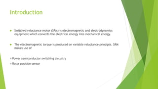
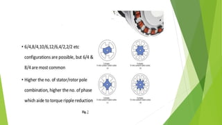
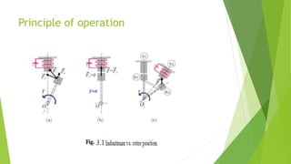
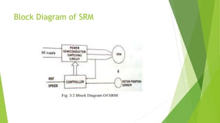
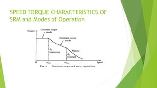
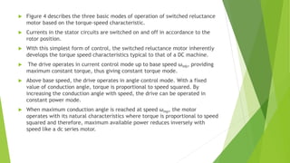
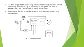
Switched Reluctance
Motor (SRM)
Introduction
 Switched reluctance motor (SRM) is electromagnetic and electrodynamics
equipment which converts the electrical energy into mechanical energy.
 The electromagnetic torque is produced on variable reluctance principle. SRM
makes use of
Power semiconductor switching circuitry
Rotor position sensor
Construction
 The stator is made up of silicon steel stampings with inward projected poles.
The number of poles of the stator can be either an even number or an odd
number.
 Most of the motors available have even number of stator poles (6 or 8).
Principle of operation
Block Diagram of SRM
SPEED TORQUE CHARACTERISTICS OF
SRM and Modes of Operation
 Figure 4 describes the three basic modes of operation of switched reluctance
motor based on the torque-speed characteristic.
 Currents in the stator circuits are switched on and off in accordance to the
rotor position.
 With this simplest form of control, the switched reluctance motor inherently
develops the torque speed characteristics typical to that of a DC machine.
 The drive operates in current control mode up to base speed ωmb, providing
maximum constant torque, thus giving constant torque mode.
 Above base speed, the drive operates in angle control mode. With a fixed
value of conduction angle, torque is proportional to speed squared. By
increasing the conduction angle with speed, the drive can be operated in
constant power mode.
 When maximum conduction angle is reached at speed ωmp, the motor
operates with its natural characteristics where torque is proportional to speed
squared and therefore, maximum available power reduces inversely with
speed like a dc series motor.
 The drive is operated in closed-loop with outer speed loop and inner current
control loop, as shown in Fig. 5. Depending on the speed, the drive is
operated in current control mode or angle control mode.
 Depending on the sign of speed error the drive is operated in motoring or
braking mode.
Torque Equation
 Consider the phase winding excited by a voltage source of voltage v. Then
where i is the current through the phase winding, R the resistance of the phase
winding and ψ the total flux linkage of the phase winding.
Substituting ψ = Li in Eq.3.1
where ωm = rotor speed in radians/second.
 The term ωm i(dL/dθ) is the phase winding back emf e given by the following
equation
The back emf is a function of i, ωm and (dL/dθ). The instantaneous electrical
power input to the machine is given by
where T is the instantaneous value of developed torque.
 The instantaneous power supplied to the machine, vi, is utilized to provide
the following:
 winding heat loss, Ri2
 rate of change of the stored magnetic field energy, d/dt (1/2 Li2)
 the mechanical power output
 From Eqns. (3.7) and (3.8), the motor torque is given by

Switched Reluctance Motor SRM - Introduction

  • 1.
  • 3.
    Introduction  Switched reluctancemotor (SRM) is electromagnetic and electrodynamics equipment which converts the electrical energy into mechanical energy.  The electromagnetic torque is produced on variable reluctance principle. SRM makes use of Power semiconductor switching circuitry Rotor position sensor
  • 4.
    Construction  The statoris made up of silicon steel stampings with inward projected poles. The number of poles of the stator can be either an even number or an odd number.  Most of the motors available have even number of stator poles (6 or 8).
  • 6.
  • 8.
  • 9.
    SPEED TORQUE CHARACTERISTICSOF SRM and Modes of Operation
  • 10.
     Figure 4describes the three basic modes of operation of switched reluctance motor based on the torque-speed characteristic.  Currents in the stator circuits are switched on and off in accordance to the rotor position.  With this simplest form of control, the switched reluctance motor inherently develops the torque speed characteristics typical to that of a DC machine.  The drive operates in current control mode up to base speed ωmb, providing maximum constant torque, thus giving constant torque mode.  Above base speed, the drive operates in angle control mode. With a fixed value of conduction angle, torque is proportional to speed squared. By increasing the conduction angle with speed, the drive can be operated in constant power mode.  When maximum conduction angle is reached at speed ωmp, the motor operates with its natural characteristics where torque is proportional to speed squared and therefore, maximum available power reduces inversely with speed like a dc series motor.
  • 11.
     The driveis operated in closed-loop with outer speed loop and inner current control loop, as shown in Fig. 5. Depending on the speed, the drive is operated in current control mode or angle control mode.  Depending on the sign of speed error the drive is operated in motoring or braking mode.
  • 12.
    Torque Equation  Considerthe phase winding excited by a voltage source of voltage v. Then where i is the current through the phase winding, R the resistance of the phase winding and ψ the total flux linkage of the phase winding. Substituting ψ = Li in Eq.3.1
  • 13.
    where ωm =rotor speed in radians/second.  The term ωm i(dL/dθ) is the phase winding back emf e given by the following equation The back emf is a function of i, ωm and (dL/dθ). The instantaneous electrical power input to the machine is given by
  • 14.
    where T isthe instantaneous value of developed torque.  The instantaneous power supplied to the machine, vi, is utilized to provide the following:  winding heat loss, Ri2  rate of change of the stored magnetic field energy, d/dt (1/2 Li2)  the mechanical power output  From Eqns. (3.7) and (3.8), the motor torque is given by