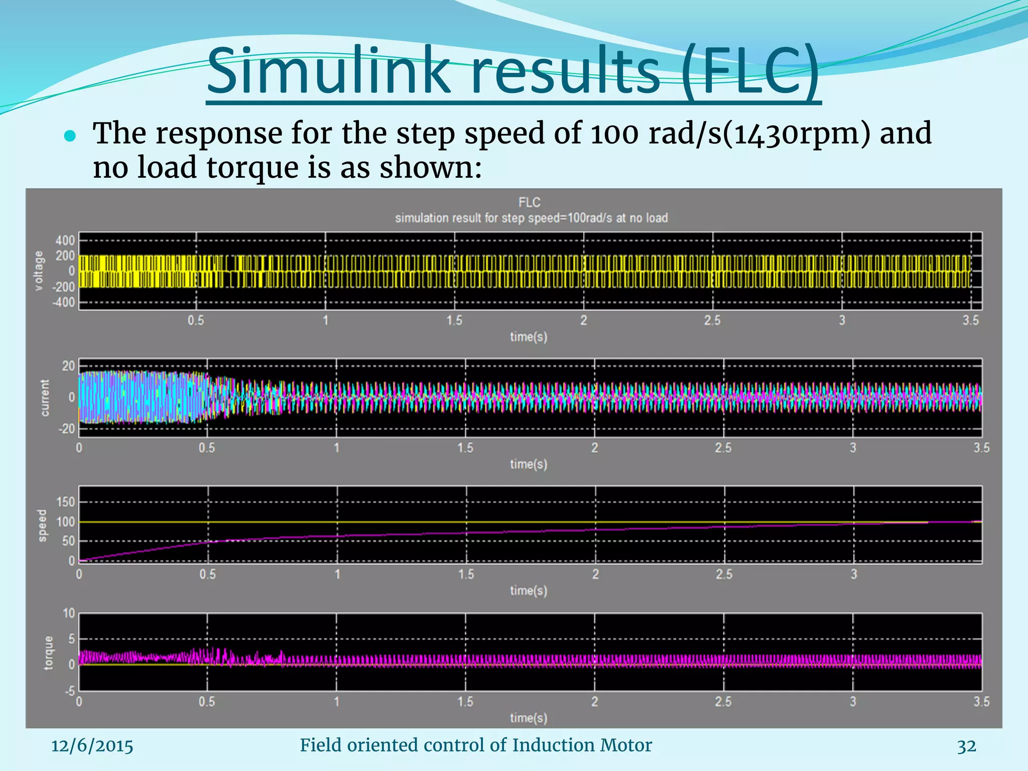
This document discusses the field oriented control (FOC) of induction motors, which offers improved dynamic performance compared to scalar control by decoupling torque and flux control. The FOC method enhances accuracy in controlling AC drives, making it suitable for applications requiring precise behavior. It elaborates on the mathematical models, transformation techniques used in vector control, advantages and limitations, as well as simulation results demonstrating its effectiveness.


![Induction motor
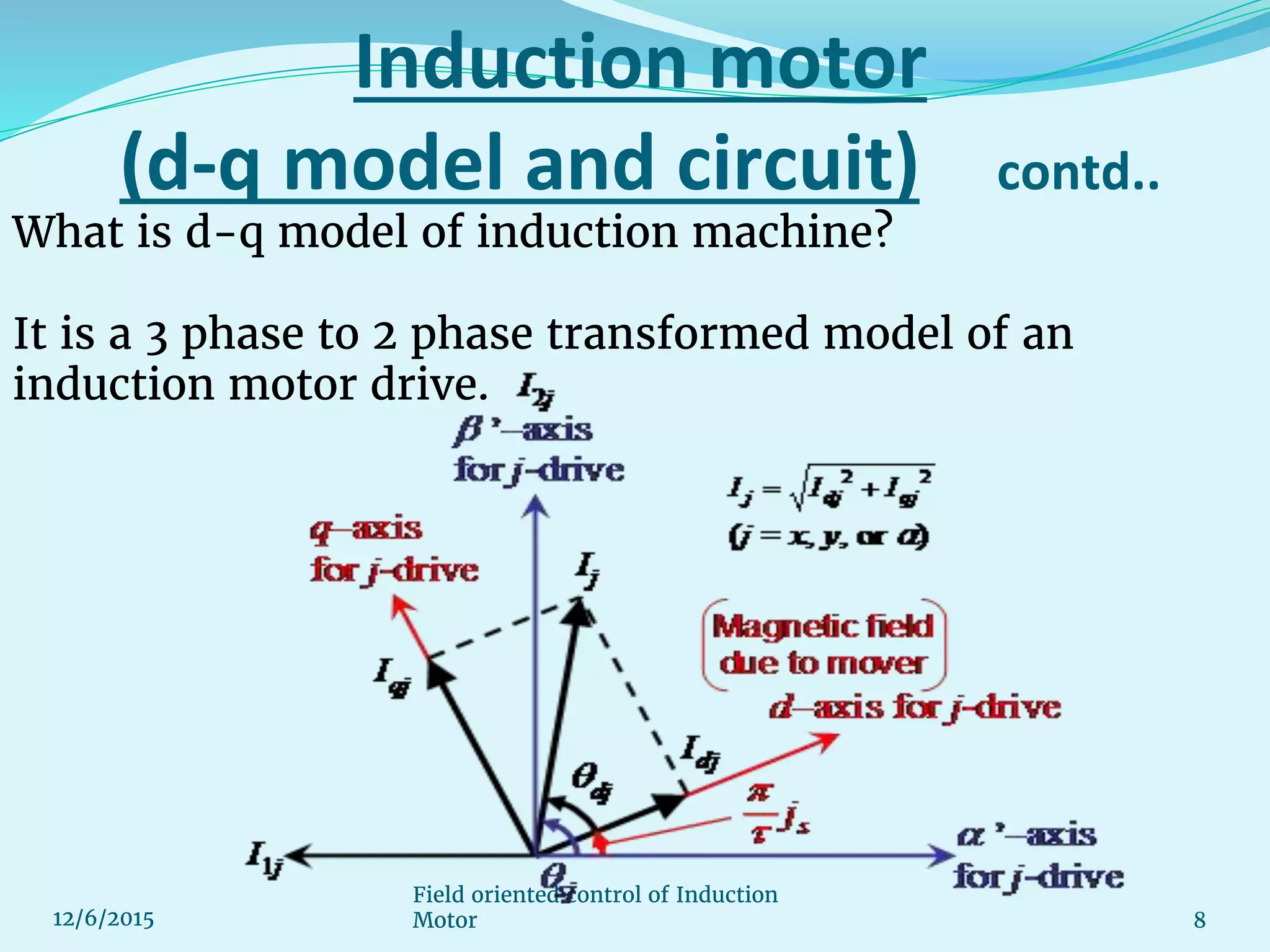
(d-q model and circuit) contd..
9Field oriented control of Induction Motor12/6/2015
This model is obtained by a series of transformations as follows:
1) Clark’s transformation : [3-2 phase stationary ds-qs model.]
2) Park’s transformation : [2 phase stationary to 2 phase synchronously
rotating reference frame.]](https://image.slidesharecdn.com/updatedfieldorientedcontrolofinductionmotor-160303123117/75/Updated-field-oriented-control-of-induction-motor-pptx-9-2048.jpg)