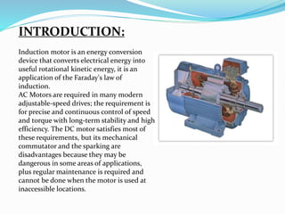
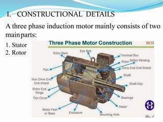
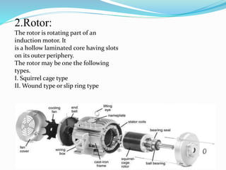
Induction motor is an energy conversion device that converts electrical energy into useful rotational kinetic energy, it is an application of the Faraday's law of induction.AC Motors are required in many modern adjustable-speed drives; the requirement is for precise and continuous control of speed and torque with long-term stability and high efficiency. The DC motor satisfies most of these requirements, but its mechanical commutator and the sparking are disadvantages because they may be dangerous in some areas of applications, plus regular maintenance is required and cannot be done when the motor is used at inaccessible locations.
Many people read about Direct and Indirect Test. It is nothing but a no load and blocked rotor test. It is easy to know what happens in these test by there names.
An alternator is an electrical generator that converts mechanical energy to electrical energy in the form of alternating current. For reasons of cost and simplicity, most alternators use a rotating magnetic field with a stationary armature.
Construction and working of DC series motor is explained in this presentation. important illustrations will help you to understand the working of dc motor, working is described with the example of 4 pole motor.
This presentation describes the per-phase equivalent circuit of induction motor - Power flow diagram - Ratio of air gap power, rotor copper loss and mechanical power developed.
Mr. C.S.Satheesh, M.E.,
Servomotor
Control motors
Two Phase AC Servo Motor
Three Phase AC Servo Motor
DC Servo Motor
AC Servo Motor
Control Type Synchro.
Torque Transmission Type Synchro
Synchros
An induction is an AC electric motor in which the electric current in the rotor needed to produce torque is obtained by electromagnetic induction from the magnetic field of the stator winding. An induction motor therefore does not require mechanical commutation, separate-excitation or self-excitation for all or part of the energy transferred from stator to rotor, as in universal, DC and large synchronous motors. An induction motor's rotor can be either wound type or squirrel-cage type.
A power quality presentation includes definitions of power quality, most common power quality problems and the solutions, standard carves, and practical example of an active filter. Presented by - Eng. Shemy Elhady
Induction motor modelling and applicationsUmesh Dadde
A three-phase induction motor is one of the most popular and versatile motor in electrical
power system and industries. It can perform the best when operated using a balanced three-phase
supply of the correct frequency. In spite of their robustness they do occasionally fail and their
resulting unplanned downtime can prove very costly. Therefore, condition monitoring of
electrical machines has received considerable attention in recent years.
The characteristics of a single phase induction motor are identical to three phase induction motor except that single phase induction motor has no inherent starting torque and some special arrangement have to be made for making itself starting.
Though single phase induction motor is not self-starting, we are using it because the three phase supply is not present at everywhere.
The voltage variation as well as power control of inductive load is essential in industrial sector.
The load may any motor or any inductive load.
We can use thyristor to this job but it is easier using TRIAC.
Industrial Training at Shahjalal Fertilizer Company Limited (SFCL)MdTanvirMahtab2
This presentation is about the working procedure of Shahjalal Fertilizer Company Limited (SFCL). A Govt. owned Company of Bangladesh Chemical Industries Corporation under Ministry of Industries.
Cosmetic shop management system project report.pdfKamal Acharya
Buying new cosmetic products is difficult. It can even be scary for those who have sensitive skin and are prone to skin trouble. The information needed to alleviate this problem is on the back of each product, but it's thought to interpret those ingredient lists unless you have a background in chemistry.
Instead of buying and hoping for the best, we can use data science to help us predict which products may be good fits for us. It includes various function programs to do the above mentioned tasks.
Data file handling has been effectively used in the program.
The automated cosmetic shop management system should deal with the automation of general workflow and administration process of the shop. The main processes of the system focus on customer's request where the system is able to search the most appropriate products and deliver it to the customers. It should help the employees to quickly identify the list of cosmetic product that have reached the minimum quantity and also keep a track of expired date for each cosmetic product. It should help the employees to find the rack number in which the product is placed.It is also Faster and more efficient way.
Welcome to WIPAC Monthly the magazine brought to you by the LinkedIn Group Water Industry Process Automation & Control.
In this month's edition, along with this month's industry news to celebrate the 13 years since the group was created we have articles including
A case study of the used of Advanced Process Control at the Wastewater Treatment works at Lleida in Spain
A look back on an article on smart wastewater networks in order to see how the industry has measured up in the interim around the adoption of Digital Transformation in the Water Industry.
CFD Simulation of By-pass Flow in a HRSG module by R&R Consult.pptxR&R Consult
CFD analysis is incredibly effective at solving mysteries and improving the performance of complex systems!
Here's a great example: At a large natural gas-fired power plant, where they use waste heat to generate steam and energy, they were puzzled that their boiler wasn't producing as much steam as expected.
R&R and Tetra Engineering Group Inc. were asked to solve the issue with reduced steam production.
An inspection had shown that a significant amount of hot flue gas was bypassing the boiler tubes, where the heat was supposed to be transferred.
R&R Consult conducted a CFD analysis, which revealed that 6.3% of the flue gas was bypassing the boiler tubes without transferring heat. The analysis also showed that the flue gas was instead being directed along the sides of the boiler and between the modules that were supposed to capture the heat. This was the cause of the reduced performance.
Based on our results, Tetra Engineering installed covering plates to reduce the bypass flow. This improved the boiler's performance and increased electricity production.
It is always satisfying when we can help solve complex challenges like this. Do your systems also need a check-up or optimization? Give us a call!
Work done in cooperation with James Malloy and David Moelling from Tetra Engineering.
More examples of our work https://www.r-r-consult.dk/en/cases-en/
Immunizing Image Classifiers Against Localized Adversary Attacksgerogepatton
This paper addresses the vulnerability of deep learning models, particularly convolutional neural networks
(CNN)s, to adversarial attacks and presents a proactive training technique designed to counter them. We
introduce a novel volumization algorithm, which transforms 2D images into 3D volumetric representations.
When combined with 3D convolution and deep curriculum learning optimization (CLO), itsignificantly improves
the immunity of models against localized universal attacks by up to 40%. We evaluate our proposed approach
using contemporary CNN architectures and the modified Canadian Institute for Advanced Research (CIFAR-10
and CIFAR-100) and ImageNet Large Scale Visual Recognition Challenge (ILSVRC12) datasets, showcasing
accuracy improvements over previous techniques. The results indicate that the combination of the volumetric
input and curriculum learning holds significant promise for mitigating adversarial attacks without necessitating
adversary training.
Hierarchical Digital Twin of a Naval Power SystemKerry Sado
A hierarchical digital twin of a Naval DC power system has been developed and experimentally verified. Similar to other state-of-the-art digital twins, this technology creates a digital replica of the physical system executed in real-time or faster, which can modify hardware controls. However, its advantage stems from distributing computational efforts by utilizing a hierarchical structure composed of lower-level digital twin blocks and a higher-level system digital twin. Each digital twin block is associated with a physical subsystem of the hardware and communicates with a singular system digital twin, which creates a system-level response. By extracting information from each level of the hierarchy, power system controls of the hardware were reconfigured autonomously. This hierarchical digital twin development offers several advantages over other digital twins, particularly in the field of naval power systems. The hierarchical structure allows for greater computational efficiency and scalability while the ability to autonomously reconfigure hardware controls offers increased flexibility and responsiveness. The hierarchical decomposition and models utilized were well aligned with the physical twin, as indicated by the maximum deviations between the developed digital twin hierarchy and the hardware.
Planning Of Procurement o different goods and services
Modeling and Testing of Induction Motors
1.
2. I. INTRODUCTION
II. CONSTRUCTIONAL DETAILS
III. PRINCIPLE OF OPERATION
IV. TORQUE SLIP CHARACTERISTICS
V. TESTS ON THE INDUCTION MOTOR
VI. SPEED CONTROL OF INDUCTION MOTOR
VII. CONCLUSION
VIII.REFFERENCE
3. INTRODUCTION:
Induction motor is an energy conversion
device that converts electrical energy into
useful rotational kinetic energy, it is an
application of the Faraday's law of
induction.
AC Motors are required in many modern
adjustable-speed drives; the requirement is
for precise and continuous control of speed
and torque with long-term stability and high
efficiency. The DC motor satisfies most of
these requirements, but its mechanical
commutator and the sparking are
disadvantages because they may be
dangerous in some areas of applications,
plus regular maintenance is required and
cannot be done when the motor is used at
inaccessible locations.
4. A three phase induction motor mainly consists of two
mainparts:
1. Stator
2. Rotor
I. CONSTRUCTIONAL DETAILS
5. 1.Stator
The stator consists of a steel
frame which encloses
a hollow cylindrical core made
up of thin laminations of
silicon steel to reduce hysteresis
and eddy current losses. A
number of evenly spaced slots
are provided on the inner
periphery. The insulated
conductors are placed in the
stator slots and are connected to
form a balanced three phase
star or delta connection circuit.
6. 2.Rotor:
The rotor is rotating part of an
induction motor. It
is a hollow laminated core having slots
on its outer periphery.
The rotor may be one the following
types.
I. Squirrel cage type
II. Wound type or slip ring type
7. Squirrel cage type:
It consists of laminated
cylindrical core
having parallel slots
on its outer
periphery, in these
slots one copper or
aluminium bar is
placed. All these bars
are connected at each
end by metal rings,
called end rings.
These bars,
therefore, are
permanently short
circuited and
therefore no external resistance can be
connected.
8. Wound type or slip ring
type:
These consist of laminated
cylindrical core and carries a three
phase winding as in the stator. The
open ends of the rotor winding is
brought out and connected to three
insulated slip rings mounted on the
rotor shaft with one brush resting on
each slip ring. The three brushes are
connected to a three phase star
connected rheostat. These
resistances are included at starting
to limit high circulating current in
the short circuited rotor winding and
to give a large starting torque. These
resistances are
gradually reduced to zero as the
rotor attains its normal speed.
9. II. PRINCIPLE OF
OPERATION
• A Rotating magnetic field (RMF) is set
up in the stator when a 3 phase supply is
given.
• The stationary rotor cuts the revolving
field and due to electromagnetic
induction an emf is induced in the rotor
conductors.
• As the rotor conductors are short
circuited , current starts flowing
through them.
• It becomes a current carrying
conductor in the magnetic field and
starts rotating.
10. Torque-Slip Characteristics:
The curve drawn between the torque and the
slip for a particular value of rotor resistance
is known as torque-slip characteristics.
The motor torque under running condition
is given by, 2
2 22
2 2 2
2 2
K E sR
T
R s X
11. The following points may be noted by the torque-slip characteristics:
1.at s=0, T=0 so that torque-slip curve starts from the origin
2.at normal speed, slip is small so that is negligible as compared to
,
2sX 2R
2
s
T
R
Hence torque slip curve is a straight line from zero slip to a slip that corresponds
to full load.
3.as the slip increases beyond the full load slip, the torque increases and becomes
maximum
at . This maximum torque is known as pull out torque or breakdown
torque. It's value is almost twice that of full load torque when the motor is
operated at its rated voltage and frequency.
2
2
R
s
X
12. 4.when the slip increases beyond the maximum torque, the term
Increases
very rapidly so that may be neglected as compared to .
2
2R
2 2
2
s
T
s X
1
s
as is constant
2X
Thus the torque is now inversely proportional to slip. Hence the torque
slip characteristics is a rectangular parabola.
2 2
2s X
2 2
2s X
13. TESTS ON THE INDUCTION MOTOR
No Load Test:
No load test is performed to determine the no load current, no load power
factor, windage and friction losses, no load resistance and reactance. Since
there is no power output on no load, the power supplied to the stator
furnishes its core loss and the friction and windage losses in the rotor. The
circuit
diagram for the no load test is shown in Fig. 3.
Fig. 3.
14. Blocked Rotor test:
The blocked rotor test is also known as locked rotor test or
short circuit test. This test is employed to find the short circuit
current of the rotor circuit. This test is performed at the rated
current of the induction motor. The circuit diagram for
blocked rotor test is shown in Fig. 4.
15. VII. SPEED CONTROL OF INDUCTION MOTOR
Methods of speed control of induction motor:
A. Pole changing method: B. Stator frequency control: C. Line voltage control:
An induction motor essentially runs at constant speed as the
load is varied. Some industrial drives, however, require
several different speeds or even continually variable speeds
(1 )Nr Ns s
120
(1 )
f
Nr s
P
The operating speed of a 3-phasee induction motor is
given by,
or,
16. Conclusion:
An Induction motor is a constant speed motor
An induction motor is robust in construction, need less maintenance and can
operate in hazardous locations .
Induction motor have two major parts:
•Stator
•Rotor
Test performed on induction motor
•No load test
•Blocked rotor test
Speed of Induction motor can be controlled by
a. Pole changing method
b. Frequency control
c. Line voltage control
17. References:
•Generalized Theory of Electrical Machines By Dr. P.s. Bhimbhra fifth edition 2013
•Principal of Electrical Machines By V.K. Mehta & Rohit Mehta
•Electrical Technology By B.J. Theraja & A.k. Theraja Volume 2