Output equation of Induction motor; Main dimensions; Separation of D and L; Choice of Average flux density; length of air gap; Design of Stator core; Rules for selecting rotor slots of squirrel cage machines; Design of rotor bars and slots; Design of end rings; Design of wound rotor; Magnetic leakage calculations; Leakage reactance of polyphase machines; Magnetizing current; Short circuit current; Operating characteristics; Losses and Efficiency.
These slides provide an elementary description of Power Electronics and its application domains. It also shows the different power devices and converters.
Design factors; Limitations; Modern trends; Electrical
Engineering Materials; Space factor; Choice of Specific
Electric and Magnetic loadings; Thermal Considerations;
Heat flow; Temperature rise; Insulating Materials; Properties;
Rating of Machines; Various Standard Specifications ;
Current Transformer and Potential TransformerRidwanul Hoque
One of the major difference between them is that the current transformer converts the high value of current into low value whereas the potential or voltage transformer converts the high value of voltages into low voltage.
This presentation describes the per-phase equivalent circuit of induction motor - Power flow diagram - Ratio of air gap power, rotor copper loss and mechanical power developed.
he main purpose of transient stability studies is to determineThe main purpose of transient stability studies is to determine
whether a system will remain in synchronism following major
disturbances such as transmission system faults, sudden load
changes, loss of generating units, or line switching.
An alternator is an electrical generator that converts mechanical energy to electrical energy in the form of alternating current. For reasons of cost and simplicity, most alternators use a rotating magnetic field with a stationary armature.
Code of Practice for Power Installations, materials required for power circuit wiring and
their specifications, Prepare the layout diagram of machines showing clearances as per IS
standards, draw wiring plan of the Power circuit for workshops, Decide the type of wiring system, load calculations, determine the size of conductors, main switch, Isolators, sub
switches and protective devices, Draw the SLD of Power Distribution Scheme showing
grading/discrimination of ratings of protective devices, Prepare the schedule of materials with
specifications for workshops and their estimates, Determine the rating of motor for IP set and
the concept (only)of pump house wiring.
Determination of a Three - Phase Induction Machine ParametersAli Altahir
Determining circuit model parameters of a three-phase I.M
1- DC Test: Determine stator resistance, R1
2- No-Load Test: Determine magnetizing reactance, XM
3- Locked-Rotor Test:
_ Determine X1 and X2 ( stator and rotor reactance)
Determine R2 (rotor resistance ) when combined with data from the DC Test
4- Load Test ( Torque – speed characteristics)
Similar to UNIT IV design of Electrical Apparatus (20)
NO1 Uk best vashikaran specialist in delhi vashikaran baba near me online vas...Amil Baba Dawood bangali
Contact with Dawood Bhai Just call on +92322-6382012 and we'll help you. We'll solve all your problems within 12 to 24 hours and with 101% guarantee and with astrology systematic. If you want to take any personal or professional advice then also you can call us on +92322-6382012 , ONLINE LOVE PROBLEM & Other all types of Daily Life Problem's.Then CALL or WHATSAPP us on +92322-6382012 and Get all these problems solutions here by Amil Baba DAWOOD BANGALI
#vashikaranspecialist #astrologer #palmistry #amliyaat #taweez #manpasandshadi #horoscope #spiritual #lovelife #lovespell #marriagespell#aamilbabainpakistan #amilbabainkarachi #powerfullblackmagicspell #kalajadumantarspecialist #realamilbaba #AmilbabainPakistan #astrologerincanada #astrologerindubai #lovespellsmaster #kalajaduspecialist #lovespellsthatwork #aamilbabainlahore#blackmagicformarriage #aamilbaba #kalajadu #kalailam #taweez #wazifaexpert #jadumantar #vashikaranspecialist #astrologer #palmistry #amliyaat #taweez #manpasandshadi #horoscope #spiritual #lovelife #lovespell #marriagespell#aamilbabainpakistan #amilbabainkarachi #powerfullblackmagicspell #kalajadumantarspecialist #realamilbaba #AmilbabainPakistan #astrologerincanada #astrologerindubai #lovespellsmaster #kalajaduspecialist #lovespellsthatwork #aamilbabainlahore #blackmagicforlove #blackmagicformarriage #aamilbaba #kalajadu #kalailam #taweez #wazifaexpert #jadumantar #vashikaranspecialist #astrologer #palmistry #amliyaat #taweez #manpasandshadi #horoscope #spiritual #lovelife #lovespell #marriagespell#aamilbabainpakistan #amilbabainkarachi #powerfullblackmagicspell #kalajadumantarspecialist #realamilbaba #AmilbabainPakistan #astrologerincanada #astrologerindubai #lovespellsmaster #kalajaduspecialist #lovespellsthatwork #aamilbabainlahore #Amilbabainuk #amilbabainspain #amilbabaindubai #Amilbabainnorway #amilbabainkrachi #amilbabainlahore #amilbabaingujranwalan #amilbabainislamabad
Sachpazis:Terzaghi Bearing Capacity Estimation in simple terms with Calculati...Dr.Costas Sachpazis
Terzaghi's soil bearing capacity theory, developed by Karl Terzaghi, is a fundamental principle in geotechnical engineering used to determine the bearing capacity of shallow foundations. This theory provides a method to calculate the ultimate bearing capacity of soil, which is the maximum load per unit area that the soil can support without undergoing shear failure. The Calculation HTML Code included.
Vaccine management system project report documentation..pdfKamal Acharya
The Division of Vaccine and Immunization is facing increasing difficulty monitoring vaccines and other commodities distribution once they have been distributed from the national stores. With the introduction of new vaccines, more challenges have been anticipated with this additions posing serious threat to the already over strained vaccine supply chain system in Kenya.
TECHNICAL TRAINING MANUAL GENERAL FAMILIARIZATION COURSEDuvanRamosGarzon1
AIRCRAFT GENERAL
The Single Aisle is the most advanced family aircraft in service today, with fly-by-wire flight controls.
The A318, A319, A320 and A321 are twin-engine subsonic medium range aircraft.
The family offers a choice of engines
Quality defects in TMT Bars, Possible causes and Potential Solutions.PrashantGoswami42
Maintaining high-quality standards in the production of TMT bars is crucial for ensuring structural integrity in construction. Addressing common defects through careful monitoring, standardized processes, and advanced technology can significantly improve the quality of TMT bars. Continuous training and adherence to quality control measures will also play a pivotal role in minimizing these defects.
CFD Simulation of By-pass Flow in a HRSG module by R&R Consult.pptxR&R Consult
CFD analysis is incredibly effective at solving mysteries and improving the performance of complex systems!
Here's a great example: At a large natural gas-fired power plant, where they use waste heat to generate steam and energy, they were puzzled that their boiler wasn't producing as much steam as expected.
R&R and Tetra Engineering Group Inc. were asked to solve the issue with reduced steam production.
An inspection had shown that a significant amount of hot flue gas was bypassing the boiler tubes, where the heat was supposed to be transferred.
R&R Consult conducted a CFD analysis, which revealed that 6.3% of the flue gas was bypassing the boiler tubes without transferring heat. The analysis also showed that the flue gas was instead being directed along the sides of the boiler and between the modules that were supposed to capture the heat. This was the cause of the reduced performance.
Based on our results, Tetra Engineering installed covering plates to reduce the bypass flow. This improved the boiler's performance and increased electricity production.
It is always satisfying when we can help solve complex challenges like this. Do your systems also need a check-up or optimization? Give us a call!
Work done in cooperation with James Malloy and David Moelling from Tetra Engineering.
More examples of our work https://www.r-r-consult.dk/en/cases-en/
Overview of the fundamental roles in Hydropower generation and the components involved in wider Electrical Engineering.
This paper presents the design and construction of hydroelectric dams from the hydrologist’s survey of the valley before construction, all aspects and involved disciplines, fluid dynamics, structural engineering, generation and mains frequency regulation to the very transmission of power through the network in the United Kingdom.
Author: Robbie Edward Sayers
Collaborators and co editors: Charlie Sims and Connor Healey.
(C) 2024 Robbie E. Sayers
Industrial Training at Shahjalal Fertilizer Company Limited (SFCL)MdTanvirMahtab2
This presentation is about the working procedure of Shahjalal Fertilizer Company Limited (SFCL). A Govt. owned Company of Bangladesh Chemical Industries Corporation under Ministry of Industries.
Event Management System Vb Net Project Report.pdfKamal Acharya
In present era, the scopes of information technology growing with a very fast .We do not see any are untouched from this industry. The scope of information technology has become wider includes: Business and industry. Household Business, Communication, Education, Entertainment, Science, Medicine, Engineering, Distance Learning, Weather Forecasting. Carrier Searching and so on.
My project named “Event Management System” is software that store and maintained all events coordinated in college. It also helpful to print related reports. My project will help to record the events coordinated by faculties with their Name, Event subject, date & details in an efficient & effective ways.
In my system we have to make a system by which a user can record all events coordinated by a particular faculty. In our proposed system some more featured are added which differs it from the existing system such as security.
Hybrid optimization of pumped hydro system and solar- Engr. Abdul-Azeez.pdffxintegritypublishin
Advancements in technology unveil a myriad of electrical and electronic breakthroughs geared towards efficiently harnessing limited resources to meet human energy demands. The optimization of hybrid solar PV panels and pumped hydro energy supply systems plays a pivotal role in utilizing natural resources effectively. This initiative not only benefits humanity but also fosters environmental sustainability. The study investigated the design optimization of these hybrid systems, focusing on understanding solar radiation patterns, identifying geographical influences on solar radiation, formulating a mathematical model for system optimization, and determining the optimal configuration of PV panels and pumped hydro storage. Through a comparative analysis approach and eight weeks of data collection, the study addressed key research questions related to solar radiation patterns and optimal system design. The findings highlighted regions with heightened solar radiation levels, showcasing substantial potential for power generation and emphasizing the system's efficiency. Optimizing system design significantly boosted power generation, promoted renewable energy utilization, and enhanced energy storage capacity. The study underscored the benefits of optimizing hybrid solar PV panels and pumped hydro energy supply systems for sustainable energy usage. Optimizing the design of solar PV panels and pumped hydro energy supply systems as examined across diverse climatic conditions in a developing country, not only enhances power generation but also improves the integration of renewable energy sources and boosts energy storage capacities, particularly beneficial for less economically prosperous regions. Additionally, the study provides valuable insights for advancing energy research in economically viable areas. Recommendations included conducting site-specific assessments, utilizing advanced modeling tools, implementing regular maintenance protocols, and enhancing communication among system components.
Water scarcity is the lack of fresh water resources to meet the standard water demand. There are two type of water scarcity. One is physical. The other is economic water scarcity.
Saudi Arabia stands as a titan in the global energy landscape, renowned for its abundant oil and gas resources. It's the largest exporter of petroleum and holds some of the world's most significant reserves. Let's delve into the top 10 oil and gas projects shaping Saudi Arabia's energy future in 2024.
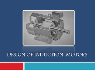
2. Introduction
Induction motors are the prime movers in most of the
Industries (Work Horse of Motion Industries)
simple design, rugged, low-price, easy maintenance
wide range of power ratings: fractional horsepower to
10 MW
run essentially as constant speed from no-load to full
load
Its speed depends on the frequency of the power
source
applications such as centrifugal pumps, conveyers,
compressors crushers, and drilling machines etc
2
3. Construction Details
AC induction motor comprises two electromagnetic
parts
Stationary part called the stator
Rotating part called the rotor
Differs from a dc machine in the following aspects.
Laminated stator
Absence of commutator & Uniform and small air gap
Practically almost constant speed
The stator and the rotor are each made up of
An electric circuit - usually made of insulated
copper or aluminum winding, to carry current
A magnetic circuit - usually made from laminated
3
4. Stator - Construction
The stator is the outer stationary part
of the motor
outer cylindrical frame - yoke which is
made either of welded sheet steel,
cast iron or cast aluminum alloy
The magnetic path - comprises a set
of slotted steel laminations called
stator core pressed into the cylindrical
space inside the outer frame.
It is laminated to reduce eddy
currents, reducing losses and
heating
Smooth Yoke
Ribbed Yoke
4
5. Stator - Construction
A set of insulated electrical windings, which are placed inside the slots
of the laminated Stator.
For a 3-phase motor, 3 sets of windings are required, one for each phase
connected in either star or delta..
Stator Laminations
cross sectional view of an induction motor
5
6. Rotor - Construction
Rotor is the rotating part of
the induction motor
of a set of slotted silicon
steel laminations pressed
together to form of a
cylindrical magnetic circuit
and the electrical circuit
The electrical circuit of the
rotor is of
Squirrel cage rotor
Wound rotor (Slip Ring
Rotor)
6
7. Squirrel Cage Rotor
set of copper or aluminum bars installed
into the slots, which are connected to an
end-ring at each end of the rotor
windings resembles a ‘squirrel cage
bars ring
ring
bar
s
ring
ring
Even though the
aluminum rotor bars are
in direct contact with the
steel laminations,
practically all the rotor
current flows through the
aluminum bars and not in
the lamination
7
8. Wound Rotor
consists of three sets of insulated windings
with connections brought out to three slip
rings mounted on one end of the shaft
The external connections to the rotor are
made through brushes onto the slip rings
Brushe
Slip rings
8
9. Some more parts
Two end- flanges to support
the two bearings, one at the
driving-end and the other at
the non driving-end.
Two sets of bearings to
support the rotating shaft
Steel shaft for transmitting
the mechanical power to the
load
Cooling fan located at the
non driving end
Terminal box on top of the
yoke or on side to receive the
9
11. Main purpose of designing
is to obtain the complete physical dimensions of all the
parts
to satisfy the customer Needs
Physical Dimensions
The main dimensions of the stator.
Details of stator windings.
Design details of rotor and its windings
Performance characteristics (iron and copper losses, no
load current, power factor, temperature rise and
efficiency)
Customer Needs
out put power, voltage, number of phases, speed,
frequency, connection of stator winding, type of rotor
11
12. Output Equation
mathematical expression which gives the relation between
the various physical and electrical parameters of the
electrical machine
12
13. Output Equation
Vph = phase voltage
Iph = phase current
Iz = Current in each
Conductor
Z = Total no of conductors
Tph = no of turns/phase
Ns = Synchronous speed in
rpm
ns = synchronous speed in
rps
p = no of poles,
ac = Specific electric
loading
Ø= air gap flux/pole
Bav = Average flux density
kw = winding factor
eff = efficiency
cos Ø = power factor
D = Diameter of the stator,
L = Gross core length
Co = Output coefficient
13
14. Output Equation
For a 3 Ø machine,
kVA rating Q = 3 Vph Iph 10-3 kW
Assuming, Vph = Eph
Eph = 4.44 f Ø Tph kW
f = PNS/120 = P ns/2
Output = 3 x 4.44 x Pns/2 x Ø Tph Kw Iph x 10-3 kW
Output = 6.66 x PØ x Iph Tph x ns x Kw x 10-3 kW
Iz = Iph / a
Let Iz = Iph (1 Parallel Path)
Z = 3 x 2 Tph ( Tph = Z/6)
14
15. Output Equation
Total Magnetic Loading PØ = Bav π DL
Total Electric Loading ac = Iz Z/ π. D
Output = 1.11 x PØ x Iz Z x ns x Kw x 10-3 kW
Output = 1.11 x Bav π. DL x ac x π. D x ns x Kw x 10-3 kW
Output = 11 Bav ac Kw 10-3 x D2L ns kW
Output (Q) = Co D2L ns kW
Where, Co = 11 Bav ac Kw 10-3
kVA input Q = H.P x 0.746 (kW) / eff cos Ø
15
16. Choice of Specific loadings
Specific Magnetic loading or Air gap flux density (Bav)
Iron losses largely depend upon air gap flux density
Limitations :
Magnetising current high – Poor power factor
Flux density in teeth < 1.8 Tesla
Flux density in core 1.3 – 1.5 Tesla
Advantages of Higher value of Bav
Large Flux/Pole – Tph less – Leakage reactance less - Overload
capacity increases
Size of the machine reduced
Cost of the machine decreases
For 50 Hz machine, The suitable values of Bav is 0.35 – 0.6 Tesla.
16
17. Choice of Specific loadings
Specific Electric Loading (ac)
Advantages of Higher value
Reduced size
Reduced cost
Disadvantages of Higher value
Higher amount of copper
More copper losses
Increased temperature rise
Lower overload capacity
Normal range 10000 ac/m – 450000 ac/m.
For Machines high voltage rating – ac value Small
17
18. Choice of power factor and
efficiency
power factor and efficiency under full load conditions will
increase with increase in rating of the machine
Percentage magnetizing current and losses will be
lower for a larger machine than that of a smaller
machine
the power factor and efficiency will be higher for a high
speed machine than the same rated low speed machine
because of better cooling conditions
Squirrel cage – Efficiency – 0.72 to 0.91 & P.F – 0.66 to
0.9
Slip ring - Efficiency – 0.84 to 0.91 & P.F – 0.7 to 0.92
18
19. Separation of D and L
The output equation gives the relation between D2L product
and output of the machine
The separation of D and L for this product depends on a
suitable ratio between gross length and pole pitch ( L / τ)
to obtain the best power factor the following relation will be
usually assumed for separation of D and L.
Pole pitch/ Core length = 0.18/pole pitch
DesignEconomicalOverall
higherfor
PFGoodfor
DesignOverallGood
L
:0.25.1
:5.1
:25.11
:1
D = 0.135 P Sqrt
(L)
19
20. Peripheral Speed
D and L have to satisfy the condition imposed on the value
of peripheral speed
For the normal design of induction motors the calculated
diameter of the motor should be such that the peripheral
speed must be below 30 m/s.
In case of specially designed rotor the peripheral speed can
be 60 m/s.
Ventilating Ducts : Provided when core length exceeds
100 – 125 mm. The width of Duct – 8 to 10 mm
20
21. Design of Stator
The Design consideration of Stator Involves in estimation of
Stator Winding
Stator Turns per Phase
Length of Mean Turn
Stator Conductors
Shape & No of Stator Slots
Area of Stator Slot
Stator Teeth
Depth of Stator Core
21
22. Stator Winding
For Small Motors up to 5 HP Single layer Winding like
Mush Winding
Whole coil Concentric Winding
Bifurcated concentric winding is used.
Generally Double layer Winding ( Lap or Wave ) with
diamond shaped coils is used.
The three phases of winding can be connected in either star
or Delta depending on the Starting Methods Employed.
Squirrel cage – Star Delta Starter – Stators designed - Delta
Slip ring – Rotor resistance – Either star or Delta
22
26. Stator Turns per phase
Stator Phase Voltage Es = 4.44 f Ø Ts Kws
Stator Turns per phase Ts = Es / 4.44 f Ø Kws
Where, Kws = 0.955 Winding factor
Specific Magnetic Loading, Bav = Flux per pole / Area under a
pole
= p Ø / pi . D L
Ø = Bav x pi . D L / p
26
27. Length of Mean Turn of winding
For Stators that use up to 650 V
Length of Mean turn , Lmts = 2L + 2.3 τ + 0.24
Where, L – Length of Stator Core
τ - Pole Pitch
Resistance of the stator winding per phase is calculated
using the formula = (0.021 x lmt x Tph ) / as where lmt is in
meter and as is in mm2
27
28. Stator Conductors
kVA rating Q = 3 Es Is 10-3 kW
Stator Current / Phase , Is = Q / 3 Es x 10-3
Area of Cross Section , as = Is / gs
Where, gs – Current Density – 3 to 5 A/mm2
Area of Cross Section , as = pi ds
2 / 4
Where, ds – Diameter of Stator Conductor
Round conductors are generally used
For diameter more than 2 or 3 mm – Bar or Strip
conductors are used
28
29. Stator Slots
In general two types of stator
slots - open slots and
semiclosed slots
Open Slots :
slot opening will be equal to
that of the width of the slots.
assembly and repair of winding
are easy.
slots will lead to higher air gap
contraction factor and hence
poor power factor
open slots
29
30. Stator Slots
Semi enclosed Slots :
slot opening is much smaller
than the width of the slot.
assembly of windings is more
difficult and takes more time
compared to open slots
costlier
Air gap characteristics are
better compared to open type
slots
30
31. Choice of Stator Slots
number of slots/pole/phase may be selected as three or
more for integral slot winding
fractional slot windings number of slots/pole/phase may be
selected as 3.5
Slot Pitch for open type of Slots should be 15 to 25 mm.
Slot Pitch for Semi enclosed type of Slots should be < 15
mm.
Stator slot pitch, Yss = Gap Surface / Total No of Slots
= π . D / Ss
So, Ss = π . D / Yss
Stator Slots Ss = Number of phases x poles x slots/pole/phase
31
32. Conductors per Slot
Total No of Stator Conductors Zs = Phase x
Conductors/Phase
= 3 x 2 Ts = 6 Ts
Conductors per Slot, Zss = Total No of Zs / Total No of Ss
= 6 Ts / Ss
Where, Ts – Stator Turns per Phase
Ss – Total Stator Slots
Zss – Must be Even for double layer
winding
32
33. Area of Stator Slot
Area of each slot = Copper Area per slot / Space Factor
= Zss x as / Space factor
Where, Zss – No of Conductors per slot
as – Area of each Conductor
Space Factor – 0.25 to 0.4
33
34. Stator Teeth
The Dimensions of slot determine the flux density in the
teeth.
Higher Flux Density – iron loss – Greater Magnetising mmf.
Mean Flux density in tooth < 1.7 Wb/m2
Minimum teeth Area per pole = Øm / 1.7
Teeth area per pole = Ss / p x Li x Wts (Width of stator
Tooth)
So, Øm / 1.7 = (Ss / p) x Li x Wts min
Wts min = Øm / 1.7 (Ss / p ) x Li
34
35. Depth of Stator Core
flux density in Stator Core < 1.5
Wb/m2.
So,Flux in core = half of flux /
pole
= Øm / 2
Area = Flux / Flux Density
= (Øm / 2 ) / Bcs
Also, Area = Li x depth (dcs)
(Øm / 2 ) / Bcs = Li x dcs
Depth of the core, dcs = Øm / 2
Bcs Li
Outer Diameter,Do = D + 2(dss +
Do
dcs
dss
D
35
40. Length of Air Gap
Advantages larger air gap length :
Increased overload capacity
Increased cooling
Reduced unbalanced magnetic pull
Reduced in tooth pulsation
Reduced noise
Disadvantages of larger air gap length
Increased Magnetising current
Reduced power factor
For Small Induction Motor – lg = 0.2 + 2 Sqrt(DL) mm
Lg = 0.125 +0.35D+ L + 0.015 Va mm
For General Use - lg =0.2 + D mm
For journal bearings - lg = 1.6 sqrt (D) – 0.25 mm
40
44. Design of Rotor
squirrel cage type are rugged and simple in construction
and comparatively cheaper & has lower starting torque.
In this type, the rotor consists of bars of copper or
aluminum accommodated in rotor slots.
Slip ring induction motors are complex in construction and
costlier with the advantage that they have the better
starting torque.
This type of rotor consists of star connected distributed
three phase windings.
44
45. Design of Rotor
Cogging and Crawling are the two phenomena which are
observed due to wrong combination of number of rotor and
stator slots.
In addition, induction motor may develop unpredictable
hooks and cusps in torque speed characteristics or the
motor may run with lot of noise
45
46. Crawling
The rotating magnetic field
produced in the air gap of the will
be usually non sinusoidal and
generally contains odd harmonics
of the order 3rd, 5th and 7th
The third harmonic flux will
produce the three times the
magnetic poles compared to that of
the fundamental. Similarly the 5th
and 7th harmonics
The motor with presence of 7th
harmonics is to have a tendency to
run the motor at one seventh of its
normal speed
46
47. Cogging
When the number of rotor slots
are not proper in relation to
number of stator slots the
machine refuses to run and
remains stationary.
Under such conditions there will
be a locking tendency between
the rotor and stator – Cogging
rotor slots will be skewed by
one slot pitch to minimize the
tendency of cogging, torque
defects like synchronous hooks
and cusps and noisy operation
while running.
47
48. Squirrel Vz Wound
No Slip rings
Higher Efficiency
Star – Delta starter sufficient
Cheaper
Small copper loss
Better P.F, greater Overload
Capacity
48
Possible to insert resistance
in rotor – Increases starting
Torque
Low starting current
Rotor Resistance starter
49. Design of Squirrel Cage Rotor
The Design involves
Diameter of the Rotor
Choice and Design of Rotor bars & slots
Design of End Rings
Diameter of Rotor
Should be Slightly less than that of Stator to avoid Mechanical Friction
Diameter of Rotor, Dr = D – 2 lg
Where, D – Diameter of Stator Bore
lg – length of air gap
49
bar
s
ring
ring
50. Choice of Rotor Slots
To avoid cogging and crawling: (a)Ss Sr (b) Ss - Sr ±3P
To avoid synchronous hooks and cusps in torque speed characteristics
±P, ±2P, ±5P.
To noisy operation Ss - Sr ±1, ±2, (±P ±1), (±P ±2)
Design of Rotor Bars
Rotor bar current, Ib= (6 Is Ts Kws cos Ø) / Sr = 0.85 x (6 Is Ts) / Sr
(approx)
Where , Is – Stator Current per Phase
Ts – Stator Turns per phase
Sr – Number of rotor slots
Kws – Winding factor of stator
50
51. Design of Rotor Bars
Area of each rotor bar, ab = Ib / gb in mm2
Where, Ib – Rotor bar current
gb – Current density of rotor bar , Normally 4 – 7 A/mm2
Copper loss in rotor bars
Length of rotor bar Lb = L + allowance for skewing
Rotor bar resistance, rb = 0.021 x Lb / ab
Copper loss in rotor bars = Ib
2 x rb x number of rotor bars
51
52. Design of End Rings
All the rotor bars are short circuited by
connecting them to the end rings
The rotating magnetic filed produced will
induce an emf in the rotor bars which will be
sinusoidal over one pole pitch.
As the rotor is a short circuited body, there
will be current flow because of this emf
induced.
In one pole pitch, half of the number of bars
and the end ring carry the current in one
direction and the other half in the opposite
direction.
Thus the maximum end ring current may be
taken as the sum of the average current in
half of the number of bars under one pole.
52
54. Design of End Rings
Maximum value of End ring current,
Ie(max) = ½ x ( Number rotor bars / pole) x Ib(av)
= ½ x (Sr/p) x Ib(av)
Where Ib(av) = (2/π) x Ib(max)
Ib(max) = √2 Ib
Since Bar current is Sinusoidal
Ie(max) = √2 Sr Ib / πp
Rms value of ring current = Ie = Ie(max) / √2
54
55. Design of End Rings
Area of end rings
Area of each end ring ae = Ie / ge mm2,
Where ge = Current density in end ring – 4 to 7 A/mm2
Area of each end ring ae = depth x Thickness of end
ring
Area of each end ring ae = de x te
Copper loss in End Rings
Mean diameter of the end ring (Dme) - 4 to 6 cms less of the
rotor
Mean length of the current path in end ring lme = π Dme
resistance of the end ring re = 0.021 x lme / ae
Total copper loss in end rings = 2 x Ie2 x re
55
56. Design of Wound Rotor
Rotor carries distributed star connected 3 phase winding
Three ends of the winding are connected to the slip rings
External resistances can be connected to these slip rings
at starting, which will be inserted in series with the windings
which will help in increasing the torque at starting
The Design involves in
Rotor winding
Number of Rotor slots
Number of rotor turns
Rotor Current
Area of rotor conductor
Dimensions of rotor teeth
Rotor core & Slip rings , brushes
56
57. Design of Wound Rotor
Rotor winding : Small Motors – Mush Type
: Large Motors – Double layer Bar Type
: Motors > 750 kW – Barrel winding
No of Rotor turns
Turns ratio Er/Es = Kwr Tr / Kws Ts
Rotor turns/ phase, Tr = Kws Ts Er / Kwr Es
rotor ampere turn = 0.85 x stator ampere turn
Ir Tr = 0.85 x Is Ts
Rotor current Ir = 0.85 Is Ts / Tr
57
58. Design of Wound Rotor
Area of rotor conductor, ar = Ir / gr
Where gr – current density – 3 to 5 A/mm2
Choice of rotor slots
Rotor slots should not be equal to stator slots
Generally for wound rotor motors a suitable value is
assumed for number of rotor slots per pole per phase,
and then
total number of of rotor slots are calculated.
Semi closed slots are used for rotor slots.
58
59. Design of Wound Rotor
Rotor teeth
flux density in rotor tooth < 1.7 Wb/m2
Minimum teeth area / pole = Flux per pole / Max flux density
= Øm / 1.7
Tooth area / pole = No of rotor slots/pole x Net iron
length x width of the tooth
= (Sr / p) x Li x Wtr
Equating both
(Sr / p) x Li x Wtr = Øm / 1.7
Wtr(min) = Øm / (1.7 x (Sr / p) x Li )
Wtr(min) actual = root Rotor slot pitch – rotor slot width
= π (Dr – 2 dsr) / Sr - Wsr
59
60. Design of Wound Rotor
Rotor Core
The flux density in the rotor core = Stator core density
Depth of rotor core, dcr = Øm / (2 x Bcr x Li )
Where, Bcr – Flux density in rotor core
Inner Diameter of rotor lamination, Di = Dr – 2(dsr + dcr)
Where, dcr – depth of rotor core
dsr – depth of rotor slot
Slip ring & brushes:
Area of Slip ring = rotor current / Current density ( 4 to 7 A/mm2)
Dimension of Brushes - Current density ( 0.1 to 0.2 A/mm2)
60
61. Performance Evaluation
The parameters for performance evaluation are iron losses,
no load current, no load power factor, leakage reactance
etc
Iron losses: Iron loss has two components, hysteresis and
eddy current losses occurring in the iron parts depend
upon the frequency of the applied voltage
The frequency of the induced voltage in rotor is equal to
the slip frequency which is very low and hence the iron
losses occurring in the rotor is negligibly small.
Hence the iron losses occurring in the induction motor is
mainly due to the losses in the stator alone
Total iron losses in induction motor = Iron loss in stator core + iron losses in stator
teeth.
61
68. Short Circuit (Blocked Rotor)
Current
Resistance and Leakage Reactance - Needs to be evaluated
Find the Stator and Rotor Resistance
Find total resistance of motor as viewed from stator
Finally Find Rotor current
If rotor leakage reactance & Loss component of No load current –
Neglected
Stator current equivalent to rotor current = Is cos Ø
Where Is – Stator current
cos Ø - Power Factor
68
70. Circle Diagram
We should know following for drawing the circle diagram
No load current and no load power factor
Short circuit current and short circuit power factor
Draw I0 at an angle from vertical line assuming some scale for current.
Draw Isc at an angle from vertical line.
Join AB, which represents the o/p line of the motor to power scale.
Draw a horizontal line AF, and erect a perpendicular bisector on the o/p
line AB so as to meet the line AF at the point O’. Then O’ as center and
AO’ as radius, draw a semi circle ABF.
Draw vertical line BD; divide line BD in the ratio of rotor copper loss to
stator copper loss at the point E.
Join AE, which represent the torque line
70
71. Circle Diagram
Full load current & power factor
Draw a vertical line BC representing the rated o/p of the
motor s per the power scale. From point C, draw a line
parallel to o/p line, so as to cut the circle at pint P. Join OP
which represents the full load current of the motor to
current scale. Operating power factor can also be found
out.
Full load efficiency
Draw a vertical line from P as shown in above figure.
PL = O/p Power
PX = I/p Power
71
73. Problems
Solution:
kVA input, Q = output / eff x P.F
Co = 11 Bav ac Kw 10-3
Ns = 2f / p rps
Sub the value of Co & ns in o/p equation
Q = Co D2L ns Find D2L
Estimate the stator core dimensions, number of stator slots, no of
stator Conductors per slot for a 100kW, 3300V, 50Hz, 12 pole, Star
connected slip ring induction motor Bav = 0.4 Wb/m2, ac = 25000
amp.cond/m, Eff = 0.9, P.F = 0.9, Choose the main dimensions to give
best power factor. The slot loading should not exceed 500 amp.cond
73
74. Problems
For best power factor
τ = √(0.18L) we get a equation in terms of D & L
Sub and solve for D & L.
Stator star connected Es = El/√3
Flux per pole Ø = Bav π DL / p
Find Ts using Flux Ts = Es / 4.44 f Ø Kws
Slot pitch should be 15 to 25 mm
Find Ss when Yss = 15 & 25 mm Ss = π . D /
Yss
74
75. Problems
We get a range of Ss from the above step
Now Assume q = 2, 3, 4..etc and find Ss
Stator Slots Ss = Number of phases x poles x slots/pole/phase
Select Ss that is within the range
Check for Slot loading = Is .Zss
Since Star connected Il = I ph = Is
Is = kVA x 103 / 3 x VL & Zss = 6 Ts / Ss
Finalise the no of slots Ss
Now find the new Total stator conductors = Ss .Zss
& Turns / Phase, Ts = Zss . Ss / 6
75
76. Problems
76
Estimate the main dimensions, air gap length, number of stator slots,
stator turns / phase & cross sectional area of stator and rotor conductors
for a 3 phase, 15HP, 400V, 50Hz, 6, 975rpm induction motor, The motor
is suitable for star delta starting. Bav = 0.45 Wb/m2, ac = 20000
amp.cond/m, Eff = 0.9, P.F = 0.85, L/τ = 0.85.
Solution:
kVA input, Q = HP X 0.746 / eff x P.F
Co = 11 Bav ac Kw 10-3
Ns = 2f / p rps
Sub the value of Co & ns in o/p equation
Q = Co D2L ns Find D2L
77. Problems
77
Given L/τ = 0.85, Where τ = πd/p we get a equation
in terms of D & L
Substitute and solve for D & L.
Delta connected Es = El = Eph
Flux per pole Ø = Bav π DL / p
Find Ts using Flux Ts = Es / 4.44 f Ø Kws
Slot pitch should be 15 to 25 mm
Find Ss when Yss = 15 & 25 mm Ss = π . D /
Yss
78. Problems
78
We get a range of Ss from the above step
Now Assume q = 2, 3, 4..etc and find Ss
Stator Slots Ss = Number of phases x poles x slots/pole/phase
Select Ss that is within the range
Finalise the no of slots Ss
Find Zss = 6 Ts / Ss
Now find the new Total stator conductors = Ss .Zss
& Turns / Phase, Ts = Zss . Ss / 6
79. Problems
79
Assume gs = 3 A/mm2 find Area Stator conductor as =
Is / gs
Where Is = Iph = Q x 103 / 3 Eph
Length of Airgap, lg = 0.2 + 2 Sqrt(DL) mm
Choose the No of Rotor slots Such that Ss – Sr are
not equal
Find Rotor bar current, Ib = 0.85 x (6 Is Ts) / Sr
Assume gr = 4 A/mm2 find Area of rotor ar = Ir / gr
Find End Ring Current, Ie = Sr Ib / πp
Assume ge = 4 A/mm2 find Area of End rings ae = Ie / ge
80. Problems
80
Design a cage rotor for a 40 HP, 3 Phase , 400 V, 50 Hz, 6 pole, delta
connected induction motor having a full load efficiency 87% and a full
load P.F of 0.85. Take D =33 cm and L = 17 cm. Stator slots = 54,
conductors per slot = 14. Assume suitably the missing data if any.
Given: 3 phase, p=6, Ss =54, Zss = 14, Q=40
HP, Delta connected, V=400 V, Eff. = 0.87,
P.f = 0.85, D=0.33m, L= 17m
Solution:
kVA input, Q = HP X 0.746 / eff x P.F
81. Problems
81
Choose the No of Rotor slots Such that Ss – Sr are not
equal to 0,±p, ,±2p, ,±3p, ,±5p, ±1, ±2, ±(p ±1), ±(p ±2)
0,±6, ,±12, ,±18,±30, ±1, ±2, ±7,±5, ±8, ±4
Ss – Sr = ±3, ±9
Choose the minimum and Sr = 54-3 = 51
Find Rotor bar current, Ib = 0.85 x (6 Is Ts) / Sr
Find Is and Ts
Zss = 6 Ts / Ss, Ts = Zss x Ss /6
find Is from input KVA = 3 Eph x Iph x 10-3
Since delta connected, Eph =V = 400, Iph = Q / 3 Eph x
10-3
82. Problems
82
Find End Ring Current, Ie = Sr Ib / πp
Assume gr = 4 A/mm2 find Area of rotor Bar ar = Ir / gr
Assume ge = 4 A/mm2 find Area of End rings ae = Ie / ge
Find length of rotor core = length of stator core
Find Diameter of rotor = Dr = D – 2lg
Find Length of Airgap, lg = 0.2 + 2 Sqrt(DL) mm