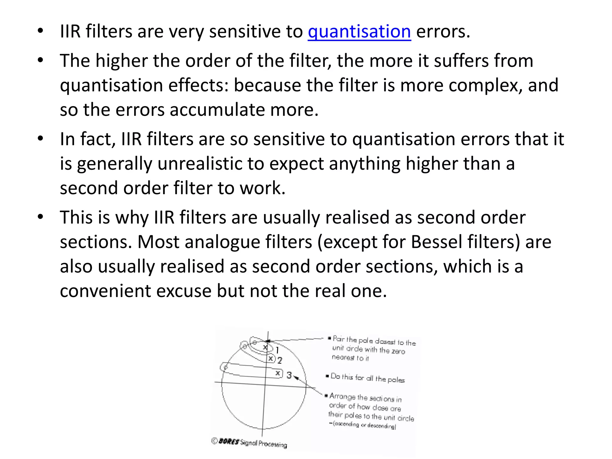
IIR FILTERS
Digital Signal processing
Marmik Kothari
LY EC-
140410111027
SVIT VASAD
Basics of IIRs
Two convolutionsare involved: one with the previous inputs, and
one with the previous outputs. In each case the convolving function
is called the filter coefficients.
• If such a filter is subjected to an impulse (a signal consisting of
one value followed by zeroes) then its output need not
necessarily become zero after the impulse has run through the
summation. So the impulse response of such a filter can be
infinite in duration. Such a filter is called an Infinite Impulse
Response filter or IIR filter
• The impulse response need not necessarily be
infinite: if it were, the filter would be unstable. In
fact for most practical filters, the impulse response
will die away to a negligibly small level.
• One might argue that mathematically the
response can go on for ever, getting smaller and
smaller: but in a digital world once a level gets
below one bit it might as well be zero.
• The Infinite Impulse Response refers to the ability
of the filter to have an infinite impulse response
and does not imply that it necessarily will have
one: it serves as a warning that this type of filter is
prone to feedback and instability.
DIERCT FORM I
• The block diagram is in two halves:
• and since the results from each half are simply added
together it does not matter in which order they are
calculated.
• So the order of the halves can be swapped:
This is called direct form 2.
• Its advantage is that it needs
less delay elements. And since
delay elements require hardware
(for example, processor registers)
the direct form 2 requires less
hardware and so is more efficient
than direct form I.
direct form 2 is also called canonic,
which simply means 'having the
minimum number of delay
elements'.
CASCADE AND PARALLEL
• The outputs from each second order section are simply
added together.
• If scaling is required, this is done separately for each
section. It is possible to scale each section appropriately,
and by a different scale factor, to minimise quantisation
error .
• In this case another extra multiplier is required for each
section, to scale the individual section outputs back to the
same common scale factor before adding them.
• The order in which parallel sections are calculated does not
matter, since the outputs are simply added together at the
end.
• In the cascade form, the output of one section forms the
input to the next:
• In practice, the propagation of errors is crucial to the
success of an IIR filter so the order of the sections in
the cascade, and the selection of which filter
coefficients to group in each section, is vital:
• sections with high gain are undesirable because they
increase the need for scaling and so
increase quantisation errors
• it is desirable to arrange sections to avoid excessive
scaling
• To reduce the gain of each section we note that:
• Poles cause high gain (bumps in the frequency
response )
• Zeroes cause low gain (dips in the frequency response)
• the closer to the unit circle , the greater the effect
• This suggests a way to group poles and zeroes in each
section to avoid high gain sections:
• IIR filters are very sensitive to quantisation errors.
• The higher the order of the filter, the more it suffers from
quantisation effects: because the filter is more complex, and
so the errors accumulate more.
• In fact, IIR filters are so sensitive to quantisation errors that it
is generally unrealistic to expect anything higher than a
second order filter to work.
• This is why IIR filters are usually realised as second order
sections. Most analogue filters (except for Bessel filters) are
also usually realised as second order sections, which is a
convenient excuse but not the real one.

IIR Filters

  • 1.
    IIR FILTERS Digital Signalprocessing Marmik Kothari LY EC- 140410111027 SVIT VASAD
  • 2.
    Basics of IIRs Twoconvolutionsare involved: one with the previous inputs, and one with the previous outputs. In each case the convolving function is called the filter coefficients. • If such a filter is subjected to an impulse (a signal consisting of one value followed by zeroes) then its output need not necessarily become zero after the impulse has run through the summation. So the impulse response of such a filter can be infinite in duration. Such a filter is called an Infinite Impulse Response filter or IIR filter
  • 3.
    • The impulseresponse need not necessarily be infinite: if it were, the filter would be unstable. In fact for most practical filters, the impulse response will die away to a negligibly small level. • One might argue that mathematically the response can go on for ever, getting smaller and smaller: but in a digital world once a level gets below one bit it might as well be zero. • The Infinite Impulse Response refers to the ability of the filter to have an infinite impulse response and does not imply that it necessarily will have one: it serves as a warning that this type of filter is prone to feedback and instability.
  • 5.
    DIERCT FORM I •The block diagram is in two halves: • and since the results from each half are simply added together it does not matter in which order they are calculated. • So the order of the halves can be swapped:
  • 6.
    This is calleddirect form 2. • Its advantage is that it needs less delay elements. And since delay elements require hardware (for example, processor registers) the direct form 2 requires less hardware and so is more efficient than direct form I. direct form 2 is also called canonic, which simply means 'having the minimum number of delay elements'.
  • 7.
    CASCADE AND PARALLEL •The outputs from each second order section are simply added together. • If scaling is required, this is done separately for each section. It is possible to scale each section appropriately, and by a different scale factor, to minimise quantisation error . • In this case another extra multiplier is required for each section, to scale the individual section outputs back to the same common scale factor before adding them. • The order in which parallel sections are calculated does not matter, since the outputs are simply added together at the end. • In the cascade form, the output of one section forms the input to the next:
  • 9.
    • In practice,the propagation of errors is crucial to the success of an IIR filter so the order of the sections in the cascade, and the selection of which filter coefficients to group in each section, is vital: • sections with high gain are undesirable because they increase the need for scaling and so increase quantisation errors • it is desirable to arrange sections to avoid excessive scaling • To reduce the gain of each section we note that: • Poles cause high gain (bumps in the frequency response ) • Zeroes cause low gain (dips in the frequency response) • the closer to the unit circle , the greater the effect • This suggests a way to group poles and zeroes in each section to avoid high gain sections:
  • 10.
    • IIR filtersare very sensitive to quantisation errors. • The higher the order of the filter, the more it suffers from quantisation effects: because the filter is more complex, and so the errors accumulate more. • In fact, IIR filters are so sensitive to quantisation errors that it is generally unrealistic to expect anything higher than a second order filter to work. • This is why IIR filters are usually realised as second order sections. Most analogue filters (except for Bessel filters) are also usually realised as second order sections, which is a convenient excuse but not the real one.