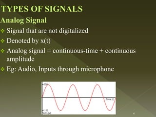
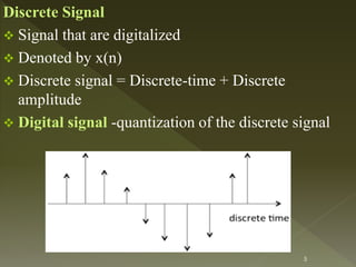
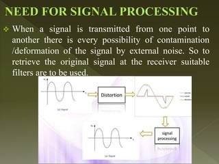
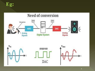
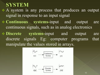
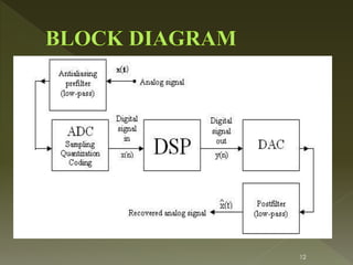
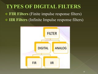
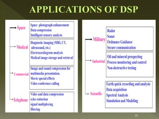
Prepared by
Ms.J.Shiny Christobel
Assistant Professor
Department of ECE
Sri Ramakrishna Institute of Technology, Coimbatore
1
 Introduction to DSP
 Block Diagram
 Filters
 Applications
2
SIGNAL
 A physical quantity varies
with time, space or any
other independent variable
 1-D (Eg: Speech , ECG or
EEG signal)
 2-D (Eg: Image)
 3-D (Eg:Videos)
 Multi dimensional
signal(Eg:Google map)
3
Analog Signal
 Signal that are not digitalized
 Denoted by x(t)
 Analog signal = continuous-time + continuous
amplitude
 Eg: Audio, Inputs through microphone
4
Discrete Signal
 Signal that are digitalized
 Denoted by x(n)
 Discrete signal = Discrete-time + Discrete
amplitude
 Digital signal -quantization of the discrete signal
5
 Energy signal (E=finite and P=infinity)
 Power signal (E=0 and P=finite)
 Causal signal (depends on past and present values)
 Non-causal signal (depends on future values)
 Deterministic signal (Eg: CT or DT signal)
 Random signal (Eg: Noise)
6
 Analysis , interpretation and manipulation of
signals
 Gets an input signal, process it and produces an
output signal.
7
 When a signal is transmitted from one point to
another there is every possibility of contamination
/deformation of the signal by external noise. So to
retrieve the original signal at the receiver suitable
filters are to be used.
8
9
 A system is any process that produces an output
signal in response to an input signal
 Continuous systems-input and output are
continuous signals, such as in analog electronics
 Discrete systems-input and output are
discrete signals Eg: computer programs that
manipulate the values stored in arrays.
10
 Static or Dynamic system
 Linear and Non-linear system (superposition principle)
 Time Varient and time In-varient system
 Causal and non-causal systems
 Stable and unstable system
11
12
13
USES OF FILTERS (Eg:Poor audio, Blurred Image)
 Signal restoration
 Signal separation
TYPES OF FILTERS
14
 Analog filters take the analog signal as input
and process the signal and finally gives the
analog output.
 An analog filter is constructed using resistors,
capacitors, active components etc…
 An analog filter is denoted by a differential
equation. (Laplace tranform)
15
16
 A digital filter processes and generates digital
data. (Z-Transform)
 A digital filter constitutes elements like adder,
multiplier and delay units.
 Digital filters are vastly superior in the level of
performance in comparison to analog filters.
 A digital filter is denoted by a difference equation
 The performance is not influenced by component
ageing, temperature and power variations.
 It is highly immune to noise and relatively stable.
 Transportation and reconfiguration is very easy which
is not true in the case of analog filters.
 Multiple filtering is possible only in digital filters.
 Computational problems are minimum.
17
 Quantization error occurs due to finite word length in
the representation of signals and parameters.
 Digital filters also suffer from Bandwidth problems.
18
 FIR Filters (Finite impulse response filters)
 IIR Filters (Infinite Impulse response filters)
19
 The digital filter whose impulse response is of finite
duration is known as Finite impulse response filter
 The response depends only on the present and past
input samples
 Also called non recursive filters
 It has a finite number of non-zero terms
 FIR filters can be designed with exact linear phase.
 FIR filters are stable
 Round off noise can be eliminated in FIR filters
 DEMERT :The delay of linear phase FIR filters can
create problems in some DSP applications. 20
 The digital filter whose impulse response is of
infinite duration is known as Infinite impulse
response filter.
 The response of an IIR filter is a function of
current and past input signal samples and past
output signal samples.
 It is also called recursive filter.
 It has lesser number of side lobes in the stop-
band.
 The implementation of an IIR filter involves
fewer parameters, less memory requirements and
lower computational complexity
21
 IIR filters do not have linear phase
 not very stable
 Realization of IIR filters is not very easy as
compared to FIR filters
 As it is a recursive filter the number of
coefficients is very large and the memory
requirements are also high
22
23
 In all musical recordings, the sound from instruments is
recorded in studio and then special audio effects are
added by manipulating the recorded musical sounds.
The audio effects are artificially generated using
various DSP techniques.
 the sound recorded in a studio is different and it doesn’t
sound natural.
 So, echoes are simply generated by delay units.
 The direct sound and a single echo appear in K
sampling period latter can be generated by the FIR
filter with the system function
24
25
 To generate multiple echoes separated K
sampling periods we can use an FIR filter with
transfer function
26
 The other special sound effects are flanging and
chorus. The flanging effect is created by feeding the
same musical note to two tape recorders and then
combining their delayed outputs.
 This effect can be simulated using the FIR filter by
periodically varying the delay K(n) between 0 and K.
27
 The chorus effect is achieved when several
musicians are playing the same musical note at the
same time with small changes in the amplitudes and
small timing differences between their sounds.
 A chorus generator can be realized by parallelly
connecting few number of flanging effect filters
28
 IMAGE PROCESSING
Cancer Detection
Fog Removal
 SPEECH PROCESSING
Speech to Text conversion
29
30

Introduction to DSP

  • 1.
    Prepared by Ms.J.Shiny Christobel AssistantProfessor Department of ECE Sri Ramakrishna Institute of Technology, Coimbatore 1
  • 2.
     Introduction toDSP  Block Diagram  Filters  Applications 2
  • 3.
    SIGNAL  A physicalquantity varies with time, space or any other independent variable  1-D (Eg: Speech , ECG or EEG signal)  2-D (Eg: Image)  3-D (Eg:Videos)  Multi dimensional signal(Eg:Google map) 3
  • 4.
    Analog Signal  Signalthat are not digitalized  Denoted by x(t)  Analog signal = continuous-time + continuous amplitude  Eg: Audio, Inputs through microphone 4
  • 5.
    Discrete Signal  Signalthat are digitalized  Denoted by x(n)  Discrete signal = Discrete-time + Discrete amplitude  Digital signal -quantization of the discrete signal 5
  • 6.
     Energy signal(E=finite and P=infinity)  Power signal (E=0 and P=finite)  Causal signal (depends on past and present values)  Non-causal signal (depends on future values)  Deterministic signal (Eg: CT or DT signal)  Random signal (Eg: Noise) 6
  • 7.
     Analysis ,interpretation and manipulation of signals  Gets an input signal, process it and produces an output signal. 7
  • 8.
     When asignal is transmitted from one point to another there is every possibility of contamination /deformation of the signal by external noise. So to retrieve the original signal at the receiver suitable filters are to be used. 8
  • 9.
  • 10.
     A systemis any process that produces an output signal in response to an input signal  Continuous systems-input and output are continuous signals, such as in analog electronics  Discrete systems-input and output are discrete signals Eg: computer programs that manipulate the values stored in arrays. 10
  • 11.
     Static orDynamic system  Linear and Non-linear system (superposition principle)  Time Varient and time In-varient system  Causal and non-causal systems  Stable and unstable system 11
  • 12.
  • 13.
  • 14.
    USES OF FILTERS(Eg:Poor audio, Blurred Image)  Signal restoration  Signal separation TYPES OF FILTERS 14
  • 15.
     Analog filterstake the analog signal as input and process the signal and finally gives the analog output.  An analog filter is constructed using resistors, capacitors, active components etc…  An analog filter is denoted by a differential equation. (Laplace tranform) 15
  • 16.
    16  A digitalfilter processes and generates digital data. (Z-Transform)  A digital filter constitutes elements like adder, multiplier and delay units.  Digital filters are vastly superior in the level of performance in comparison to analog filters.
  • 17.
     A digitalfilter is denoted by a difference equation  The performance is not influenced by component ageing, temperature and power variations.  It is highly immune to noise and relatively stable.  Transportation and reconfiguration is very easy which is not true in the case of analog filters.  Multiple filtering is possible only in digital filters.  Computational problems are minimum. 17
  • 18.
     Quantization erroroccurs due to finite word length in the representation of signals and parameters.  Digital filters also suffer from Bandwidth problems. 18
  • 19.
     FIR Filters(Finite impulse response filters)  IIR Filters (Infinite Impulse response filters) 19
  • 20.
     The digitalfilter whose impulse response is of finite duration is known as Finite impulse response filter  The response depends only on the present and past input samples  Also called non recursive filters  It has a finite number of non-zero terms  FIR filters can be designed with exact linear phase.  FIR filters are stable  Round off noise can be eliminated in FIR filters  DEMERT :The delay of linear phase FIR filters can create problems in some DSP applications. 20
  • 21.
     The digitalfilter whose impulse response is of infinite duration is known as Infinite impulse response filter.  The response of an IIR filter is a function of current and past input signal samples and past output signal samples.  It is also called recursive filter.  It has lesser number of side lobes in the stop- band.  The implementation of an IIR filter involves fewer parameters, less memory requirements and lower computational complexity 21
  • 22.
     IIR filtersdo not have linear phase  not very stable  Realization of IIR filters is not very easy as compared to FIR filters  As it is a recursive filter the number of coefficients is very large and the memory requirements are also high 22
  • 23.
  • 24.
     In allmusical recordings, the sound from instruments is recorded in studio and then special audio effects are added by manipulating the recorded musical sounds. The audio effects are artificially generated using various DSP techniques.  the sound recorded in a studio is different and it doesn’t sound natural.  So, echoes are simply generated by delay units.  The direct sound and a single echo appear in K sampling period latter can be generated by the FIR filter with the system function 24
  • 25.
  • 26.
     To generatemultiple echoes separated K sampling periods we can use an FIR filter with transfer function 26
  • 27.
     The otherspecial sound effects are flanging and chorus. The flanging effect is created by feeding the same musical note to two tape recorders and then combining their delayed outputs.  This effect can be simulated using the FIR filter by periodically varying the delay K(n) between 0 and K. 27
  • 28.
     The choruseffect is achieved when several musicians are playing the same musical note at the same time with small changes in the amplitudes and small timing differences between their sounds.  A chorus generator can be realized by parallelly connecting few number of flanging effect filters 28
  • 29.
     IMAGE PROCESSING CancerDetection Fog Removal  SPEECH PROCESSING Speech to Text conversion 29
  • 30.