Downloaded 561 times


![ Introduction to Speech Processing | Ricardo Gutierrez-Osuna | CSE@TAMU, chapter 10 of [Taylor, TTS synthesis, 2009].
An Introduction to Digital Filters,application note,january1999, Intersil and Design is a trademark of Intersil Corporation. |
Copyright©Intersil Corporation 2000
Digital Filters and Z Transforms,Copyright © Richard C. Bailey and David M. Harrison, 1998, 1999
http://en.wikipedia.org/wiki/Digital_filter](https://image.slidesharecdn.com/pdigitalfilters-130421135713-phpapp01/85/digital-filters-13-320.jpg)


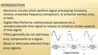
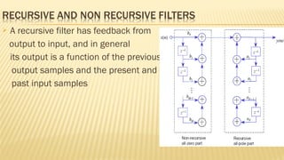
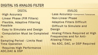
This document discusses digital filters. It begins by defining digital filters as electronic circuits that perform signal processing functions by removing or enhancing certain frequency components of a sampled, discrete-time signal. It then outlines four basic types of ideal digital filters defined by their magnitude responses. The document also discusses different classifications of digital filters based on characteristics like linearity, time-invariance, and structure. It provides examples of common filter structures like direct form, cascade form, and parallel form. Finally, it briefly compares digital and analog filters, noting advantages and disadvantages of each.