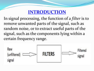
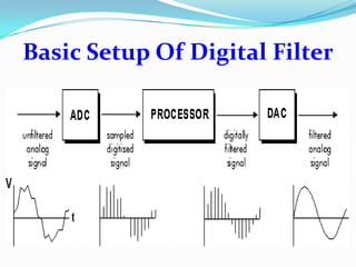
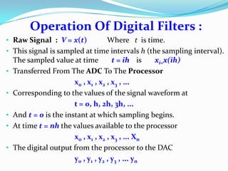
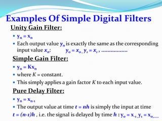
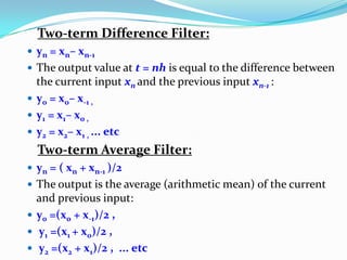
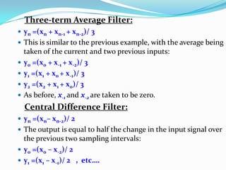
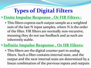
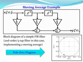
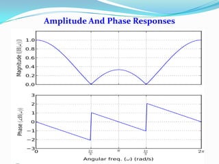
Digital filters can remove unwanted noise from signals or extract useful frequency components. They operate by sampling an analog signal, processing the digital values, and converting back to analog. Finite impulse response (FIR) filters use weighted sums of past inputs for outputs and are inherently stable without feedback. Infinite impulse response (IIR) filters use feedback, with outputs and next states determined by inputs and past outputs. Common filters include moving average filters and filters that introduce gain, delay, or differences between signal values. Design involves selecting coefficients for desired frequency responses. Stability depends on pole locations within the unit circle. Digital filters find applications in communications, audio, imaging, and other areas.
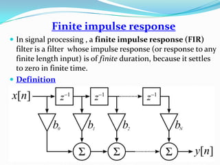
![Impulse response
The impulse response h[n]can be calculated if we set x[n]= δ[n]in
the above relation, where δ[n] is the Kronecker delta impulse. The
impulse response for an FIR filter then becomes the set of
coefficients , as follows
For n=0 to N
The Z-transform of the impulse response
FIR filters are clearly bounded - input
bounded-output (BIBO) stable, since
the output is a sum of a finite number of
finite multiples of the input values, so can
be no greater than](https://image.slidesharecdn.com/dssp-130808204611-phpapp02/85/Dss-11-320.jpg)
![Transfer Function Derivation
P is the feedforward filter order
bi are the feedforward filter coefficients
Q is the feedback filter order
ai are the feedback filter coefficients
x[n] is the input signal
y[n] is the output signal.
When Rearranged](https://image.slidesharecdn.com/dssp-130808204611-phpapp02/85/Dss-17-320.jpg)