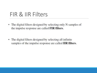
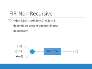
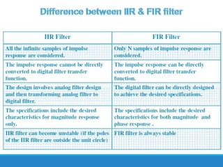
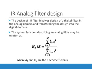
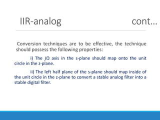
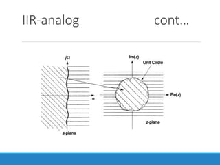
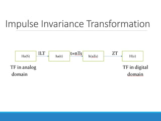
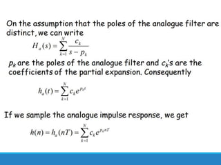
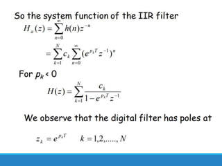
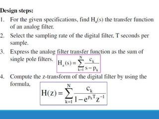
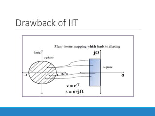
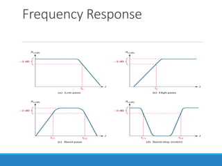
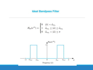
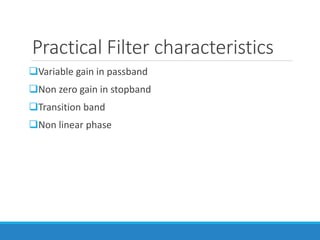
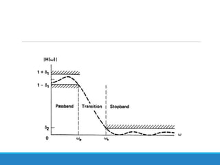
UNIT 2
INFINITEIMPULSERESPONSE
FILTERS
What is a filter?
To attenuate one frequency or a range of frequencies out of mix of
different frequencies.
Selectively filtering one frequency or range of frequencies.
An LTI system performs filtering process among the various components
at its input.
It acts a frequency shaping filter.
Applications of filters
Electronics and Telecommunication
Radio
Television
Audio Recording
Computer Graphics
Radar
Sonar
Main uses of filters
Signal Separation
 eg)measure the heart beat of baby’s heart in womb-
corrupted by breathing and heartbeat of mother.
Signal Restoration
 eg)audio recording with poor equipment-shaky
camera-blurred image
Removal of undesirable noise
Signal detection
Spectral analysis
Main Classification of Filters
Analog Filter-process only analog signals,x(t),y(t)
Digital Filter-process only digital signals,x(n),y(n)
Ideal filter characteristics
The filters have a constant gain(unity gain) passband
characteristics and zero gain in their stopband.
Linear phase response.
Depending on the
characteristic…
LPF
HPF
BPF
BSF
Frequency Response
Practical Filter characteristics
Variable gain in passband
Non zero gain in stopband
Transition band
Non linear phase
Classification of Digital Filters
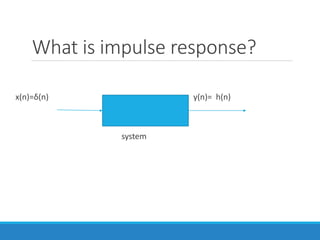
FIR-Finite Impulse Response
-impulse response h(n) is of finite duration
Eg: h(n)={1,2,3,4}
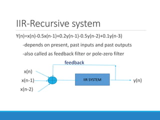
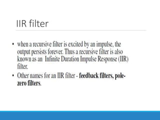
IIR-Infinite Impulse Response
-impulse response h(n) is of infinite duration
Eg: h(n)=[(1/2)^n -(0.1)^n]u(n)
What is impulse response?
x(n)=δ(n) sys y(n)= h(n)
system
FIR & IIR Filters
FIR-Non Recursive
Y(n)=x(n)-0.5x(n-1)+0.2x(n-2)-0.1x(n-3)
-depends on present and past inputs
-no memory
x(n)
x(n-1) y(n)
x(n-2)
FIR SYSTEM
IIR-Recursive system
Y(n)=x(n)-0.5x(n-1)+0.2y(n-1)-0.5y(n-2)+0.1y(n-3)
-depends on present, past inputs and past outputs
-also called as feedback filter or pole-zero filter
feedback
x(n)
x(n-1) y(n)
x(n-2)
IIR SYSTEM
IIR filter
IIR Analog filter design
 The design of IIR filter involves design of a digital filter in
the analog domain and transforming the design into the
digital domain.
 The system function describing an analog filter may be
written as
where 𝑎𝑘 and 𝑏𝑘 are the filter coefficients.
IIR-analog cont…
Conversion techniques are to be effective, the technique
should possess the following properties:
i) The 𝑗Ω axis in the s-plane should map onto the unit
circle in the z-plane.
ii) The left half plane of the s-plane should map inside of
the unit circle in the z-plane to convert a stable analog filter into a
stable digital filter.
IIR-analog cont…
IIR digital filter design
Impulse Invariance Transformation
Bilinear Transformation
Approximation Derivatives
Matched Z Transform
Impulse Invariance Transformation
Drawback of IIT
Drawback of IIT
IIR filter
IIR filter
IIR filter
IIR filter
IIR filter
IIR filter

IIR filter