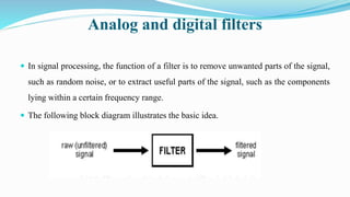
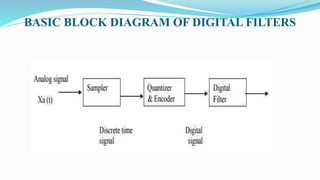
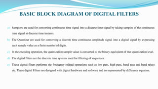
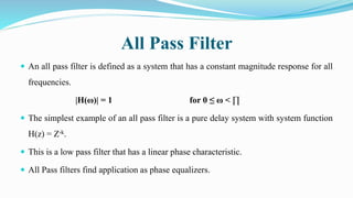
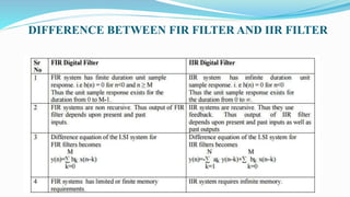
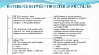
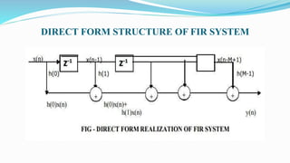
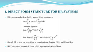
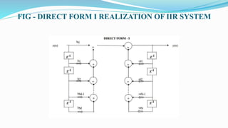
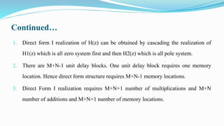
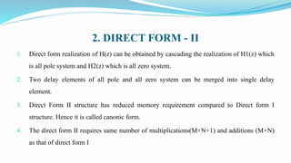
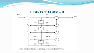
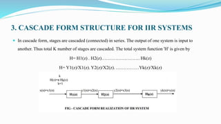
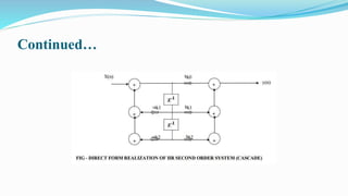
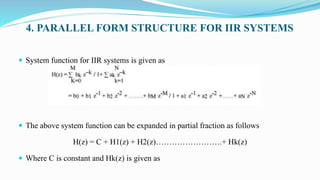
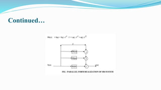
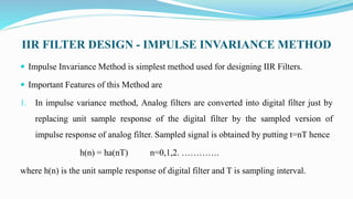
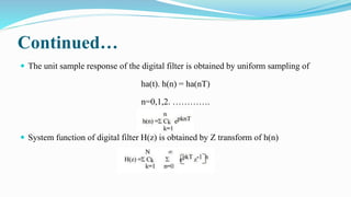
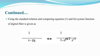
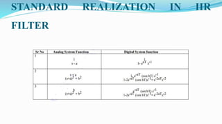
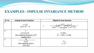
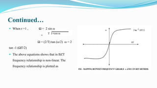
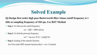
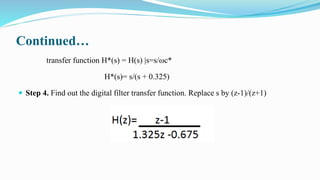
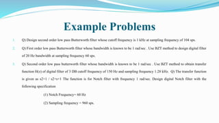
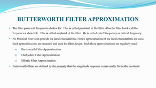
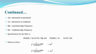
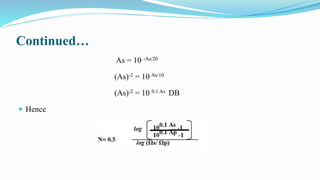
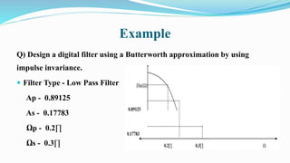
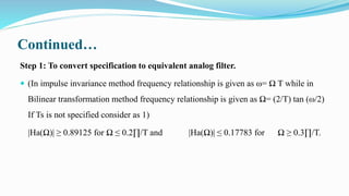
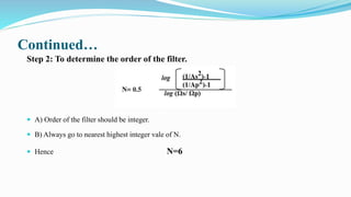
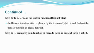
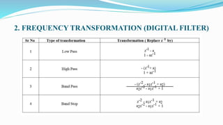
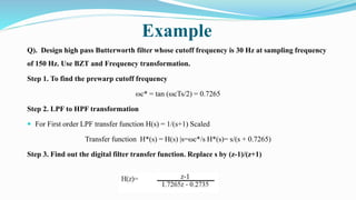
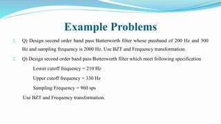
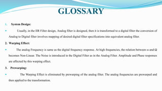
SlideShare a Scribd company logo
By
T.SELVALAKSHMI,B.E.,
UNIT II
INFINITE IMPULSE RESPONSE
FILTERS
INTRODUCTION
INTRODUCTION
 To remove or to reduce strength of unwanted signal like noise and to improve the quality of
required signal filtering process is used.
 To use the channel full bandwidth we mix up two or more signals on transmission side and on
receiver side we would like to separate it out in efficient way.
 Hence filters are used.
 Thus the digital filters are mostly used in,
1. Removal of undesirable noise from the desired signals
2. Equalization of communication channels
3. Signal detection in radar, sonar and communication
4. Performing spectral analysis of signals
Analog and digital filters
 In signal processing, the function of a filter is to remove unwanted parts of the signal,
such as random noise, or to extract useful parts of the signal, such as the components
lying within a certain frequency range.
 The following block diagram illustrates the basic idea.
Analog and digital filters
 There are two main kinds of filter,
1. Analog filter
2. Digital filter
 They are quite different in their physical makeup and in how they work.
 An analog filter uses analog electronic circuits made up from components such
as resistors, capacitors and op amps to produce the required filtering effect.
Analog and digital filters
 Such filter circuits are widely used in such applications as noise reduction, video signal
enhancement, graphic equalizers in hi-fi systems, and many other areas.
 In analog filters the signal being filtered is an electrical voltage or current which is the direct
analogue of the physical quantity involved.
 A digital filter uses a digital processor to perform numerical calculations on sampled values
of the signal.
 The processor may be a general-purpose computer such as a PC, or a specialized DSP chip.
 The analog input signal must first be sampled and digitized using an ADC.
Analog and digital filters
 The resulting binary numbers, representing successive sampled values of the input signal, are
transferred to the processor, which carries out numerical calculations on them.
 These calculations typically involve multiplying the input values by constants and adding the products
together.
 If necessary, the results of these calculations, which now represent sampled values of the filtered
signal, are output through a DAC to convert the signal back to analog form.
 In a digital filter, the signal is represented by a sequence of numbers, rather than a voltage or current.
 The following diagram shows the basic setup of such a system.
Basic Setup of DSP system
BASIC BLOCK DIAGRAM OF DIGITAL FILTERS
a) Samplers are used for converting continuous time signal into a discrete time signal by taking samples of the continuous
time signal at discrete time instants.
b) The Quantizer are used for converting a discrete time continuous amplitude signal into a digital signal by expressing
each sample value as a finite number of digits.
c) In the encoding operation, the quantization sample value is converted to the binary equivalent of that quantization level.
d) The digital filters are the discrete time systems used for filtering of sequences.
e) These digital filters performs the frequency related operations such as low pass, high pass, band pass and band reject
etc. These digital Filters are designed with digital hardware and software and are represented by difference equation.
DIFFERENCE BETWEEN ANALOG FILTER AND
DIGITAL FILTER
Analog Filter
1. Analog filters are used for filtering analog signals.
2. Analog filters are designed with various components like resistor, inductor and
capacitor
3. Analog filters less accurate & because of component tolerance of active
components & more sensitive to environmental changes.
4. Less flexible
5. Filter representation is in terms of system components.
6. An analog filter can only be changed by redesigning the filter circuit.
Digital Filter
1. Digital filters are used for filtering digital sequences.
2. Digital Filters are designed with digital hardware like FF, counters shift registers, ALU and software s like C
or assembly language.
3. Digital filters are less sensitive to the environmental changes, noise and disturbances. Thus periodic
calibration can be avoided. Also they are extremely stable.
4. These are most flexible as software programs & control programs can be easily modified. Several input
signals can be filtered by one digital filter.
5. Digital filters are represented by the difference equation.
6. A digital filter is programmable, i.e. its operation is determined by a program stored in the processor's
memory. This means the digital filter can easily be changed without affecting the circuitry (hardware).
FILTER TYPES AND IDEAL FILTER
CHARACTERISTIC
 Filters are usually classified according to their frequency-domain characteristic
as,
1. Low pass filters
2. High pass filters
3. Band pass filters
4. Band stop filters
1. Low Pass Filter
 A low pass filter is made up of a passband and a stopband, where the lower
frequencies of the input signal are passed through while the higher frequencies
are attenuated.
2. High Pass Filter
 A high pass filter is made up of a stopband and a passband where the lower
frequencies of the input signal are attenuated while the higher frequencies are
passed.
3. Band Pass Filter
 A bandpass filter is made up of two stopbands and one passband so that the
lower and higher frequencies of the input signal are attenuated while the
intervening frequencies are passed.
4. Band Stop Filter
 A band stop filter is made up of two passbands and one stopband so that the lower
and higher frequencies of the input signal are passed while the intervening
frequencies are attenuated.
 An idealized band stop filter frequency response has the following,
Multi-Pass Filter
 A multi-pass filter begins with a stopband followed by more than one
passband.
 By default, a multi-pass filter in Digital Filter Designer consists of three
passbands and four stopbands.
 The frequencies of the input signal at the stopbands are attenuated while those
at the passbands are passed.
Multi-Stop Filter
 A multi-stop filter begins with a passband followed by more than one
stopband.
 By default, a multi-stop filter in Digital Filter Designer consists of three
passbands and two stopbands.
All Pass Filter
 An all pass filter is defined as a system that has a constant magnitude response for all
frequencies.
|H(ω)| = 1 for 0 ≤ ω < ∏
 The simplest example of an all pass filter is a pure delay system with system function
H(z) = Z-k.
 This is a low pass filter that has a linear phase characteristic.
 All Pass filters find application as phase equalizers.
IDEAL FILTERCHARACTERISTIC
1. Ideal filters have a constant gain passband characteristic and zero gain in
their stop band.
2. Ideal filters have a linear phase characteristic within their passband.
3. Ideal filters also have constant magnitude characteristic.
4. Ideal filters are physically unrealizable.
TYPES OF DIGITAL FILTER
 Digital filters are of two types.
1. Finite Impulse Response Digital Filter(FIR)
2. Infinite Impulse Response Digital Filter(IIR)
DIFFERENCE BETWEEN FIR FILTER AND IIR FILTER
FIR Digital Filter
 FIR system has finite duration unit sample response. i.e h(n) = 0 for n<0 and n ≥ M Thus the unit
sample response exists for the duration from 0 to M-1.
 FIR systems are non recursive. Thus output of FIR filter depends upon present and past inputs.
 Difference equation of the LSI system for FIR filters becomes introduced in the signal by the filter.
 The effect of using finite word length to implement filter, noise and quantization errors are less severe
in FIR than in IIR.
STRUCTURES FOR FIR SYSTEMS
 FIR Systems are represented in four different ways
1. Direct Form Structures
2. Cascade Form Structure
3. Frequency-Sampling Structures
4. Lattice structures.
1. DIRECT FORM STRUCTURE OF FIR SYSTEM
 The convolution of h(n) and x(n) for FIR systems can be written as
M-1
y(n)=∑ h(k) x(n–k)
k=0
 The above equation can be expanded as,
Y(n)= h(0) x(n) + h(1) x(n-1) + h(2) x(n-2) + …………… + h(M-1) x(n-M+1)
 Implementation of direct form structure of FIR filter is based upon the above
equation.
DIRECT FORM STRUCTURE OF FIR SYSTEM
Continued…
1. There are M-1 unit delay blocks. One unit delay block requires one memory
location.
2. Hence direct form structure requires M-1 memory locations.
3. The multiplication of h(k) and x(n-k) is performed for 0 to M-1 terms. Hence M
multiplications and M-1 additions are required.
4. Direct form structure is often called as transversal or tapped delay line filter.
2. CASCADE FORM STRUCTURE OF FIR SYSTEM
 In cascade form, stages are cascaded (connected) in series. The output of one system
 is input to another. Thus total K number of stages are cascaded. The total system function 'H' is given
by H= H1(z) . H2(z)……………………. Hk(z)
H= Y1(z)/X1(z). Y2(z)/X2(z). ……………Yk(z)/Xk(z)
Continued…
 Each H1(z), H2(z)… etc is a second order section and it is realized by the direct form as shown in
below figure.
 System function for FIR systems
 Expanding the above terms we have
H(z)= H1(z) . H2(z)……………………. Hk(z)
Continued…
IIR Digital Filter
1. IIR system has infinite duration unit sample response. i. e h(n) = 0 for n<0 Thus the
unit sample response exists for the duration from 0 to ∞.
2. IIR systems are recursive. Thus they use feedback. Thus output of IIR filter depends
upon present and past inputs as well as past outputs
3. Difference equation of the LSI system for IIR filters becomes
4. IIR system requires infinite memory.
STRUCTURES FOR IIR SYSTEMS
 IIR Systems are represented in four different ways
1. Direct Form Structures Form I and Form II
2. Cascade Form Structure
3. Parallel Form Structure
4. Lattice and Lattice-Ladder structure.
1. DIRECT FORM STRUCTURE FOR IIR SYSTEMS
 IIR systems can be described by a generalized equations as
 Overall IIR system can be realized as cascade of two function H1(z) and H2(z). Here
 H1(z) represents zeros of H(z) and H2(z) represents all poles of H(z).
FIG - DIRECT FORM I REALIZATION OF IIR SYSTEM
Continued…
1. Direct form I realization of H(z) can be obtained by cascading the realization of
H1(z) which is all zero system first and then H2(z) which is all pole system.
2. There are M+N-1 unit delay blocks. One unit delay block requires one memory
location. Hence direct form structure requires M+N-1 memory locations.
3. Direct Form I realization requires M+N+1 number of multiplications and M+N
number of additions and M+N+1 number of memory locations.
2. DIRECT FORM - II
1. Direct form realization of H(z) can be obtained by cascading the realization of H1(z) which
is all pole system and H2(z) which is all zero system.
2. Two delay elements of all pole and all zero system can be merged into single delay
element.
3. Direct Form II structure has reduced memory requirement compared to Direct form I
structure. Hence it is called canonic form.
4. The direct form II requires same number of multiplications(M+N+1) and additions (M+N)
as that of direct form I
2. DIRECT FORM - II
3. CASCADE FORM STRUCTURE FOR IIR SYSTEMS
 In cascade form, stages are cascaded (connected) in series. The output of one system is input to
another. Thus total K number of stages are cascaded. The total system function 'H' is given by
H= H1(z) . H2(z)……………………. Hk(z)
H= Y1(z)/X1(z). Y2(z)/X2(z). ……………Yk(z)/Xk(z)
Continued…
 Each H1(z), H2(z)… etc. is a second order section and it is realized by the direct form
as shown in below figure.
 System function for IIR systems
 Thus Direct form of second order IIR system is shown as
Continued…
4. PARALLEL FORM STRUCTURE FOR IIR SYSTEMS
 System function for IIR systems is given as
 The above system function can be expanded in partial fraction as follows
H(z) = C + H1(z) + H2(z)…………………….+ Hk(z)
 Where C is constant and Hk(z) is given as
Continued…
IIR FILTER DESIGN
1. IMPULSE INVARIANCE
2. BILINEAR TRANSFORMATION
3. BUTTERWORTH APPROXIMATION
IIR FILTER DESIGN - IMPULSE INVARIANCE METHOD
 Impulse Invariance Method is simplest method used for designing IIR Filters.
 Important Features of this Method are
1. In impulse variance method, Analog filters are converted into digital filter just by
replacing unit sample response of the digital filter by the sampled version of
impulse response of analog filter. Sampled signal is obtained by putting t=nT hence
h(n) = ha(nT) n=0,1,2. ………….
where h(n) is the unit sample response of digital filter and T is sampling interval.
Continued…
2. But the main disadvantage of this method is that it does not correspond to simple algebraic mapping
of S plane to the Z plane. Thus the mapping from analog frequency to digital frequency is many to
one. The segments (2k-1)∏/T ≤ Ω ≤ (2k+1) ∏/T of j Ω axis are all mapped on the unit circle
∏≤ω≤∏. This takes place because of sampling.
3. Frequency aliasing is second disadvantage in this method. Because of frequency aliasing, the
frequency response of the resulting digital filter will not be identical to the original analog frequency
response.
4. Because of these factors, its application is limited to design low frequency filters like LPF or a
limited class of band pass filters.
RELATIONSHIP BETWEEN Z PLANE AND S
PLANE
 Z is represented as rejω in polar form and relationship between Z plane and S plane is given as Z=eST where s= σ
+ j Ω.
 Here we have three condition
1. If σ = 0 then r=1
2. If σ < 0 then 0 < r < 1
3. If σ > 0 then r> 1
Continued…
 Thus
1. Left side of s-plane is mapped inside the unit circle.
2. Right side of s-plane is mapped outside the unit circle.
3. jΩ axis is in s-plane is mapped on the unit circle.
CONVERSION OF ANALOG FILTER INTO DIGITAL
FILTER
 Let the system function of analog filter is n
 where pk are the poles of the analog filter and ck are the coefficients of partial fraction expansion. The
impulse response of the analog filter ha(t) is obtained by inverse Laplace transform and given as
Continued…
 The unit sample response of the digital filter is obtained by uniform sampling of
ha(t). h(n) = ha(nT)
n=0,1,2. ………….
 System function of digital filter H(z) is obtained by Z transform of h(n)
Continued…
 Using the standard relation and comparing equation (1) and (4) system function
of digital filter is given as
STANDARD REALIZATION IN IIR
FILTER
EXAMPLES - IMPULSE INVARIANCE METHOD
IIR FILTER DESIGN - BILINEAR TRANSFORMATION
METHOD (BZT)
 The method of filter design by impulse invariance suffers from aliasing.
 Hence in order to overcome this drawback Bilinear transformation method is
designed.
 In analogue domain frequency axis is an infinitely long straight line while
sampled data z plane it is unit circle radius.
 The bilinear transformation is the method of squashing the infinite straight
analog frequency axis so that it becomes finite
Important Features of Bilinear Transform Method
1. Bilinear transformation method (BZT) is a mapping from analog S plane to digital Z plane. This conversion maps analog
poles to digital poles and analog zeros to digital zeros. Thus all poles and zeros are mapped.
2. This transformation is basically based on a numerical integration techniques used to simulate an integrator of analog
filter.
3. There is one to one correspondence between continuous time and discrete time frequency points. Entire range in Ω is
mapped only once into the range -∏≤ω≤∏.
4. Frequency relationship is non-linear. Frequency warping or frequency compression is due to non-linearity. Frequency
warping means amplitude response of digital filter is expanded at the lower frequencies and compressed at the higher
frequencies in comparison of the analog filter.
5. But the main disadvantage of frequency warping is that it does change the shape of the desired filter frequency response.
In particular, it changes the shape of the transition bands.
CONVERSION OF ANALOG FILTER INTO DIGITAL
FILTER
 Z is represented as rejω in polar form and relationship between Z plane and S plane in
BZT method is given as
Continued…
 Comparing the above equation with S= σ + j Ω. We have
 Here we have three condition
1. If σ < 0 then 0 < r < 1
2. If σ > 0 then r > 1
3. If σ = 0 then r=1
Continued…
 When r =1 , Ω = 2 sin ω
=
Ω = (2/T) tan (ω/2) ω = 2
tan -1 (ΩT/2)
 The above equations shows that in BZT
frequency relationship is non-linear. The
frequency relationship is plotted as
DIFFERENCE - IMPULSE INVARIANCE Vs BILINEAR
TRANSFORMATION
LPF AND HPFANALOG BUTTERWORTH FILTER
TRANSFER FUNCTION
METHOD FOR DESIGNING DIGITAL FILTERS
USING BZT
Step 1. Find out the value of ωc *:
 ωc *= ω c (2/T) tan (ωc Ts/2)
Step 2. Find out the value of frequency scaled analog transfer function:
 Normalized analog transfer function is frequency scaled by replacing s by s/ωp*.
Step 3. Convert into digital filter
 Apply BZT. i.e Replace s by the ((z-1)/(z+1)). And find out the desired transfer function of
digital function.
Solved Example
Q) Design first order high pass Butterworth filter whose cutoff frequency is 1
kHz at sampling frequency of 104 sps. Use BZT Method
 Step 1. To find out the cutoff frequency
ωc = 2∏f = 2000 rad/sec
 Step 2. To find the prewarp frequency
ωc* = tan (ωc Ts/2) = tan(∏/10)
 Step 3. Scaling of the transfer function
For First order HPF transfer function H(s) = s/(s+1) Scaled
Continued…
transfer function H*(s) = H(s) |s=s/ωc*
H*(s)= s/(s + 0.325)
 Step 4. Find out the digital filter transfer function. Replace s by (z-1)/(z+1)
Example Problems
1. Q) Design second order low pass Butterworth filter whose cutoff frequency is 1 kHz at sampling frequency of 104 sps.
2. Q) First order low pass Butterworth filter whose bandwidth is known to be 1 rad/sec . Use BZT method to design digital filter
of 20 Hz bandwidth at sampling frequency 60 sps.
3. Q) Second order low pass butterworth filter whose bandwidth is known to be 1 rad/sec . Use BZT method to obtain transfer
function H(z) of digital filter of 3 DB cutoff frequency of 150 Hz and sampling frequency 1.28 kHz. Q) The transfer function
is given as s2+1 / s2+s+1 The function is for Notch filter with frequency 1 rad/sec. Design digital Notch filter with the
following specification
(1) Notch Frequency= 60 Hz
(2) Sampling frequency = 960 sps.
BUTTERWORTH FILTER APPROXIMATION
 The filter passes all frequencies below Ωc. This is called passband of the filter. Also the filter blocks all the
frequencies above Ωc. This is called stopband of the filter. Ωc is called cutoff frequency or critical frequency.
 No Practical filters can provide the ideal characteristic. Hence approximation of the ideal characteristic are used.
Such approximations are standard and used for filter design. Such three approximations are regularly used.
a) Butterworth Filter Approximation
b) Chebyshev Filter Approximation
c) Elliptic Filter Approximation
 Butterworth filters are defined by the property that the magnitude response is maximally flat in the passband.
Continued…
Continued…
 The squared magnitude function for an analog Butterworth filter is of the form.
 N indicates order of the filter and Ωc is the cutoff frequency (-3DB frequency). At s =
j Ω magnitude of H(s) and H(-s) is same hence
 To find poles of H(s). H(-s) , find the roots of denominator in above equation.
Continued…
FREQUENCY RESPONSE CHARACTERISTIC
 The frequency response characteristic of |Ha(Ω)|2 is as shown.
 As the order of the filter N increases, the Butterworth filter characteristic is
more close to the ideal characteristic.
 Thus at higher orders like N=16 the Butterworth filter characteristic closely
approximate ideal filter characteristic.
 Thus an infinite order filter (N= ∞) is required to get ideal characteristic.
Continued…
Continued…
 Ap= attenuation in passband.
 As= attenuation in stopband.
 Ωp = passband edge frequency
 Ωs = stopband edge frequency
 Specification for the filter is
|Ha(Ω)| ≥ Ap for Ω ≤ Ωp and |Ha(Ω)| ≤ As for Ω ≥ Ωs.
 Hence we have
Continued…
 To determine the poles and order of analog filter consider equalities.
 Hence order of the filter (N) is calculated as
Continued…
 And cutoff frequency Ωc is calculated as
 If As and Ap values are given in DB then
As (DB) = - 20 log As
log As = -As /20
Continued…
As = 10 -As/20
(As)-2 = 10 As/10
(As)-2 = 10 0.1 As DB
 Hence
Example
Q) Design a digital filter using a Butterworth approximation by using
impulse invariance.
 Filter Type - Low Pass Filter
Ap - 0.89125
As - 0.17783
Ωp - 0.2∏
Ωs - 0.3∏
Continued…
Step 1: To convert specification to equivalent analog filter.
 (In impulse invariance method frequency relationship is given as ω= Ω T while in
Bilinear transformation method frequency relationship is given as Ω= (2/T) tan (ω/2)
If Ts is not specified consider as 1)
|Ha(Ω)| ≥ 0.89125 for Ω ≤ 0.2∏/T and |Ha(Ω)| ≤ 0.17783 for Ω ≥ 0.3∏/T.
Continued…
Step 2: To determine the order of the filter.
N= 5.88
 A) Order of the filter should be integer.
 B) Always go to nearest highest integer vale of N.
 Hence N=6
Continued…
Step 3: To find out the cutoff frequency (-3DB frequency)
Cutoff frequency Ωc = 0.7032
Step 4: To find out the poles of analog filter system function.
Pk = + Ωc e j(N+2k+1) ∏ / 2N
 As N=6 the value of k = 0,1,2,3,4,5.
Continued…
Continued…
 For stable filter all poles lying on the left side of s plane is selected. Hence
S1 = -0.182 + j 0.679 S1* = -0.182 - j 0.679
S2 = -0.497 + j 0.497 S2* = -0.497 - j 0.497
S3 = -0.679 + j 0.182 S3* = -0.679 - j 0.182
Step 5: To determine the system function (Analog Filter)
Continued…
 Hence
Continued…
Step 6: To determine the system function (Digital Filter)
 (In Bilinear transformation replace s by the term ((z-1)/(z+1)) and find out the
transfer function of digital function)
Step 7: Represent system function in cascade form or parallel form if asked.
Example Problems
1. Q) Given for low pass Butterworth filter Ap= -1 db at 0.2∏ As= -15 db at 0.3∏ 1)
Calculate N and Pole location 2) Design digital filter using BZT method.
2. Q) Obtain transfer function of a low pass digital filter meeting specifications Cutoff
0-60Hz Stopband > 85Hz Stopband attenuation > 15 db Sampling frequency= 256
Hz . use Butterworth characteristic.
3. Q) Design second order low pass Butterworth filter whose cutoff frequency is 1
kHz at sampling frequency of 104 sps. Use BZT and Butterworth approximation.
FREQUENCY TRANSFORMATION
 When the cutoff frequency Ωc of the low pass filter is equal to 1 then it is
called normalized filter.
 Frequency transformation techniques are used to generate High pass filter,
Bandpass and bandstop filter from the lowpass filter system function.
1. FREQUENCY TRANSFORMATION (ANALOG FILTER)
2. FREQUENCY TRANSFORMATION (DIGITAL FILTER)
Example
Q). Design high pass Butterworth filter whose cutoff frequency is 30 Hz at sampling frequency
of 150 Hz. Use BZT and Frequency transformation.
Step 1. To find the prewarp cutoff frequency
ωc* = tan (ωcTs/2) = 0.7265
Step 2. LPF to HPF transformation
 For First order LPF transfer function H(s) = 1/(s+1) Scaled
Transfer function H*(s) = H(s) |s=ωc*/s H*(s)= s/(s + 0.7265)
Step 3. Find out the digital filter transfer function. Replace s by (z-1)/(z+1)
Example Problems
1. Q) Design second order band pass Butterworth filter whose passband of 200 Hz and 300
Hz and sampling frequency is 2000 Hz. Use BZT and Frequency transformation.
2. Q) Design second order band pass Butterworth filter which meet following specification
Lower cutoff frequency = 210 Hz
Upper cutoff frequency = 330 Hz
Sampling Frequency = 960 sps
Use BZT and Frequency transformation.
GLOSSARY
1. System Design:
 Usually, in the IIR Filter design, Analog filter is designed, then it is transformed to a digital filter the conversion of
Analog to Digital filter involves mapping of desired digital filter specifications into equivalent analog filter.
2. Warping Effect:
 The analog Frequency is same as the digital frequency response. At high frequencies, the relation between ω and Ω
becomes Non-Linear. The Noise is introduced in the Digital Filter as in the Analog Filter. Amplitude and Phase responses
are affected by this warping effect.
3. Prewarping:
 The Warping Effect is eliminated by prewarping of the analog filter. The analog frequencies are prewarped and
then applied to the transformation.
Continued…
4. Infinite Impulse Response:
 Infinite Impulse Response filters are a Type of Digital Filters which has infinite impulse
response. This type of Filters are designed from analog filters. The Analog filters are then
transformed to Digital Domain.
5. Bilinear Transformation Method:
 In Bilinear transformation method the transform of filters from Analog to Digital is
carried out in a way such that the Frequency transformation produces a Linear relationship
between Analog and Digital Filters.
Continued…
6. Filter:
 A filter is one which passes the required band of signals and stops the other
unwanted band of frequencies.
7. Pass band:
 The Band of frequencies which is passed through the filter is termed as passband.
8. Stopband:
 The band of frequencies which are stopped are termed as stop band.

More Related Content

What's hot

Windowing techniques of fir filter design
Windowing techniques of fir filter designWindowing techniques of fir filter design
Windowing techniques of fir filter design
Rohan Nagpal
 
Sampling Theorem
Sampling TheoremSampling Theorem
Sampling Theorem
Dr Naim R Kidwai
 
Computing DFT using Matrix method
Computing DFT using Matrix methodComputing DFT using Matrix method
Computing DFT using Matrix method
Sarang Joshi
 
Circular Convolution
Circular ConvolutionCircular Convolution
Circular Convolution
Sarang Joshi
 
DSP_2018_FOEHU - Lec 03 - Discrete-Time Signals and Systems
DSP_2018_FOEHU - Lec 03 - Discrete-Time Signals and SystemsDSP_2018_FOEHU - Lec 03 - Discrete-Time Signals and Systems
DSP_2018_FOEHU - Lec 03 - Discrete-Time Signals and Systems
Amr E. Mohamed
 
DSP_2018_FOEHU - Lec 02 - Sampling of Continuous Time Signals
DSP_2018_FOEHU - Lec 02 - Sampling of Continuous Time SignalsDSP_2018_FOEHU - Lec 02 - Sampling of Continuous Time Signals
DSP_2018_FOEHU - Lec 02 - Sampling of Continuous Time Signals
Amr E. Mohamed
 
Broadside array vs end fire array
Broadside array vs end fire arrayBroadside array vs end fire array
Broadside array vs end fire array
AJAL A J
 
Digital Filters Part 1
Digital Filters Part 1Digital Filters Part 1
Digital Filters Part 1
Premier Farnell
 
Circular convolution Using DFT Matlab Code
Circular convolution Using DFT Matlab CodeCircular convolution Using DFT Matlab Code
Circular convolution Using DFT Matlab Code
Bharti Airtel Ltd.
 
Overview of sampling
Overview of samplingOverview of sampling
Overview of sampling
Sagar Kumar
 
Source coding theorem
Source coding theoremSource coding theorem
Source coding theorem
priyadharshini murugan
 
Design of FIR filters
Design of FIR filtersDesign of FIR filters
Design of FIR filters
op205
 
Advanced Topics In Digital Signal Processing
Advanced Topics In Digital Signal ProcessingAdvanced Topics In Digital Signal Processing
Advanced Topics In Digital Signal Processing
Jim Jenkins
 
Pulse Modulation ppt
Pulse Modulation pptPulse Modulation ppt
Pulse Modulation ppt
sanjeev2419
 
DSP_2018_FOEHU - Lec 07 - IIR Filter Design
DSP_2018_FOEHU - Lec 07 - IIR Filter DesignDSP_2018_FOEHU - Lec 07 - IIR Filter Design
DSP_2018_FOEHU - Lec 07 - IIR Filter Design
Amr E. Mohamed
 
DSP Lab Manual (10ECL57) - VTU Syllabus (KSSEM)
DSP Lab Manual (10ECL57) - VTU Syllabus (KSSEM)DSP Lab Manual (10ECL57) - VTU Syllabus (KSSEM)
DSP Lab Manual (10ECL57) - VTU Syllabus (KSSEM)
Ravikiran A
 
Digital filter structures
Digital filter structuresDigital filter structures
Digital filter structures
venkatasuman1983
 
Introduction to dsp
Introduction to dspIntroduction to dsp

What's hot (20)

Windowing techniques of fir filter design
Windowing techniques of fir filter designWindowing techniques of fir filter design
Windowing techniques of fir filter design
 
Sampling Theorem
Sampling TheoremSampling Theorem
Sampling Theorem
 
Matched filter
Matched filterMatched filter
Matched filter
 
Computing DFT using Matrix method
Computing DFT using Matrix methodComputing DFT using Matrix method
Computing DFT using Matrix method
 
Circular Convolution
Circular ConvolutionCircular Convolution
Circular Convolution
 
DSP_2018_FOEHU - Lec 03 - Discrete-Time Signals and Systems
DSP_2018_FOEHU - Lec 03 - Discrete-Time Signals and SystemsDSP_2018_FOEHU - Lec 03 - Discrete-Time Signals and Systems
DSP_2018_FOEHU - Lec 03 - Discrete-Time Signals and Systems
 
DSP_2018_FOEHU - Lec 02 - Sampling of Continuous Time Signals
DSP_2018_FOEHU - Lec 02 - Sampling of Continuous Time SignalsDSP_2018_FOEHU - Lec 02 - Sampling of Continuous Time Signals
DSP_2018_FOEHU - Lec 02 - Sampling of Continuous Time Signals
 
Broadside array vs end fire array
Broadside array vs end fire arrayBroadside array vs end fire array
Broadside array vs end fire array
 
Digital Filters Part 1
Digital Filters Part 1Digital Filters Part 1
Digital Filters Part 1
 
Circular convolution Using DFT Matlab Code
Circular convolution Using DFT Matlab CodeCircular convolution Using DFT Matlab Code
Circular convolution Using DFT Matlab Code
 
Overview of sampling
Overview of samplingOverview of sampling
Overview of sampling
 
digital filters
digital filtersdigital filters
digital filters
 
Source coding theorem
Source coding theoremSource coding theorem
Source coding theorem
 
Design of FIR filters
Design of FIR filtersDesign of FIR filters
Design of FIR filters
 
Advanced Topics In Digital Signal Processing
Advanced Topics In Digital Signal ProcessingAdvanced Topics In Digital Signal Processing
Advanced Topics In Digital Signal Processing
 
Pulse Modulation ppt
Pulse Modulation pptPulse Modulation ppt
Pulse Modulation ppt
 
DSP_2018_FOEHU - Lec 07 - IIR Filter Design
DSP_2018_FOEHU - Lec 07 - IIR Filter DesignDSP_2018_FOEHU - Lec 07 - IIR Filter Design
DSP_2018_FOEHU - Lec 07 - IIR Filter Design
 
DSP Lab Manual (10ECL57) - VTU Syllabus (KSSEM)
DSP Lab Manual (10ECL57) - VTU Syllabus (KSSEM)DSP Lab Manual (10ECL57) - VTU Syllabus (KSSEM)
DSP Lab Manual (10ECL57) - VTU Syllabus (KSSEM)
 
Digital filter structures
Digital filter structuresDigital filter structures
Digital filter structures
 
Introduction to dsp
Introduction to dspIntroduction to dsp
Introduction to dsp
 

Similar to Discrete time signal processing unit-2

DIGITAL FILTERS/SIGNERS types and uses.docx
DIGITAL FILTERS/SIGNERS types and uses.docxDIGITAL FILTERS/SIGNERS types and uses.docx
DIGITAL FILTERS/SIGNERS types and uses.docx
greatmike3
 
Filter (signal processing)
Filter (signal processing)Filter (signal processing)
Filter (signal processing)
RSARANYADEVI
 
dsp-1.pdf
dsp-1.pdfdsp-1.pdf
Introduction to DSP
Introduction to DSPIntroduction to DSP
Introduction to DSP
shinychristo
 
Performance Analysis and Simulation of Decimator for Multirate Applications
Performance Analysis and Simulation of Decimator for Multirate ApplicationsPerformance Analysis and Simulation of Decimator for Multirate Applications
Performance Analysis and Simulation of Decimator for Multirate Applications
IJEEE
 
DSP_2018_FOEHU - Lec 05 - Digital Filters
DSP_2018_FOEHU - Lec 05 - Digital FiltersDSP_2018_FOEHU - Lec 05 - Digital Filters
DSP_2018_FOEHU - Lec 05 - Digital Filters
Amr E. Mohamed
 
Filtration and synthesis of different types of human voice signals
Filtration and synthesis of different types of human voice signalsFiltration and synthesis of different types of human voice signals
Filtration and synthesis of different types of human voice signals
Alexander Decker
 
digital filters on open-loop system.pptx
digital filters on open-loop system.pptxdigital filters on open-loop system.pptx
digital filters on open-loop system.pptx
HtetWaiYan27
 
IRJET- Design and Implementation of Butterworth, Chebyshev-I Filters for Digi...
IRJET- Design and Implementation of Butterworth, Chebyshev-I Filters for Digi...IRJET- Design and Implementation of Butterworth, Chebyshev-I Filters for Digi...
IRJET- Design and Implementation of Butterworth, Chebyshev-I Filters for Digi...
IRJET Journal
 
IJERD (www.ijerd.com) International Journal of Engineering Research and Devel...
IJERD (www.ijerd.com) International Journal of Engineering Research and Devel...IJERD (www.ijerd.com) International Journal of Engineering Research and Devel...
IJERD (www.ijerd.com) International Journal of Engineering Research and Devel...IJERD Editor
 
Your Ultimate Guide to Designing Analog Filters - Welcome to OXELTECH.pdf
Your Ultimate Guide to Designing Analog Filters - Welcome to OXELTECH.pdfYour Ultimate Guide to Designing Analog Filters - Welcome to OXELTECH.pdf
Your Ultimate Guide to Designing Analog Filters - Welcome to OXELTECH.pdf
aud Scarlet
 
B tech
B techB tech
Design of iir digital highpass butterworth filter using analog to digital map...
Design of iir digital highpass butterworth filter using analog to digital map...Design of iir digital highpass butterworth filter using analog to digital map...
Design of iir digital highpass butterworth filter using analog to digital map...
Subhadeep Chakraborty
 
Digital Implementation of Costas Loop with Carrier Recovery
Digital Implementation of Costas Loop with Carrier RecoveryDigital Implementation of Costas Loop with Carrier Recovery
Digital Implementation of Costas Loop with Carrier Recovery
IJERD Editor
 
IRJET-A Comparative Study of Digital FIR and IIR Band- Pass Filter
IRJET-A Comparative Study of Digital FIR and IIR Band- Pass FilterIRJET-A Comparative Study of Digital FIR and IIR Band- Pass Filter
IRJET-A Comparative Study of Digital FIR and IIR Band- Pass Filter
IRJET Journal
 
Design and Implement Any Digital Filters in Less than 60 Seconds
Design and Implement Any Digital Filters in Less than 60 SecondsDesign and Implement Any Digital Filters in Less than 60 Seconds
Design and Implement Any Digital Filters in Less than 60 SecondsMike Ellis
 
Dss
Dss Dss
Dss
nil65
 
Z4301132136
Z4301132136Z4301132136
Z4301132136
IJERA Editor
 
Determination of optimum coefficients of iir digital butterworth band stop fi...
Determination of optimum coefficients of iir digital butterworth band stop fi...Determination of optimum coefficients of iir digital butterworth band stop fi...
Determination of optimum coefficients of iir digital butterworth band stop fi...
Subhadeep Chakraborty
 

Similar to Discrete time signal processing unit-2 (20)

DIGITAL FILTERS/SIGNERS types and uses.docx
DIGITAL FILTERS/SIGNERS types and uses.docxDIGITAL FILTERS/SIGNERS types and uses.docx
DIGITAL FILTERS/SIGNERS types and uses.docx
 
E0162736
E0162736E0162736
E0162736
 
Filter (signal processing)
Filter (signal processing)Filter (signal processing)
Filter (signal processing)
 
dsp-1.pdf
dsp-1.pdfdsp-1.pdf
dsp-1.pdf
 
Introduction to DSP
Introduction to DSPIntroduction to DSP
Introduction to DSP
 
Performance Analysis and Simulation of Decimator for Multirate Applications
Performance Analysis and Simulation of Decimator for Multirate ApplicationsPerformance Analysis and Simulation of Decimator for Multirate Applications
Performance Analysis and Simulation of Decimator for Multirate Applications
 
DSP_2018_FOEHU - Lec 05 - Digital Filters
DSP_2018_FOEHU - Lec 05 - Digital FiltersDSP_2018_FOEHU - Lec 05 - Digital Filters
DSP_2018_FOEHU - Lec 05 - Digital Filters
 
Filtration and synthesis of different types of human voice signals
Filtration and synthesis of different types of human voice signalsFiltration and synthesis of different types of human voice signals
Filtration and synthesis of different types of human voice signals
 
digital filters on open-loop system.pptx
digital filters on open-loop system.pptxdigital filters on open-loop system.pptx
digital filters on open-loop system.pptx
 
IRJET- Design and Implementation of Butterworth, Chebyshev-I Filters for Digi...
IRJET- Design and Implementation of Butterworth, Chebyshev-I Filters for Digi...IRJET- Design and Implementation of Butterworth, Chebyshev-I Filters for Digi...
IRJET- Design and Implementation of Butterworth, Chebyshev-I Filters for Digi...
 
IJERD (www.ijerd.com) International Journal of Engineering Research and Devel...
IJERD (www.ijerd.com) International Journal of Engineering Research and Devel...IJERD (www.ijerd.com) International Journal of Engineering Research and Devel...
IJERD (www.ijerd.com) International Journal of Engineering Research and Devel...
 
Your Ultimate Guide to Designing Analog Filters - Welcome to OXELTECH.pdf
Your Ultimate Guide to Designing Analog Filters - Welcome to OXELTECH.pdfYour Ultimate Guide to Designing Analog Filters - Welcome to OXELTECH.pdf
Your Ultimate Guide to Designing Analog Filters - Welcome to OXELTECH.pdf
 
B tech
B techB tech
B tech
 
Design of iir digital highpass butterworth filter using analog to digital map...
Design of iir digital highpass butterworth filter using analog to digital map...Design of iir digital highpass butterworth filter using analog to digital map...
Design of iir digital highpass butterworth filter using analog to digital map...
 
Digital Implementation of Costas Loop with Carrier Recovery
Digital Implementation of Costas Loop with Carrier RecoveryDigital Implementation of Costas Loop with Carrier Recovery
Digital Implementation of Costas Loop with Carrier Recovery
 
IRJET-A Comparative Study of Digital FIR and IIR Band- Pass Filter
IRJET-A Comparative Study of Digital FIR and IIR Band- Pass FilterIRJET-A Comparative Study of Digital FIR and IIR Band- Pass Filter
IRJET-A Comparative Study of Digital FIR and IIR Band- Pass Filter
 
Design and Implement Any Digital Filters in Less than 60 Seconds
Design and Implement Any Digital Filters in Less than 60 SecondsDesign and Implement Any Digital Filters in Less than 60 Seconds
Design and Implement Any Digital Filters in Less than 60 Seconds
 
Dss
Dss Dss
Dss
 
Z4301132136
Z4301132136Z4301132136
Z4301132136
 
Determination of optimum coefficients of iir digital butterworth band stop fi...
Determination of optimum coefficients of iir digital butterworth band stop fi...Determination of optimum coefficients of iir digital butterworth band stop fi...
Determination of optimum coefficients of iir digital butterworth band stop fi...
 

More from selvalakshmi24

Solar tracker using ldr
Solar tracker using ldrSolar tracker using ldr
Solar tracker using ldr
selvalakshmi24
 
Optical communication unit 1
Optical communication unit 1Optical communication unit 1
Optical communication unit 1
selvalakshmi24
 
Automatic plant irrigation system
Automatic plant irrigation systemAutomatic plant irrigation system
Automatic plant irrigation system
selvalakshmi24
 
Arduino solar tracker using ldr sensor &amp; servo motor
Arduino solar tracker using ldr sensor &amp; servo motorArduino solar tracker using ldr sensor &amp; servo motor
Arduino solar tracker using ldr sensor &amp; servo motor
selvalakshmi24
 
Simple Automatic Water Level Controller
Simple Automatic Water Level ControllerSimple Automatic Water Level Controller
Simple Automatic Water Level Controller
selvalakshmi24
 
Automatic railway gate control using arduino uno
Automatic railway gate control using arduino unoAutomatic railway gate control using arduino uno
Automatic railway gate control using arduino uno
selvalakshmi24
 
Wireless power transmision
Wireless power transmisionWireless power transmision
Wireless power transmision
selvalakshmi24
 
Oled
OledOled
Simple automatic water leval controller
Simple automatic water leval controllerSimple automatic water leval controller
Simple automatic water leval controller
selvalakshmi24
 
Red tacton (1)
Red tacton (1)Red tacton (1)
Red tacton (1)
selvalakshmi24
 
Mind reading computers
Mind reading computersMind reading computers
Mind reading computers
selvalakshmi24
 
6 g tecnology
6 g tecnology6 g tecnology
6 g tecnology
selvalakshmi24
 
Automatic railway gate control using arduino uno
Automatic railway gate control using arduino unoAutomatic railway gate control using arduino uno
Automatic railway gate control using arduino uno
selvalakshmi24
 

More from selvalakshmi24 (13)

Solar tracker using ldr
Solar tracker using ldrSolar tracker using ldr
Solar tracker using ldr
 
Optical communication unit 1
Optical communication unit 1Optical communication unit 1
Optical communication unit 1
 
Automatic plant irrigation system
Automatic plant irrigation systemAutomatic plant irrigation system
Automatic plant irrigation system
 
Arduino solar tracker using ldr sensor &amp; servo motor
Arduino solar tracker using ldr sensor &amp; servo motorArduino solar tracker using ldr sensor &amp; servo motor
Arduino solar tracker using ldr sensor &amp; servo motor
 
Simple Automatic Water Level Controller
Simple Automatic Water Level ControllerSimple Automatic Water Level Controller
Simple Automatic Water Level Controller
 
Automatic railway gate control using arduino uno
Automatic railway gate control using arduino unoAutomatic railway gate control using arduino uno
Automatic railway gate control using arduino uno
 
Wireless power transmision
Wireless power transmisionWireless power transmision
Wireless power transmision
 
Oled
OledOled
Oled
 
Simple automatic water leval controller
Simple automatic water leval controllerSimple automatic water leval controller
Simple automatic water leval controller
 
Red tacton (1)
Red tacton (1)Red tacton (1)
Red tacton (1)
 
Mind reading computers
Mind reading computersMind reading computers
Mind reading computers
 
6 g tecnology
6 g tecnology6 g tecnology
6 g tecnology
 
Automatic railway gate control using arduino uno
Automatic railway gate control using arduino unoAutomatic railway gate control using arduino uno
Automatic railway gate control using arduino uno
 

Recently uploaded

weather web application report.pdf
weather web application report.pdfweather web application report.pdf
weather web application report.pdf
Pratik Pawar
 
Immunizing Image Classifiers Against Localized Adversary Attacks
Immunizing Image Classifiers Against Localized Adversary AttacksImmunizing Image Classifiers Against Localized Adversary Attacks
Immunizing Image Classifiers Against Localized Adversary Attacks
gerogepatton
 
NO1 Uk best vashikaran specialist in delhi vashikaran baba near me online vas...
NO1 Uk best vashikaran specialist in delhi vashikaran baba near me online vas...NO1 Uk best vashikaran specialist in delhi vashikaran baba near me online vas...
NO1 Uk best vashikaran specialist in delhi vashikaran baba near me online vas...
Amil Baba Dawood bangali
 
TECHNICAL TRAINING MANUAL GENERAL FAMILIARIZATION COURSE
TECHNICAL TRAINING MANUAL   GENERAL FAMILIARIZATION COURSETECHNICAL TRAINING MANUAL   GENERAL FAMILIARIZATION COURSE
TECHNICAL TRAINING MANUAL GENERAL FAMILIARIZATION COURSE
DuvanRamosGarzon1
 
Sachpazis:Terzaghi Bearing Capacity Estimation in simple terms with Calculati...
Sachpazis:Terzaghi Bearing Capacity Estimation in simple terms with Calculati...Sachpazis:Terzaghi Bearing Capacity Estimation in simple terms with Calculati...
Sachpazis:Terzaghi Bearing Capacity Estimation in simple terms with Calculati...
Dr.Costas Sachpazis
 
Democratizing Fuzzing at Scale by Abhishek Arya
Democratizing Fuzzing at Scale by Abhishek AryaDemocratizing Fuzzing at Scale by Abhishek Arya
Democratizing Fuzzing at Scale by Abhishek Arya
abh.arya
 
power quality voltage fluctuation UNIT - I.pptx
power quality voltage fluctuation UNIT - I.pptxpower quality voltage fluctuation UNIT - I.pptx
power quality voltage fluctuation UNIT - I.pptx
ViniHema
 
AKS UNIVERSITY Satna Final Year Project By OM Hardaha.pdf
AKS UNIVERSITY Satna Final Year Project By OM Hardaha.pdfAKS UNIVERSITY Satna Final Year Project By OM Hardaha.pdf
AKS UNIVERSITY Satna Final Year Project By OM Hardaha.pdf
SamSarthak3
 
CFD Simulation of By-pass Flow in a HRSG module by R&R Consult.pptx
CFD Simulation of By-pass Flow in a HRSG module by R&R Consult.pptxCFD Simulation of By-pass Flow in a HRSG module by R&R Consult.pptx
CFD Simulation of By-pass Flow in a HRSG module by R&R Consult.pptx
R&R Consult
 
The Benefits and Techniques of Trenchless Pipe Repair.pdf
The Benefits and Techniques of Trenchless Pipe Repair.pdfThe Benefits and Techniques of Trenchless Pipe Repair.pdf
The Benefits and Techniques of Trenchless Pipe Repair.pdf
Pipe Restoration Solutions
 
Automobile Management System Project Report.pdf
Automobile Management System Project Report.pdfAutomobile Management System Project Report.pdf
Automobile Management System Project Report.pdf
Kamal Acharya
 
Standard Reomte Control Interface - Neometrix
Standard Reomte Control Interface - NeometrixStandard Reomte Control Interface - Neometrix
Standard Reomte Control Interface - Neometrix
Neometrix_Engineering_Pvt_Ltd
 
Quality defects in TMT Bars, Possible causes and Potential Solutions.
Quality defects in TMT Bars, Possible causes and Potential Solutions.Quality defects in TMT Bars, Possible causes and Potential Solutions.
Quality defects in TMT Bars, Possible causes and Potential Solutions.
PrashantGoswami42
 
DESIGN A COTTON SEED SEPARATION MACHINE.docx
DESIGN A COTTON SEED SEPARATION MACHINE.docxDESIGN A COTTON SEED SEPARATION MACHINE.docx
DESIGN A COTTON SEED SEPARATION MACHINE.docx
FluxPrime1
 
CME397 Surface Engineering- Professional Elective
CME397 Surface Engineering- Professional ElectiveCME397 Surface Engineering- Professional Elective
CME397 Surface Engineering- Professional Elective
karthi keyan
 
Student information management system project report ii.pdf
Student information management system project report ii.pdfStudent information management system project report ii.pdf
Student information management system project report ii.pdf
Kamal Acharya
 
Vaccine management system project report documentation..pdf
Vaccine management system project report documentation..pdfVaccine management system project report documentation..pdf
Vaccine management system project report documentation..pdf
Kamal Acharya
 
road safety engineering r s e unit 3.pdf
road safety engineering  r s e unit 3.pdfroad safety engineering  r s e unit 3.pdf
road safety engineering r s e unit 3.pdf
VENKATESHvenky89705
 
Hybrid optimization of pumped hydro system and solar- Engr. Abdul-Azeez.pdf
Hybrid optimization of pumped hydro system and solar- Engr. Abdul-Azeez.pdfHybrid optimization of pumped hydro system and solar- Engr. Abdul-Azeez.pdf
Hybrid optimization of pumped hydro system and solar- Engr. Abdul-Azeez.pdf
fxintegritypublishin
 
ASME IX(9) 2007 Full Version .pdf
ASME IX(9)  2007 Full Version       .pdfASME IX(9)  2007 Full Version       .pdf
ASME IX(9) 2007 Full Version .pdf
AhmedHussein950959
 

Recently uploaded (20)

weather web application report.pdf
weather web application report.pdfweather web application report.pdf
weather web application report.pdf
 
Immunizing Image Classifiers Against Localized Adversary Attacks
Immunizing Image Classifiers Against Localized Adversary AttacksImmunizing Image Classifiers Against Localized Adversary Attacks
Immunizing Image Classifiers Against Localized Adversary Attacks
 
NO1 Uk best vashikaran specialist in delhi vashikaran baba near me online vas...
NO1 Uk best vashikaran specialist in delhi vashikaran baba near me online vas...NO1 Uk best vashikaran specialist in delhi vashikaran baba near me online vas...
NO1 Uk best vashikaran specialist in delhi vashikaran baba near me online vas...
 
TECHNICAL TRAINING MANUAL GENERAL FAMILIARIZATION COURSE
TECHNICAL TRAINING MANUAL   GENERAL FAMILIARIZATION COURSETECHNICAL TRAINING MANUAL   GENERAL FAMILIARIZATION COURSE
TECHNICAL TRAINING MANUAL GENERAL FAMILIARIZATION COURSE
 
Sachpazis:Terzaghi Bearing Capacity Estimation in simple terms with Calculati...
Sachpazis:Terzaghi Bearing Capacity Estimation in simple terms with Calculati...Sachpazis:Terzaghi Bearing Capacity Estimation in simple terms with Calculati...
Sachpazis:Terzaghi Bearing Capacity Estimation in simple terms with Calculati...
 
Democratizing Fuzzing at Scale by Abhishek Arya
Democratizing Fuzzing at Scale by Abhishek AryaDemocratizing Fuzzing at Scale by Abhishek Arya
Democratizing Fuzzing at Scale by Abhishek Arya
 
power quality voltage fluctuation UNIT - I.pptx
power quality voltage fluctuation UNIT - I.pptxpower quality voltage fluctuation UNIT - I.pptx
power quality voltage fluctuation UNIT - I.pptx
 
AKS UNIVERSITY Satna Final Year Project By OM Hardaha.pdf
AKS UNIVERSITY Satna Final Year Project By OM Hardaha.pdfAKS UNIVERSITY Satna Final Year Project By OM Hardaha.pdf
AKS UNIVERSITY Satna Final Year Project By OM Hardaha.pdf
 
CFD Simulation of By-pass Flow in a HRSG module by R&R Consult.pptx
CFD Simulation of By-pass Flow in a HRSG module by R&R Consult.pptxCFD Simulation of By-pass Flow in a HRSG module by R&R Consult.pptx
CFD Simulation of By-pass Flow in a HRSG module by R&R Consult.pptx
 
The Benefits and Techniques of Trenchless Pipe Repair.pdf
The Benefits and Techniques of Trenchless Pipe Repair.pdfThe Benefits and Techniques of Trenchless Pipe Repair.pdf
The Benefits and Techniques of Trenchless Pipe Repair.pdf
 
Automobile Management System Project Report.pdf
Automobile Management System Project Report.pdfAutomobile Management System Project Report.pdf
Automobile Management System Project Report.pdf
 
Standard Reomte Control Interface - Neometrix
Standard Reomte Control Interface - NeometrixStandard Reomte Control Interface - Neometrix
Standard Reomte Control Interface - Neometrix
 
Quality defects in TMT Bars, Possible causes and Potential Solutions.
Quality defects in TMT Bars, Possible causes and Potential Solutions.Quality defects in TMT Bars, Possible causes and Potential Solutions.
Quality defects in TMT Bars, Possible causes and Potential Solutions.
 
DESIGN A COTTON SEED SEPARATION MACHINE.docx
DESIGN A COTTON SEED SEPARATION MACHINE.docxDESIGN A COTTON SEED SEPARATION MACHINE.docx
DESIGN A COTTON SEED SEPARATION MACHINE.docx
 
CME397 Surface Engineering- Professional Elective
CME397 Surface Engineering- Professional ElectiveCME397 Surface Engineering- Professional Elective
CME397 Surface Engineering- Professional Elective
 
Student information management system project report ii.pdf
Student information management system project report ii.pdfStudent information management system project report ii.pdf
Student information management system project report ii.pdf
 
Vaccine management system project report documentation..pdf
Vaccine management system project report documentation..pdfVaccine management system project report documentation..pdf
Vaccine management system project report documentation..pdf
 
road safety engineering r s e unit 3.pdf
road safety engineering  r s e unit 3.pdfroad safety engineering  r s e unit 3.pdf
road safety engineering r s e unit 3.pdf
 
Hybrid optimization of pumped hydro system and solar- Engr. Abdul-Azeez.pdf
Hybrid optimization of pumped hydro system and solar- Engr. Abdul-Azeez.pdfHybrid optimization of pumped hydro system and solar- Engr. Abdul-Azeez.pdf
Hybrid optimization of pumped hydro system and solar- Engr. Abdul-Azeez.pdf
 
ASME IX(9) 2007 Full Version .pdf
ASME IX(9)  2007 Full Version       .pdfASME IX(9)  2007 Full Version       .pdf
ASME IX(9) 2007 Full Version .pdf
 

Discrete time signal processing unit-2

  • 2. UNIT II INFINITE IMPULSE RESPONSE FILTERS
  • 4. INTRODUCTION  To remove or to reduce strength of unwanted signal like noise and to improve the quality of required signal filtering process is used.  To use the channel full bandwidth we mix up two or more signals on transmission side and on receiver side we would like to separate it out in efficient way.  Hence filters are used.  Thus the digital filters are mostly used in, 1. Removal of undesirable noise from the desired signals 2. Equalization of communication channels 3. Signal detection in radar, sonar and communication 4. Performing spectral analysis of signals
  • 5. Analog and digital filters  In signal processing, the function of a filter is to remove unwanted parts of the signal, such as random noise, or to extract useful parts of the signal, such as the components lying within a certain frequency range.  The following block diagram illustrates the basic idea.
  • 6. Analog and digital filters  There are two main kinds of filter, 1. Analog filter 2. Digital filter  They are quite different in their physical makeup and in how they work.  An analog filter uses analog electronic circuits made up from components such as resistors, capacitors and op amps to produce the required filtering effect.
  • 7. Analog and digital filters  Such filter circuits are widely used in such applications as noise reduction, video signal enhancement, graphic equalizers in hi-fi systems, and many other areas.  In analog filters the signal being filtered is an electrical voltage or current which is the direct analogue of the physical quantity involved.  A digital filter uses a digital processor to perform numerical calculations on sampled values of the signal.  The processor may be a general-purpose computer such as a PC, or a specialized DSP chip.  The analog input signal must first be sampled and digitized using an ADC.
  • 8. Analog and digital filters  The resulting binary numbers, representing successive sampled values of the input signal, are transferred to the processor, which carries out numerical calculations on them.  These calculations typically involve multiplying the input values by constants and adding the products together.  If necessary, the results of these calculations, which now represent sampled values of the filtered signal, are output through a DAC to convert the signal back to analog form.  In a digital filter, the signal is represented by a sequence of numbers, rather than a voltage or current.  The following diagram shows the basic setup of such a system.
  • 9. Basic Setup of DSP system
  • 10. BASIC BLOCK DIAGRAM OF DIGITAL FILTERS
  • 11. BASIC BLOCK DIAGRAM OF DIGITAL FILTERS a) Samplers are used for converting continuous time signal into a discrete time signal by taking samples of the continuous time signal at discrete time instants. b) The Quantizer are used for converting a discrete time continuous amplitude signal into a digital signal by expressing each sample value as a finite number of digits. c) In the encoding operation, the quantization sample value is converted to the binary equivalent of that quantization level. d) The digital filters are the discrete time systems used for filtering of sequences. e) These digital filters performs the frequency related operations such as low pass, high pass, band pass and band reject etc. These digital Filters are designed with digital hardware and software and are represented by difference equation.
  • 12. DIFFERENCE BETWEEN ANALOG FILTER AND DIGITAL FILTER
  • 13. Analog Filter 1. Analog filters are used for filtering analog signals. 2. Analog filters are designed with various components like resistor, inductor and capacitor 3. Analog filters less accurate & because of component tolerance of active components & more sensitive to environmental changes. 4. Less flexible 5. Filter representation is in terms of system components. 6. An analog filter can only be changed by redesigning the filter circuit.
  • 14. Digital Filter 1. Digital filters are used for filtering digital sequences. 2. Digital Filters are designed with digital hardware like FF, counters shift registers, ALU and software s like C or assembly language. 3. Digital filters are less sensitive to the environmental changes, noise and disturbances. Thus periodic calibration can be avoided. Also they are extremely stable. 4. These are most flexible as software programs & control programs can be easily modified. Several input signals can be filtered by one digital filter. 5. Digital filters are represented by the difference equation. 6. A digital filter is programmable, i.e. its operation is determined by a program stored in the processor's memory. This means the digital filter can easily be changed without affecting the circuitry (hardware).
  • 15. FILTER TYPES AND IDEAL FILTER CHARACTERISTIC  Filters are usually classified according to their frequency-domain characteristic as, 1. Low pass filters 2. High pass filters 3. Band pass filters 4. Band stop filters
  • 16. 1. Low Pass Filter  A low pass filter is made up of a passband and a stopband, where the lower frequencies of the input signal are passed through while the higher frequencies are attenuated.
  • 17. 2. High Pass Filter  A high pass filter is made up of a stopband and a passband where the lower frequencies of the input signal are attenuated while the higher frequencies are passed.
  • 18. 3. Band Pass Filter  A bandpass filter is made up of two stopbands and one passband so that the lower and higher frequencies of the input signal are attenuated while the intervening frequencies are passed.
  • 19. 4. Band Stop Filter  A band stop filter is made up of two passbands and one stopband so that the lower and higher frequencies of the input signal are passed while the intervening frequencies are attenuated.  An idealized band stop filter frequency response has the following,
  • 20. Multi-Pass Filter  A multi-pass filter begins with a stopband followed by more than one passband.  By default, a multi-pass filter in Digital Filter Designer consists of three passbands and four stopbands.  The frequencies of the input signal at the stopbands are attenuated while those at the passbands are passed.
  • 21. Multi-Stop Filter  A multi-stop filter begins with a passband followed by more than one stopband.  By default, a multi-stop filter in Digital Filter Designer consists of three passbands and two stopbands.
  • 22. All Pass Filter  An all pass filter is defined as a system that has a constant magnitude response for all frequencies. |H(ω)| = 1 for 0 ≤ ω < ∏  The simplest example of an all pass filter is a pure delay system with system function H(z) = Z-k.  This is a low pass filter that has a linear phase characteristic.  All Pass filters find application as phase equalizers.
  • 23. IDEAL FILTERCHARACTERISTIC 1. Ideal filters have a constant gain passband characteristic and zero gain in their stop band. 2. Ideal filters have a linear phase characteristic within their passband. 3. Ideal filters also have constant magnitude characteristic. 4. Ideal filters are physically unrealizable.
  • 24. TYPES OF DIGITAL FILTER  Digital filters are of two types. 1. Finite Impulse Response Digital Filter(FIR) 2. Infinite Impulse Response Digital Filter(IIR)
  • 25. DIFFERENCE BETWEEN FIR FILTER AND IIR FILTER
  • 26. DIFFERENCE BETWEEN FIR FILTER AND IIR FILTER
  • 27. FIR Digital Filter  FIR system has finite duration unit sample response. i.e h(n) = 0 for n<0 and n ≥ M Thus the unit sample response exists for the duration from 0 to M-1.  FIR systems are non recursive. Thus output of FIR filter depends upon present and past inputs.  Difference equation of the LSI system for FIR filters becomes introduced in the signal by the filter.  The effect of using finite word length to implement filter, noise and quantization errors are less severe in FIR than in IIR.
  • 28. STRUCTURES FOR FIR SYSTEMS  FIR Systems are represented in four different ways 1. Direct Form Structures 2. Cascade Form Structure 3. Frequency-Sampling Structures 4. Lattice structures.
  • 29. 1. DIRECT FORM STRUCTURE OF FIR SYSTEM  The convolution of h(n) and x(n) for FIR systems can be written as M-1 y(n)=∑ h(k) x(n–k) k=0  The above equation can be expanded as, Y(n)= h(0) x(n) + h(1) x(n-1) + h(2) x(n-2) + …………… + h(M-1) x(n-M+1)  Implementation of direct form structure of FIR filter is based upon the above equation.
  • 30. DIRECT FORM STRUCTURE OF FIR SYSTEM
  • 31. Continued… 1. There are M-1 unit delay blocks. One unit delay block requires one memory location. 2. Hence direct form structure requires M-1 memory locations. 3. The multiplication of h(k) and x(n-k) is performed for 0 to M-1 terms. Hence M multiplications and M-1 additions are required. 4. Direct form structure is often called as transversal or tapped delay line filter.
  • 32. 2. CASCADE FORM STRUCTURE OF FIR SYSTEM  In cascade form, stages are cascaded (connected) in series. The output of one system  is input to another. Thus total K number of stages are cascaded. The total system function 'H' is given by H= H1(z) . H2(z)……………………. Hk(z) H= Y1(z)/X1(z). Y2(z)/X2(z). ……………Yk(z)/Xk(z)
  • 33. Continued…  Each H1(z), H2(z)… etc is a second order section and it is realized by the direct form as shown in below figure.  System function for FIR systems  Expanding the above terms we have H(z)= H1(z) . H2(z)……………………. Hk(z)
  • 35. IIR Digital Filter 1. IIR system has infinite duration unit sample response. i. e h(n) = 0 for n<0 Thus the unit sample response exists for the duration from 0 to ∞. 2. IIR systems are recursive. Thus they use feedback. Thus output of IIR filter depends upon present and past inputs as well as past outputs 3. Difference equation of the LSI system for IIR filters becomes 4. IIR system requires infinite memory.
  • 36. STRUCTURES FOR IIR SYSTEMS  IIR Systems are represented in four different ways 1. Direct Form Structures Form I and Form II 2. Cascade Form Structure 3. Parallel Form Structure 4. Lattice and Lattice-Ladder structure.
  • 37. 1. DIRECT FORM STRUCTURE FOR IIR SYSTEMS  IIR systems can be described by a generalized equations as  Overall IIR system can be realized as cascade of two function H1(z) and H2(z). Here  H1(z) represents zeros of H(z) and H2(z) represents all poles of H(z).
  • 38. FIG - DIRECT FORM I REALIZATION OF IIR SYSTEM
  • 39. Continued… 1. Direct form I realization of H(z) can be obtained by cascading the realization of H1(z) which is all zero system first and then H2(z) which is all pole system. 2. There are M+N-1 unit delay blocks. One unit delay block requires one memory location. Hence direct form structure requires M+N-1 memory locations. 3. Direct Form I realization requires M+N+1 number of multiplications and M+N number of additions and M+N+1 number of memory locations.
  • 40. 2. DIRECT FORM - II 1. Direct form realization of H(z) can be obtained by cascading the realization of H1(z) which is all pole system and H2(z) which is all zero system. 2. Two delay elements of all pole and all zero system can be merged into single delay element. 3. Direct Form II structure has reduced memory requirement compared to Direct form I structure. Hence it is called canonic form. 4. The direct form II requires same number of multiplications(M+N+1) and additions (M+N) as that of direct form I
  • 42. 3. CASCADE FORM STRUCTURE FOR IIR SYSTEMS  In cascade form, stages are cascaded (connected) in series. The output of one system is input to another. Thus total K number of stages are cascaded. The total system function 'H' is given by H= H1(z) . H2(z)……………………. Hk(z) H= Y1(z)/X1(z). Y2(z)/X2(z). ……………Yk(z)/Xk(z)
  • 43. Continued…  Each H1(z), H2(z)… etc. is a second order section and it is realized by the direct form as shown in below figure.  System function for IIR systems  Thus Direct form of second order IIR system is shown as
  • 45. 4. PARALLEL FORM STRUCTURE FOR IIR SYSTEMS  System function for IIR systems is given as  The above system function can be expanded in partial fraction as follows H(z) = C + H1(z) + H2(z)…………………….+ Hk(z)  Where C is constant and Hk(z) is given as
  • 47. IIR FILTER DESIGN 1. IMPULSE INVARIANCE 2. BILINEAR TRANSFORMATION 3. BUTTERWORTH APPROXIMATION
  • 48. IIR FILTER DESIGN - IMPULSE INVARIANCE METHOD  Impulse Invariance Method is simplest method used for designing IIR Filters.  Important Features of this Method are 1. In impulse variance method, Analog filters are converted into digital filter just by replacing unit sample response of the digital filter by the sampled version of impulse response of analog filter. Sampled signal is obtained by putting t=nT hence h(n) = ha(nT) n=0,1,2. …………. where h(n) is the unit sample response of digital filter and T is sampling interval.
  • 49. Continued… 2. But the main disadvantage of this method is that it does not correspond to simple algebraic mapping of S plane to the Z plane. Thus the mapping from analog frequency to digital frequency is many to one. The segments (2k-1)∏/T ≤ Ω ≤ (2k+1) ∏/T of j Ω axis are all mapped on the unit circle ∏≤ω≤∏. This takes place because of sampling. 3. Frequency aliasing is second disadvantage in this method. Because of frequency aliasing, the frequency response of the resulting digital filter will not be identical to the original analog frequency response. 4. Because of these factors, its application is limited to design low frequency filters like LPF or a limited class of band pass filters.
  • 50. RELATIONSHIP BETWEEN Z PLANE AND S PLANE  Z is represented as rejω in polar form and relationship between Z plane and S plane is given as Z=eST where s= σ + j Ω.  Here we have three condition 1. If σ = 0 then r=1 2. If σ < 0 then 0 < r < 1 3. If σ > 0 then r> 1
  • 51. Continued…  Thus 1. Left side of s-plane is mapped inside the unit circle. 2. Right side of s-plane is mapped outside the unit circle. 3. jΩ axis is in s-plane is mapped on the unit circle.
  • 52. CONVERSION OF ANALOG FILTER INTO DIGITAL FILTER  Let the system function of analog filter is n  where pk are the poles of the analog filter and ck are the coefficients of partial fraction expansion. The impulse response of the analog filter ha(t) is obtained by inverse Laplace transform and given as
  • 53. Continued…  The unit sample response of the digital filter is obtained by uniform sampling of ha(t). h(n) = ha(nT) n=0,1,2. ………….  System function of digital filter H(z) is obtained by Z transform of h(n)
  • 54. Continued…  Using the standard relation and comparing equation (1) and (4) system function of digital filter is given as
  • 56. EXAMPLES - IMPULSE INVARIANCE METHOD
  • 57. IIR FILTER DESIGN - BILINEAR TRANSFORMATION METHOD (BZT)  The method of filter design by impulse invariance suffers from aliasing.  Hence in order to overcome this drawback Bilinear transformation method is designed.  In analogue domain frequency axis is an infinitely long straight line while sampled data z plane it is unit circle radius.  The bilinear transformation is the method of squashing the infinite straight analog frequency axis so that it becomes finite
  • 58. Important Features of Bilinear Transform Method 1. Bilinear transformation method (BZT) is a mapping from analog S plane to digital Z plane. This conversion maps analog poles to digital poles and analog zeros to digital zeros. Thus all poles and zeros are mapped. 2. This transformation is basically based on a numerical integration techniques used to simulate an integrator of analog filter. 3. There is one to one correspondence between continuous time and discrete time frequency points. Entire range in Ω is mapped only once into the range -∏≤ω≤∏. 4. Frequency relationship is non-linear. Frequency warping or frequency compression is due to non-linearity. Frequency warping means amplitude response of digital filter is expanded at the lower frequencies and compressed at the higher frequencies in comparison of the analog filter. 5. But the main disadvantage of frequency warping is that it does change the shape of the desired filter frequency response. In particular, it changes the shape of the transition bands.
  • 59. CONVERSION OF ANALOG FILTER INTO DIGITAL FILTER  Z is represented as rejω in polar form and relationship between Z plane and S plane in BZT method is given as
  • 60. Continued…  Comparing the above equation with S= σ + j Ω. We have  Here we have three condition 1. If σ < 0 then 0 < r < 1 2. If σ > 0 then r > 1 3. If σ = 0 then r=1
  • 61. Continued…  When r =1 , Ω = 2 sin ω = Ω = (2/T) tan (ω/2) ω = 2 tan -1 (ΩT/2)  The above equations shows that in BZT frequency relationship is non-linear. The frequency relationship is plotted as
  • 62. DIFFERENCE - IMPULSE INVARIANCE Vs BILINEAR TRANSFORMATION
  • 63. LPF AND HPFANALOG BUTTERWORTH FILTER TRANSFER FUNCTION
  • 64. METHOD FOR DESIGNING DIGITAL FILTERS USING BZT Step 1. Find out the value of ωc *:  ωc *= ω c (2/T) tan (ωc Ts/2) Step 2. Find out the value of frequency scaled analog transfer function:  Normalized analog transfer function is frequency scaled by replacing s by s/ωp*. Step 3. Convert into digital filter  Apply BZT. i.e Replace s by the ((z-1)/(z+1)). And find out the desired transfer function of digital function.
  • 65. Solved Example Q) Design first order high pass Butterworth filter whose cutoff frequency is 1 kHz at sampling frequency of 104 sps. Use BZT Method  Step 1. To find out the cutoff frequency ωc = 2∏f = 2000 rad/sec  Step 2. To find the prewarp frequency ωc* = tan (ωc Ts/2) = tan(∏/10)  Step 3. Scaling of the transfer function For First order HPF transfer function H(s) = s/(s+1) Scaled
  • 66. Continued… transfer function H*(s) = H(s) |s=s/ωc* H*(s)= s/(s + 0.325)  Step 4. Find out the digital filter transfer function. Replace s by (z-1)/(z+1)
  • 67. Example Problems 1. Q) Design second order low pass Butterworth filter whose cutoff frequency is 1 kHz at sampling frequency of 104 sps. 2. Q) First order low pass Butterworth filter whose bandwidth is known to be 1 rad/sec . Use BZT method to design digital filter of 20 Hz bandwidth at sampling frequency 60 sps. 3. Q) Second order low pass butterworth filter whose bandwidth is known to be 1 rad/sec . Use BZT method to obtain transfer function H(z) of digital filter of 3 DB cutoff frequency of 150 Hz and sampling frequency 1.28 kHz. Q) The transfer function is given as s2+1 / s2+s+1 The function is for Notch filter with frequency 1 rad/sec. Design digital Notch filter with the following specification (1) Notch Frequency= 60 Hz (2) Sampling frequency = 960 sps.
  • 68. BUTTERWORTH FILTER APPROXIMATION  The filter passes all frequencies below Ωc. This is called passband of the filter. Also the filter blocks all the frequencies above Ωc. This is called stopband of the filter. Ωc is called cutoff frequency or critical frequency.  No Practical filters can provide the ideal characteristic. Hence approximation of the ideal characteristic are used. Such approximations are standard and used for filter design. Such three approximations are regularly used. a) Butterworth Filter Approximation b) Chebyshev Filter Approximation c) Elliptic Filter Approximation  Butterworth filters are defined by the property that the magnitude response is maximally flat in the passband.
  • 70. Continued…  The squared magnitude function for an analog Butterworth filter is of the form.  N indicates order of the filter and Ωc is the cutoff frequency (-3DB frequency). At s = j Ω magnitude of H(s) and H(-s) is same hence  To find poles of H(s). H(-s) , find the roots of denominator in above equation.
  • 72. FREQUENCY RESPONSE CHARACTERISTIC  The frequency response characteristic of |Ha(Ω)|2 is as shown.  As the order of the filter N increases, the Butterworth filter characteristic is more close to the ideal characteristic.  Thus at higher orders like N=16 the Butterworth filter characteristic closely approximate ideal filter characteristic.  Thus an infinite order filter (N= ∞) is required to get ideal characteristic.
  • 74. Continued…  Ap= attenuation in passband.  As= attenuation in stopband.  Ωp = passband edge frequency  Ωs = stopband edge frequency  Specification for the filter is |Ha(Ω)| ≥ Ap for Ω ≤ Ωp and |Ha(Ω)| ≤ As for Ω ≥ Ωs.  Hence we have
  • 75. Continued…  To determine the poles and order of analog filter consider equalities.  Hence order of the filter (N) is calculated as
  • 76. Continued…  And cutoff frequency Ωc is calculated as  If As and Ap values are given in DB then As (DB) = - 20 log As log As = -As /20
  • 77. Continued… As = 10 -As/20 (As)-2 = 10 As/10 (As)-2 = 10 0.1 As DB  Hence
  • 78. Example Q) Design a digital filter using a Butterworth approximation by using impulse invariance.  Filter Type - Low Pass Filter Ap - 0.89125 As - 0.17783 Ωp - 0.2∏ Ωs - 0.3∏
  • 79. Continued… Step 1: To convert specification to equivalent analog filter.  (In impulse invariance method frequency relationship is given as ω= Ω T while in Bilinear transformation method frequency relationship is given as Ω= (2/T) tan (ω/2) If Ts is not specified consider as 1) |Ha(Ω)| ≥ 0.89125 for Ω ≤ 0.2∏/T and |Ha(Ω)| ≤ 0.17783 for Ω ≥ 0.3∏/T.
  • 80. Continued… Step 2: To determine the order of the filter. N= 5.88  A) Order of the filter should be integer.  B) Always go to nearest highest integer vale of N.  Hence N=6
  • 81. Continued… Step 3: To find out the cutoff frequency (-3DB frequency) Cutoff frequency Ωc = 0.7032 Step 4: To find out the poles of analog filter system function. Pk = + Ωc e j(N+2k+1) ∏ / 2N  As N=6 the value of k = 0,1,2,3,4,5.
  • 83. Continued…  For stable filter all poles lying on the left side of s plane is selected. Hence S1 = -0.182 + j 0.679 S1* = -0.182 - j 0.679 S2 = -0.497 + j 0.497 S2* = -0.497 - j 0.497 S3 = -0.679 + j 0.182 S3* = -0.679 - j 0.182 Step 5: To determine the system function (Analog Filter)
  • 85. Continued… Step 6: To determine the system function (Digital Filter)  (In Bilinear transformation replace s by the term ((z-1)/(z+1)) and find out the transfer function of digital function) Step 7: Represent system function in cascade form or parallel form if asked.
  • 86. Example Problems 1. Q) Given for low pass Butterworth filter Ap= -1 db at 0.2∏ As= -15 db at 0.3∏ 1) Calculate N and Pole location 2) Design digital filter using BZT method. 2. Q) Obtain transfer function of a low pass digital filter meeting specifications Cutoff 0-60Hz Stopband > 85Hz Stopband attenuation > 15 db Sampling frequency= 256 Hz . use Butterworth characteristic. 3. Q) Design second order low pass Butterworth filter whose cutoff frequency is 1 kHz at sampling frequency of 104 sps. Use BZT and Butterworth approximation.
  • 87. FREQUENCY TRANSFORMATION  When the cutoff frequency Ωc of the low pass filter is equal to 1 then it is called normalized filter.  Frequency transformation techniques are used to generate High pass filter, Bandpass and bandstop filter from the lowpass filter system function.
  • 88. 1. FREQUENCY TRANSFORMATION (ANALOG FILTER)
  • 89. 2. FREQUENCY TRANSFORMATION (DIGITAL FILTER)
  • 90. Example Q). Design high pass Butterworth filter whose cutoff frequency is 30 Hz at sampling frequency of 150 Hz. Use BZT and Frequency transformation. Step 1. To find the prewarp cutoff frequency ωc* = tan (ωcTs/2) = 0.7265 Step 2. LPF to HPF transformation  For First order LPF transfer function H(s) = 1/(s+1) Scaled Transfer function H*(s) = H(s) |s=ωc*/s H*(s)= s/(s + 0.7265) Step 3. Find out the digital filter transfer function. Replace s by (z-1)/(z+1)
  • 91. Example Problems 1. Q) Design second order band pass Butterworth filter whose passband of 200 Hz and 300 Hz and sampling frequency is 2000 Hz. Use BZT and Frequency transformation. 2. Q) Design second order band pass Butterworth filter which meet following specification Lower cutoff frequency = 210 Hz Upper cutoff frequency = 330 Hz Sampling Frequency = 960 sps Use BZT and Frequency transformation.
  • 92. GLOSSARY 1. System Design:  Usually, in the IIR Filter design, Analog filter is designed, then it is transformed to a digital filter the conversion of Analog to Digital filter involves mapping of desired digital filter specifications into equivalent analog filter. 2. Warping Effect:  The analog Frequency is same as the digital frequency response. At high frequencies, the relation between ω and Ω becomes Non-Linear. The Noise is introduced in the Digital Filter as in the Analog Filter. Amplitude and Phase responses are affected by this warping effect. 3. Prewarping:  The Warping Effect is eliminated by prewarping of the analog filter. The analog frequencies are prewarped and then applied to the transformation.
  • 93. Continued… 4. Infinite Impulse Response:  Infinite Impulse Response filters are a Type of Digital Filters which has infinite impulse response. This type of Filters are designed from analog filters. The Analog filters are then transformed to Digital Domain. 5. Bilinear Transformation Method:  In Bilinear transformation method the transform of filters from Analog to Digital is carried out in a way such that the Frequency transformation produces a Linear relationship between Analog and Digital Filters.
  • 94. Continued… 6. Filter:  A filter is one which passes the required band of signals and stops the other unwanted band of frequencies. 7. Pass band:  The Band of frequencies which is passed through the filter is termed as passband. 8. Stopband:  The band of frequencies which are stopped are termed as stop band.