Downloaded 196 times


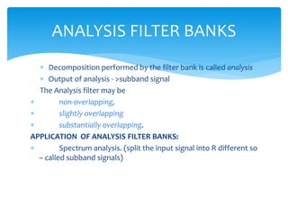


![DFT filter bank :
If the rth band filter hr[n] is computed from the
“modulation” of a single prototype filter h[n]
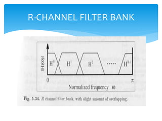
A DFT filter interpolation R = Number of bands K
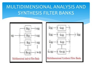
Applications Of Filter Banks
Sub-band Adaptive Filtering
Transmultiplexers
Graphic Equalizer
Signal Compression
Vocoder
UNIFORM DFT FILTER BANK](https://image.slidesharecdn.com/sanju-160412070249/85/FILTER-BANKS-13-320.jpg)
![ℎ 𝑟 𝑛 = ℎ 𝑛 𝑊𝑅
𝑟𝑛
= ℎ[𝑛]𝑒−𝑗2𝜋𝑟𝑛/𝑅
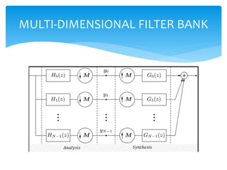
An efficient implementation of the R channel filter bank can be
generated using polyphasedecomposition of the filter ℎ 𝑟[𝑛]
and the input signal 𝑧[𝑛].
Because each of these bandpass filter is critically sampled, we
use a decomposition with R polyphase signals according to
ℎ 𝑛 =
𝑘=0
𝑅−1
ℎ 𝑘 𝑛 ↔ ℎ 𝑘 𝑚 = ℎ[𝑚𝑅 − 𝑘]
𝑥 𝑛 =
𝑘=0
𝑅−1
𝑥 𝑘 𝑛 ↔ 𝑥 𝑘 𝑚 = 𝑥[𝑚𝑅 − 𝑘]](https://image.slidesharecdn.com/sanju-160412070249/85/FILTER-BANKS-15-320.jpg)


![𝑓 𝑟
𝑛 =
1
𝑅
𝑓 𝑛 𝑊𝑅
𝑟𝑛
= 𝑓[𝑛]𝑒 𝑗2𝜋𝑟𝑛/𝑅
If we now combine the analysis and synthesis filter banks,
we can see that the DFT and IDFT annihilate each other, and
perfect reconstruction occurs if the convolution of the
included polyphase filter gives a unit sample function, i.e.,
ℎ 𝑟 𝑛 × 𝑓𝑟 𝑛 =
1
0
𝑛 = 𝑑
𝑒𝑙𝑠𝑒
In other words, the two polyphase functions must be
inverse filters of each other, i.e.,
𝐻𝑟 𝑧 × 𝐹𝑟 𝑧 = 𝑧−𝑑
𝐹𝑟 𝑧 =
𝑧−𝑑
𝐻𝑟(𝑧)
Where we allow a delay d in order to have casual
(realizable) filters. These ideal conditions cannot be met
exactly by two FIR filters.](https://image.slidesharecdn.com/sanju-160412070249/85/FILTER-BANKS-18-320.jpg)


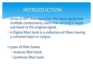
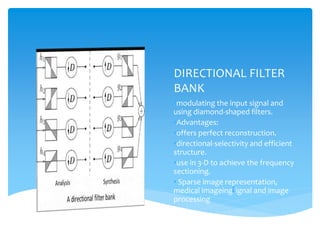
![ The construction rule is normally given by
ℎ 𝑛 = (−1) 𝑛 𝑔 𝑛 ⊶ 𝐻 𝑧 = 𝐺 −𝑧
For the synthesis use an expander (a sampling rate
increase of 2), and then two separate reconstruction
filters, 𝐺^ 𝑧 and 𝐻^ 𝑧 ,to reconstruct 𝑥[𝑛].
A perfectly reconstructed signal has the sample shape
as the original, up to a phase (time) shift.
CONTD…](https://image.slidesharecdn.com/sanju-160412070249/85/FILTER-BANKS-21-320.jpg)


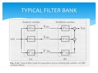
This document discusses filter banks, which are arrays of bandpass filters that separate an input signal into multiple sub-band components. It covers types of filter banks like analysis and synthesis banks, as well as uniform and non-uniform filter banks. Two-channel and polyphase two-channel filter banks are explained in more detail. Applications like signal compression and graphic equalizers are also mentioned. Lifting approaches for implementing filters efficiently are briefly outlined.