Downloaded 130 times
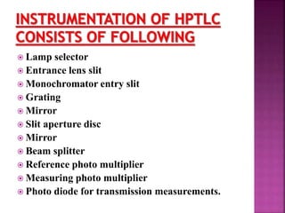

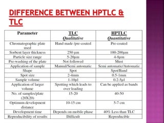
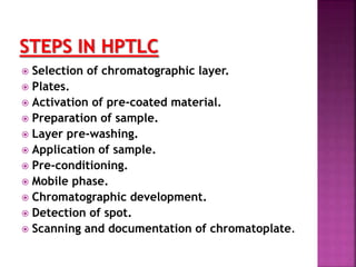
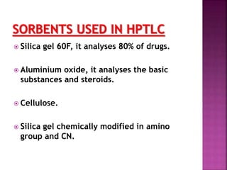


This document discusses high performance thin layer chromatography (HPTLC). It begins with an introduction and overview of HPTLC principles, instrumentation, differences from TLC, and application steps. The document then provides more details on the HPTLC instrumentation components, factors affecting separation, common stationary and mobile phases used, and application techniques. It concludes by discussing detection methods and some key applications of HPTLC in pharmaceuticals, food analysis, clinical studies, and forensics.


![high performance thin layer chromatography [HPTLC]](https://cdn.slidesharecdn.com/ss_thumbnails/54-191219130320-thumbnail.jpg?width=640&height=640&fit=bounds)


