DEPT OF ECE,ASE 2
Angle modulators
Angle modulation involves the generation of frequencies that were not present in the
input signal
The modulator or demodulator cannot be modelled as an LTI system
Angle modulators are generally time varying and nonlinear systems
There are two distinct methods for the generation of angle modulated signal
-direct method
-indirect method
3.
DEPT OF ECE,ASE 3
Direct method
Design an oscillator whose frequency changes with the input voltage-a voltage
- controlled oscillator
When the input voltage is zero, the oscillator generates a sinusoid of frequency fc
When the input voltage changes this frequency changes accordingly
There are two approaches to implement such a Voltage Controlled Oscillator, VCO
-using varactor diode
-using reactance tube
4.
DEPT OF ECE,ASE 4
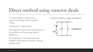
Direct method-using varactor diode
A varactor diode is a diode whose
capacitance changes with the applied
voltage
Also known as varicap diode
This capacitor is used in the tuned circuit of
the oscillator and the message signal is
applied to it
The frequency of the tuned circuit and
oscillator will change I accordance with the
message signal
Varactor diode in angle modulator
5.
DEPT OF ECE,ASE 5
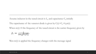
Assume inductor in the tuned circuit is L0 and capacitance C0 initially
The capacitance of the varactor diode is given by C(t)=C0+k0m(t)
When m(t)=0 the frequency of the tuned circuit is the carrier frequency given by
Wen m(t) is applied the frequency changes with the message signal
6.
DEPT OF ECE,ASE 6
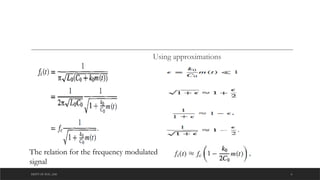
Using approximations
The relation for the frequency modulated
signal
7.
DEPT OF ECE,ASE 7
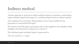
Indirect method
Another approach to generate an angle modulated signal is to generate a narrowband
angle modulated signal and change it to a wideband signal-known as indirect method
Any modulator for convention AM generation can be easily modified for the
generation of narrowband FM signal
The narrow band FM signal is generated, and it is then applied to the multiplier which
multiplies the instantaneous frequency by a factor 'n'
The wideband angle modulated signal is represented as
Y(t)=Ac cos(2πn fc t + nφ(t))
8.
DEPT OF ECE,ASE 8
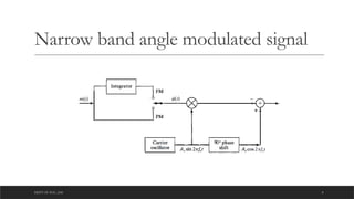
Narrow band angle modulated signal
DEPT OF ECE,ASE 10
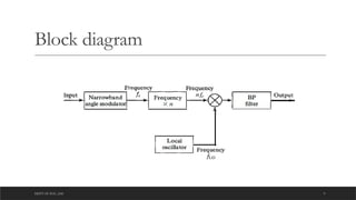
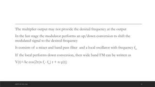
The multiplier output may not provide the desired frequency at the output
In the last stage the modulator performs an up/down conversion to shift the
modulated signal to the desired frequency
It consists of a mixer and band pass filter and a local oscillator with frequency flo
If the local performs down conversion, then wide band FM can be written as
Y(t)=Ac cos(2π(n fc- flo) t + n φ(t))
11.
DEPT OF ECE,ASE 11
FM demodulators
A variety of techniques and circuits have been developed for demodulating the FM
signals
• FM to AM conversion
•Phase shift discrimination
• Zero crossing detection
•Phase locked loop
12.
DEPT OF ECE,ASE 12
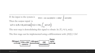
Angle demodulators
FM demodulators can be implemented using an AM demodulator to recover message signal
To transform FM signal into an AM signal it can be passed through an LTI system whose
frequency response is approximately a straight line in the frequency band of the FM signal
The frequency response of such a system is given as
|H(f)|=V0+k(f-fc) for |f-fc|< Bc/2
It yield an output proportional to the instantaneous frequency
The circuit coverts the frequency deviation into a corresponding amplitude change which is
proportional to m(t).
13.
DEPT OF ECE,ASE 13
If the input to the system is
Then the output signal is
The next step is demodulating this signal to obtain Ac (V0+k kf m(t)).
The first stage can be implemented using a differentiator with |H(f)|=2πf
14.
DEPT OF ECE,ASE 14
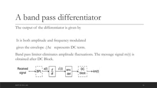
A band pass differentiator
The output of the differentiator is given by
It is both amplitude and frequency modulated
gives the envelope .(Ac represents DC term.
Band pass limiter eliminates amplitude fluctuations. The message signal m(t) is
obtained after DC Block.
15.
DEPT OF ECE,ASE 15
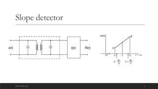
Tuned circuit demodulation(Slope
detection)
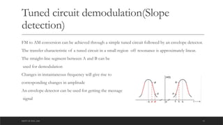
FM to AM conversion can be achieved through a simple tuned circuit followed by an envelope detector.
The transfer characteristic of a tuned circuit in a small region off resonance is approximately linear.
The straight-line segment between A and B can be
used for demodulation
Changes in instantaneous frequency will give rise to
corresponding changes in amplitude
An envelope detector can be used for getting the message
signal
DEPT OF ECE,ASE 17
Disadvantages with slope detector
Inefficient
Linear over only limited frequency range
Reacts to all amplitude changes
Difficult to adjust
The circuit can be easily implemented ,but the frequency characteristics may not be
wide enough
18.
DEPT OF ECE,ASE 18
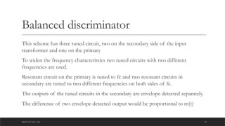
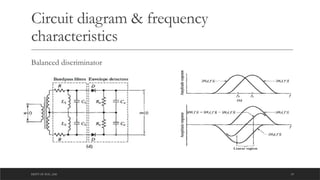
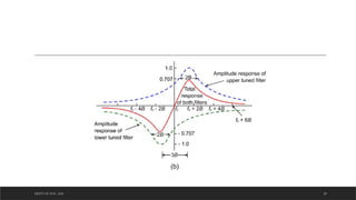
Balanced discriminator
This scheme has three tuned circuit, two on the secondary side of the input
transformer and one on the primary
To widen the frequency characteristics two tuned circuits with two different
frequencies are used.
Resonant circuit on the primary is tuned to fc and two resonant circuits in
secondary are tuned to two different frequencies on both sides of fc.
The outputs of the tuned circuits in the secondary are envelope detected separately.
The difference of two envelope detected output would be proportional to m(t)
19.
DEPT OF ECE,ASE 19
Circuit diagram & frequency
characteristics
Balanced discriminator
DEPT OF ECE,ASE 21
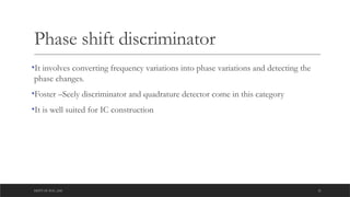
Phase shift discriminator
•It involves converting frequency variations into phase variations and detecting the
phase changes.
•Foster –Seely discriminator and quadrature detector come in this category
•It is well suited for IC construction
22.
DEPT OF ECE,ASE 22
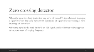
Zero crossing detector
When the input to a hard limiter is a sine wave of period T, it produces at its output
a square wave of the same period with transitions of square wave occurring at zero
crossings of sine wave
When the input to the hard limiter is an FM signal, the hard limiter output appears
as a square wave of varying frequency
DEPT OF ECE,ASE 24
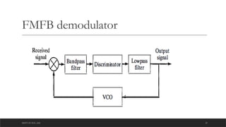
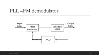
Phase locked loop
PLL is a versatile building block of present-day communication system
The basic aim of a PLL is to lock the instantaneous angle of a VCO output to the
instantaneous angle of a signal that is given as input to the PLL.
It consists of a phase comparator, loop filter and and VCO.
A properly designed negative feedback system ensures the error quantity is nearly
equal to zero
DEPT OF ECE,ASE 27
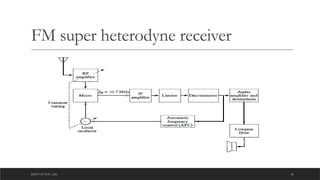
Commercial FM radio broadcasting utilizes the frequency band 88-108 MHz for the
transmission of voice and music signals. The carrier frequencies are separated by
200 kHz and the peak frequency deviation is fixed at 75 kHz. Preemphasis is
generally used.
The intermediate frequency is 10.7 MHz
28.
DEPT OF ECE,ASE 28
References
Fundamentals of communication systems-John G Proakis, Masoud M salehi
NPTEL