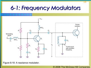
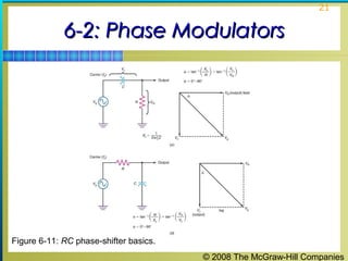
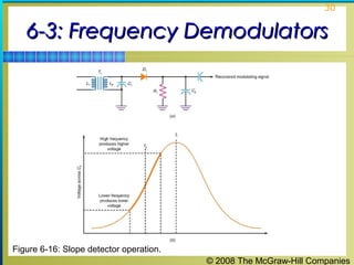
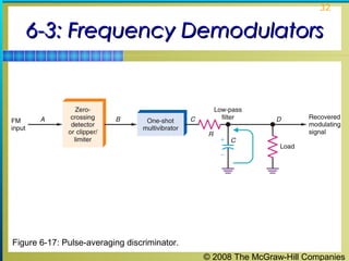
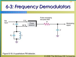
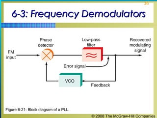
SlideShare a Scribd company logo
1 of 38
© 2008 The McGraw-Hill Companies
1
Principles of ElectronicPrinciples of Electronic
Communication SystemsCommunication Systems
Third Edition
Louis E. Frenzel, Jr.
© 2008 The McGraw-Hill Companies
2
Chapter 6Chapter 6
FM Circuits
© 2008 The McGraw-Hill Companies
3
Topics Covered in Chapter 6Topics Covered in Chapter 6
 6-1: Frequency Modulators
 6-2: Phase Modulators
 6-3: Frequency Demodulators
© 2008 The McGraw-Hill Companies
4
6-1: Frequency Modulators6-1: Frequency Modulators
 There are many circuits used to produce FM and PM
signals. There are two types of frequency modulator
circuits: direct circuits and phase modulation circuits.
 A frequency modulator is a circuit that varies carrier
frequency in accordance with the modulating signal.
 The carrier is generated by LC or crystal oscillator
circuits.
© 2008 The McGraw-Hill Companies
5
6-1: Frequency Modulators6-1: Frequency Modulators
 In LC oscillators, the carrier frequency can be
changed by varying either the inductance or
capacitance.
 The idea is to find a circuit or component that converts
a modulating voltage to a corresponding change in
capacitance or inductance.
 In crystal oscillators, the frequency is fixed by the
crystal.
 A varactor is a variable capacitance diode used to
change oscillator frequencies.
© 2008 The McGraw-Hill Companies
6
6-1: Frequency Modulators6-1: Frequency Modulators
Varactor Operation
 A junction diode is created when P- and N-type
semiconductors are formed during the manufacturing
process.
 A depletion region, where there are no free carriers,
holes, or electrons, is formed in the process.
 This region acts like a thin insulator that prevents
current from flowing through the device.
 A forward bias will cause the diode to conduct.
 A reverse bias will prevent current flow.
© 2008 The McGraw-Hill Companies
7
6-1: Frequency Modulators6-1: Frequency Modulators
Varactor Operation
 A reverse-biased diode acts like a small capacitor.
 The P- and N-type materials act as the two plates of the
capacitor.
 The depletion region acts as the dielectric material.
 The width of the depletion layer determines the width of
the dielectric and, therefore the amount of capacitance.
 All diodes exhibit variable capacitance.
 Varactors are designed to optimize this characteristic.
© 2008 The McGraw-Hill Companies
8
6-1: Frequency Modulators6-1: Frequency Modulators
Figure 6-2: Schematic symbols of a varactor diode.
© 2008 The McGraw-Hill Companies
9
6-1: Frequency Modulators6-1: Frequency Modulators
Figure 6-4: A direct-frequency-modulated carrier oscillator using a varactor diode.
© 2008 The McGraw-Hill Companies
10
6-1: Frequency Modulators6-1: Frequency Modulators
Varactor Modulator
 In Figure 6-4, the capacitance of varactor diode D1 and
L1 form the parallel tuned circuit of the oscillator.
 The value of C1 is made very large so its reactance is
very low.
 C1 connects the tuned circuit to the oscillator and blocks
the dc bias on the base of Q1 from being shorted to
ground through L1.
 The values of L1 and D1 fix the center carrier frequency.
 The modulating signal varies the effective voltage
applied to D1 and its capacitance varies.
© 2008 The McGraw-Hill Companies
11
6-1: Frequency Modulators6-1: Frequency Modulators
Varactor Modulator
 Most LC oscillators are not stable enough to provide a
carrier signal.
 The frequency of LC oscillators will vary with
temperature changes, variations in circuit voltage, and
other factors.
 As a result, crystal oscillators are normally used to set
carrier frequency.
© 2008 The McGraw-Hill Companies
12
6-1: Frequency Modulators6-1: Frequency Modulators
Frequency-Modulating a Crystal Oscillator
 Crystal oscillators provide highly accurate carrier
frequencies and their stability is superior to LC
oscillators.
 The frequency of a crystal oscillator can be varied by
changing the value of capacitance in series or parallel
with the crystal.
 By making the series capacitance a varactor diode,
frequency modulation can be achieved.
 The modulating signal is applied to the varactor diode
which changes the oscillator frequency.
© 2008 The McGraw-Hill Companies
13
6-1: Frequency Modulators6-1: Frequency Modulators
Figure 6-5: Frequency modulation of a crystal oscillator with a VVC.
© 2008 The McGraw-Hill Companies
14
6-1: Frequency Modulators6-1: Frequency Modulators
Frequency-Modulating a Crystal Oscillator
 Varactors are made with a wide range of capacitance
values, most units having a nominal capacitance in the
1- to 200-pF range.
 A frequency multiplier circuit is one whose output
frequency is some integer multiple of the input
frequency.
 A frequency multiplier that multiplies a frequency by two
is called a doubler.
 A frequency multiplier that multiplies a frequency by
three is called a tripler.
 Frequency multipliers can also be cascaded.
© 2008 The McGraw-Hill Companies
15
6-1: Frequency Modulators6-1: Frequency Modulators
Figure 6-6: How frequency multipliers increase carrier frequency and deviation.
© 2008 The McGraw-Hill Companies
16
6-1: Frequency Modulators6-1: Frequency Modulators
Voltage-Controlled Oscillators
 Oscillators whose frequencies are controlled by an
external input voltage are generally referred to as
voltage-controlled oscillators (VCOs).
 Voltage-controlled crystal oscillators are generally
referred to as VXOs.
 VCOs are primarily used in FM.
 VCOs are also used in voltage-to-frequency conversion
applications.
© 2008 The McGraw-Hill Companies
17
6-1: Frequency Modulators6-1: Frequency Modulators
Reactance Modulator
 A reactance modulator is a circuit that uses a
transistor amplifier that acts like either a variable
capacitor or an inductor.
 When the circuit is connected across the tuned circuit of
an oscillator, the oscillator frequency can be varied by
applying the modulating signal to the amplifier.
 Reactance modulators can produce frequency deviation
over a wide range.
 Reactance modulators are highly linear, so distortion is
minimal.
© 2008 The McGraw-Hill Companies
18
6-1: Frequency Modulators6-1: Frequency Modulators
Figure 6-10: A reactance modulator.
© 2008 The McGraw-Hill Companies
19
6-2: Phase Modulators6-2: Phase Modulators
 Most modern FM transmitters use some form of
phase modulation (PM) to produce indirect FM.
 In PM the carrier oscillator can be optimized for
frequency accuracy and stability.
 Crystal oscillators or crystal-controlled frequency
synthesizers can be used to set the carrier frequency
accurately and maintain stability.
 The output of the carrier oscillator is fed to a phase
modulator where the phase shift is made to vary in
accordance with the modulating signal.
© 2008 The McGraw-Hill Companies
20
6-2: Phase Modulators6-2: Phase Modulators
 Simple phase shifters do not produce a linear
response over a large range of phase shift.
 To compensate for this, restrict the total allowable
phase shift to maximize linearity.
 Multipliers must also be used to achieve the desired
deviation.
© 2008 The McGraw-Hill Companies
21
6-2: Phase Modulators6-2: Phase Modulators
Figure 6-11: RC phase-shifter basics.
© 2008 The McGraw-Hill Companies
22
6-2: Phase Modulators6-2: Phase Modulators
Varactor Phase Modulators
 A simple phase-shift circuit can be used as a phase
modulator if the resistance or capacitance can be made
to vary with the modulating signal.
 A varactor can be used to vary capacitance and achieve
phase shift modulation.
© 2008 The McGraw-Hill Companies
23
6-2: Phase Modulators6-2: Phase Modulators
Figure 6-12: A varactor phase modulator.
© 2008 The McGraw-Hill Companies
24
6-2: Phase Modulators6-2: Phase Modulators
Transistor Phase Modulator
 A transistor can be used as a variable resistor to create
a phase modulator.
 A standard common emitter class A amplifier biased
into the linear region is used in PM.
 The transistor from collector to ground acts like a
resistor.
 The transistor’s resistance forms part of the phase
shifting circuit.
© 2008 The McGraw-Hill Companies
25
6-2: Phase Modulators6-2: Phase Modulators
Figure 6-13: A transistor phase shifter.
© 2008 The McGraw-Hill Companies
26
6-2: Phase Modulators6-2: Phase Modulators
Tuned-Circuit Phase Modulators
 Most phase modulators are capable of producing a
small amount of phase shift. The limited phase shift,
therefore, produces a limited frequency shift.
 Phase and frequency shift can be increased by using a
parallel tuned circuit.
 At resonance, a parallel resonant circuit acts like a large
resistor.
 Off resonance, the circuit acts inductively or capacitively
and produces a phase shift.
© 2008 The McGraw-Hill Companies
27
6-2: Phase Modulators6-2: Phase Modulators
Tuned-Circuit Phase Modulators
 Phase modulators are easy to implement, but they
have two main disadvantages.
1. The amount of phase shift they produce and the
resulting frequency deviation are relatively low.
2. All the phase-shift circuits produce amplitude
variations as well as phase changes.
© 2008 The McGraw-Hill Companies
28
6-3: Frequency Demodulators6-3: Frequency Demodulators
 Any circuit that will convert a frequency variation in the
carrier back into a proportional voltage variation can
be used to demodulate or detect FM signals.
 Circuits used to recover the original modulating signal
from an FM transmission are called:
 Demodulators
 Detectors
 Discriminators
© 2008 The McGraw-Hill Companies
29
6-3: Frequency Demodulators6-3: Frequency Demodulators
Slope Detector
 The slope detector makes use of a tuned circuit and a
diode detector to convert frequency variations into
voltage variations.
 The main difficulty with slope detectors lies in tuning
them.
© 2008 The McGraw-Hill Companies
30
6-3: Frequency Demodulators6-3: Frequency Demodulators
Figure 6-16: Slope detector operation.
© 2008 The McGraw-Hill Companies
31
6-3: Frequency Demodulators6-3: Frequency Demodulators
Pulse-Averaging Discriminators
 A pulse-averaging discriminator uses a zero crossing
detector, a one shot multivibrator and a low-pass filter in
order to recover the original modulating signal.
 The pulse-averaging discriminator is a very high-quality
frequency demodulator.
 Originally this discriminator was limited to expensive
telemetry and industrial control applications.
 With availability of low-cost ICs, this discriminator is
used in many electronic products.
© 2008 The McGraw-Hill Companies
32
6-3: Frequency Demodulators6-3: Frequency Demodulators
Figure 6-17: Pulse-averaging discriminator.
© 2008 The McGraw-Hill Companies
33
6-3: Frequency Demodulators6-3: Frequency Demodulators
Quadrature Detector
 The quadrature detector is probably the single most
widely used FM demodulator.
 The quadrature detector is primarily used in TV
demodulation.
 This detector is used in some FM radio stations.
 The quadrature detector uses a phase-shift circuit to
produce a phase shift of 90 degrees at the unmodulated
carrier frequency.
© 2008 The McGraw-Hill Companies
34
6-3: Frequency Demodulators6-3: Frequency Demodulators
Figure 6-19: A quadrature FM detector.
© 2008 The McGraw-Hill Companies
35
6-3: Frequency Demodulators6-3: Frequency Demodulators
Phase-Locked Loops
 A phase-locked loop (PLL) is a frequency- or phase-
sensitive feedback control circuit used in frequency
demodulation, frequency synthesizers, and various
filtering and signal-detection applications. PLLs have
three basic elements. They are:
 Phase detector
 Low-pass filter
 Voltage-controlled oscillator
© 2008 The McGraw-Hill Companies
36
6-3: Frequency Demodulators6-3: Frequency Demodulators
Figure 6-21: Block diagram of a PLL.
© 2008 The McGraw-Hill Companies
37
6-3: Frequency Demodulators6-3: Frequency Demodulators
Phase-Locked Loops
 The primary job of the phase detector is to compare the
two input signals and generate an output signal that,
when filtered, will control the VCO.
 If there is a phase or frequency difference between the
FM input and VCO signals, the phase detector output
varies in proportion to the difference.
 The filtered output adjusts the VCO frequency in an
attempt to correct for the original frequency or phase
difference.
© 2008 The McGraw-Hill Companies
38
6-3: Frequency Demodulators6-3: Frequency Demodulators
Phase-Locked Loops
 This dc control voltage, called the error signal, is also
the feedback in this circuit.
 When no input signal is applied, the phase detector and
low-pass filter outputs are zero.
 The VCO then operates at what is called the free-
running frequency, its normal operating frequency as
determined by internal frequency-determining
components.

More Related Content

What's hot

Chapter07 digital comm tech
Chapter07 digital comm techChapter07 digital comm tech
Chapter07 digital comm techSikander Ghunio
 
Principles of electronic communication systems 4th edition frenzel solutions ...
Principles of electronic communication systems 4th edition frenzel solutions ...Principles of electronic communication systems 4th edition frenzel solutions ...
Principles of electronic communication systems 4th edition frenzel solutions ...issac32342
 
Chapter08 radio transmitters
Chapter08 radio transmittersChapter08 radio transmitters
Chapter08 radio transmittersSikander Ghunio
 
Power control in power systems
Power control in power systemsPower control in power systems
Power control in power systemsAbhinash Yadav
 
Low frequency ac transmission for power systems by Aamir Saleem
Low frequency ac transmission for power systems by Aamir SaleemLow frequency ac transmission for power systems by Aamir Saleem
Low frequency ac transmission for power systems by Aamir SaleemAamir Saleem
 
power line carrier communication
power line carrier communicationpower line carrier communication
power line carrier communicationLAVANYA d
 
Fm Transmitter and receiver
 Fm Transmitter and receiver Fm Transmitter and receiver
Fm Transmitter and receivernurnaser1234
 
Power line carrier communication
Power line carrier communicationPower line carrier communication
Power line carrier communicationuttarakhatik
 
Power line carrier communication
Power line carrier communicationPower line carrier communication
Power line carrier communicationKAMAL SOLANKI
 
Plcc and satelite communcation
Plcc and satelite communcation Plcc and satelite communcation
Plcc and satelite communcation ashutoshgupta1102
 
Introduction to communication system lecture2
Introduction to communication system lecture2Introduction to communication system lecture2
Introduction to communication system lecture2Jumaan Ally Mohamed
 

What's hot (16)

Chapter07 digital comm tech
Chapter07 digital comm techChapter07 digital comm tech
Chapter07 digital comm tech
 
Principles of electronic communication systems 4th edition frenzel solutions ...
Principles of electronic communication systems 4th edition frenzel solutions ...Principles of electronic communication systems 4th edition frenzel solutions ...
Principles of electronic communication systems 4th edition frenzel solutions ...
 
3rd qrtr +++
3rd qrtr +++3rd qrtr +++
3rd qrtr +++
 
Ref ch01 louis-frenzel
Ref ch01 louis-frenzelRef ch01 louis-frenzel
Ref ch01 louis-frenzel
 
Chapter08 radio transmitters
Chapter08 radio transmittersChapter08 radio transmitters
Chapter08 radio transmitters
 
analog communication
analog communicationanalog communication
analog communication
 
Power control in power systems
Power control in power systemsPower control in power systems
Power control in power systems
 
Low frequency ac transmission for power systems by Aamir Saleem
Low frequency ac transmission for power systems by Aamir SaleemLow frequency ac transmission for power systems by Aamir Saleem
Low frequency ac transmission for power systems by Aamir Saleem
 
power line carrier communication
power line carrier communicationpower line carrier communication
power line carrier communication
 
Power Line Carrier Communication PLCC
Power Line Carrier Communication PLCCPower Line Carrier Communication PLCC
Power Line Carrier Communication PLCC
 
Fm Transmitter and receiver
 Fm Transmitter and receiver Fm Transmitter and receiver
Fm Transmitter and receiver
 
MODULATION
MODULATIONMODULATION
MODULATION
 
Power line carrier communication
Power line carrier communicationPower line carrier communication
Power line carrier communication
 
Power line carrier communication
Power line carrier communicationPower line carrier communication
Power line carrier communication
 
Plcc and satelite communcation
Plcc and satelite communcation Plcc and satelite communcation
Plcc and satelite communcation
 
Introduction to communication system lecture2
Introduction to communication system lecture2Introduction to communication system lecture2
Introduction to communication system lecture2
 

Similar to Chapter06

WEEK-10-AM-MODULATOR-DEMODULATOR.pdf
WEEK-10-AM-MODULATOR-DEMODULATOR.pdfWEEK-10-AM-MODULATOR-DEMODULATOR.pdf
WEEK-10-AM-MODULATOR-DEMODULATOR.pdfRyanJhesTolentino1
 
Design of High-Speed Dynamic Double-Tail Comparator
Design of High-Speed Dynamic Double-Tail ComparatorDesign of High-Speed Dynamic Double-Tail Comparator
Design of High-Speed Dynamic Double-Tail ComparatorIJERDJOURNAL
 
Simulation of H6 full bridge Inverter for grid connected PV system using SPWM...
Simulation of H6 full bridge Inverter for grid connected PV system using SPWM...Simulation of H6 full bridge Inverter for grid connected PV system using SPWM...
Simulation of H6 full bridge Inverter for grid connected PV system using SPWM...IRJET Journal
 
IRJET- Power Quality Improvement by Harmonic Reduction using Compact Desi...
IRJET-  	  Power Quality Improvement by Harmonic Reduction using Compact Desi...IRJET-  	  Power Quality Improvement by Harmonic Reduction using Compact Desi...
IRJET- Power Quality Improvement by Harmonic Reduction using Compact Desi...IRJET Journal
 
IRJET- Wireless Power Theft Monitoring System using Zigbee
IRJET- Wireless Power Theft Monitoring System using ZigbeeIRJET- Wireless Power Theft Monitoring System using Zigbee
IRJET- Wireless Power Theft Monitoring System using ZigbeeIRJET Journal
 
IRJET - Comparison of Different Third Harmonic Injected PWM Strategies for 5-...
IRJET - Comparison of Different Third Harmonic Injected PWM Strategies for 5-...IRJET - Comparison of Different Third Harmonic Injected PWM Strategies for 5-...
IRJET - Comparison of Different Third Harmonic Injected PWM Strategies for 5-...IRJET Journal
 
An operational amplifier with recycling folded cascode topology and adaptive ...
An operational amplifier with recycling folded cascode topology and adaptive ...An operational amplifier with recycling folded cascode topology and adaptive ...
An operational amplifier with recycling folded cascode topology and adaptive ...VLSICS Design
 
DYNAMICS OF AN OSCILLATOR FOR SINUSOIDAL INPUT
DYNAMICS OF AN OSCILLATOR FOR SINUSOIDAL INPUTDYNAMICS OF AN OSCILLATOR FOR SINUSOIDAL INPUT
DYNAMICS OF AN OSCILLATOR FOR SINUSOIDAL INPUTIRJET Journal
 
Design and Implementation of a Microcontroller Based DC/AC Inverter
Design and Implementation of a Microcontroller Based DC/AC InverterDesign and Implementation of a Microcontroller Based DC/AC Inverter
Design and Implementation of a Microcontroller Based DC/AC InverterFiras Mohammed Ali Al-Raie
 
High Voltage Direct Current Transmission Systems 2Mark Materials
High Voltage Direct Current Transmission Systems 2Mark MaterialsHigh Voltage Direct Current Transmission Systems 2Mark Materials
High Voltage Direct Current Transmission Systems 2Mark MaterialsSanthosh Kumar
 
Power Quality Analysis Using Active NPC Multilevel inverter in PV sourced sta...
Power Quality Analysis Using Active NPC Multilevel inverter in PV sourced sta...Power Quality Analysis Using Active NPC Multilevel inverter in PV sourced sta...
Power Quality Analysis Using Active NPC Multilevel inverter in PV sourced sta...IRJET Journal
 

Similar to Chapter06 (20)

Chapter08
Chapter08Chapter08
Chapter08
 
Chapter04
Chapter04Chapter04
Chapter04
 
Modulators
ModulatorsModulators
Modulators
 
WEEK-10-AM-MODULATOR-DEMODULATOR.pdf
WEEK-10-AM-MODULATOR-DEMODULATOR.pdfWEEK-10-AM-MODULATOR-DEMODULATOR.pdf
WEEK-10-AM-MODULATOR-DEMODULATOR.pdf
 
Design of High-Speed Dynamic Double-Tail Comparator
Design of High-Speed Dynamic Double-Tail ComparatorDesign of High-Speed Dynamic Double-Tail Comparator
Design of High-Speed Dynamic Double-Tail Comparator
 
Simulation of H6 full bridge Inverter for grid connected PV system using SPWM...
Simulation of H6 full bridge Inverter for grid connected PV system using SPWM...Simulation of H6 full bridge Inverter for grid connected PV system using SPWM...
Simulation of H6 full bridge Inverter for grid connected PV system using SPWM...
 
Overview of Soft-Switching DC-DC Converters
Overview of Soft-Switching DC-DC ConvertersOverview of Soft-Switching DC-DC Converters
Overview of Soft-Switching DC-DC Converters
 
24 547-558
24 547-55824 547-558
24 547-558
 
IRJET- Power Quality Improvement by Harmonic Reduction using Compact Desi...
IRJET-  	  Power Quality Improvement by Harmonic Reduction using Compact Desi...IRJET-  	  Power Quality Improvement by Harmonic Reduction using Compact Desi...
IRJET- Power Quality Improvement by Harmonic Reduction using Compact Desi...
 
[IJET V2I5P12] Authors: Mr. Harikrishnan U, Dr. Bos Mathew Jos, Mr.Thomas P R...
[IJET V2I5P12] Authors: Mr. Harikrishnan U, Dr. Bos Mathew Jos, Mr.Thomas P R...[IJET V2I5P12] Authors: Mr. Harikrishnan U, Dr. Bos Mathew Jos, Mr.Thomas P R...
[IJET V2I5P12] Authors: Mr. Harikrishnan U, Dr. Bos Mathew Jos, Mr.Thomas P R...
 
IRJET- Wireless Power Theft Monitoring System using Zigbee
IRJET- Wireless Power Theft Monitoring System using ZigbeeIRJET- Wireless Power Theft Monitoring System using Zigbee
IRJET- Wireless Power Theft Monitoring System using Zigbee
 
IRJET - Comparison of Different Third Harmonic Injected PWM Strategies for 5-...
IRJET - Comparison of Different Third Harmonic Injected PWM Strategies for 5-...IRJET - Comparison of Different Third Harmonic Injected PWM Strategies for 5-...
IRJET - Comparison of Different Third Harmonic Injected PWM Strategies for 5-...
 
Solid-State Transformer (S2T) of Single Phase Matrix Converter
Solid-State Transformer (S2T) of Single Phase Matrix ConverterSolid-State Transformer (S2T) of Single Phase Matrix Converter
Solid-State Transformer (S2T) of Single Phase Matrix Converter
 
Multilevel Inverter
Multilevel InverterMultilevel Inverter
Multilevel Inverter
 
An operational amplifier with recycling folded cascode topology and adaptive ...
An operational amplifier with recycling folded cascode topology and adaptive ...An operational amplifier with recycling folded cascode topology and adaptive ...
An operational amplifier with recycling folded cascode topology and adaptive ...
 
DYNAMICS OF AN OSCILLATOR FOR SINUSOIDAL INPUT
DYNAMICS OF AN OSCILLATOR FOR SINUSOIDAL INPUTDYNAMICS OF AN OSCILLATOR FOR SINUSOIDAL INPUT
DYNAMICS OF AN OSCILLATOR FOR SINUSOIDAL INPUT
 
Design and Implementation of a Microcontroller Based DC/AC Inverter
Design and Implementation of a Microcontroller Based DC/AC InverterDesign and Implementation of a Microcontroller Based DC/AC Inverter
Design and Implementation of a Microcontroller Based DC/AC Inverter
 
High Voltage Direct Current Transmission Systems 2Mark Materials
High Voltage Direct Current Transmission Systems 2Mark MaterialsHigh Voltage Direct Current Transmission Systems 2Mark Materials
High Voltage Direct Current Transmission Systems 2Mark Materials
 
Power Quality Analysis Using Active NPC Multilevel inverter in PV sourced sta...
Power Quality Analysis Using Active NPC Multilevel inverter in PV sourced sta...Power Quality Analysis Using Active NPC Multilevel inverter in PV sourced sta...
Power Quality Analysis Using Active NPC Multilevel inverter in PV sourced sta...
 
Power Quality Analysis Using Active NPC Multilevel inverter in PV sourced sta...
Power Quality Analysis Using Active NPC Multilevel inverter in PV sourced sta...Power Quality Analysis Using Active NPC Multilevel inverter in PV sourced sta...
Power Quality Analysis Using Active NPC Multilevel inverter in PV sourced sta...
 

More from bhagavanprasad (20)

Chapter03
Chapter03Chapter03
Chapter03
 
Chapter02
Chapter02Chapter02
Chapter02
 
Chapter01
Chapter01Chapter01
Chapter01
 
Chapter07
Chapter07Chapter07
Chapter07
 
Chapter05
Chapter05 Chapter05
Chapter05
 
Ch10 2 v1
Ch10 2 v1Ch10 2 v1
Ch10 2 v1
 
Ch10 1 v1
Ch10 1 v1Ch10 1 v1
Ch10 1 v1
 
Ch7 1 v1
Ch7 1 v1Ch7 1 v1
Ch7 1 v1
 
Ch6 2 v1
Ch6 2 v1Ch6 2 v1
Ch6 2 v1
 
Ch6 1 v1
Ch6 1 v1Ch6 1 v1
Ch6 1 v1
 
Ch5 2 v1
Ch5 2 v1Ch5 2 v1
Ch5 2 v1
 
Ch5 1 v1
Ch5 1 v1Ch5 1 v1
Ch5 1 v1
 
Ch4 2 v1
Ch4 2 v1Ch4 2 v1
Ch4 2 v1
 
Ch4 1 v1
Ch4 1 v1Ch4 1 v1
Ch4 1 v1
 
Ch3 5 v1
Ch3 5 v1Ch3 5 v1
Ch3 5 v1
 
Ch3 4 v1
Ch3 4 v1Ch3 4 v1
Ch3 4 v1
 
Ch3 3 v1
Ch3 3 v1Ch3 3 v1
Ch3 3 v1
 
Ch3 2 v1
Ch3 2 v1Ch3 2 v1
Ch3 2 v1
 
Ch3 1 v1
Ch3 1 v1Ch3 1 v1
Ch3 1 v1
 
Ch2 v1
Ch2 v1Ch2 v1
Ch2 v1
 

Recently uploaded

What are the advantages and disadvantages of membrane structures.pptx
What are the advantages and disadvantages of membrane structures.pptxWhat are the advantages and disadvantages of membrane structures.pptx
What are the advantages and disadvantages of membrane structures.pptxwendy cai
 
Work Experience-Dalton Park.pptxfvvvvvvv
Work Experience-Dalton Park.pptxfvvvvvvvWork Experience-Dalton Park.pptxfvvvvvvv
Work Experience-Dalton Park.pptxfvvvvvvvLewisJB
 
Call Us ≽ 8377877756 ≼ Call Girls In Shastri Nagar (Delhi)
Call Us ≽ 8377877756 ≼ Call Girls In Shastri Nagar (Delhi)Call Us ≽ 8377877756 ≼ Call Girls In Shastri Nagar (Delhi)
Call Us ≽ 8377877756 ≼ Call Girls In Shastri Nagar (Delhi)dollysharma2066
 
An experimental study in using natural admixture as an alternative for chemic...
An experimental study in using natural admixture as an alternative for chemic...An experimental study in using natural admixture as an alternative for chemic...
An experimental study in using natural admixture as an alternative for chemic...Chandu841456
 
Sachpazis Costas: Geotechnical Engineering: A student's Perspective Introduction
Sachpazis Costas: Geotechnical Engineering: A student's Perspective IntroductionSachpazis Costas: Geotechnical Engineering: A student's Perspective Introduction
Sachpazis Costas: Geotechnical Engineering: A student's Perspective IntroductionDr.Costas Sachpazis
 
Decoding Kotlin - Your guide to solving the mysterious in Kotlin.pptx
Decoding Kotlin - Your guide to solving the mysterious in Kotlin.pptxDecoding Kotlin - Your guide to solving the mysterious in Kotlin.pptx
Decoding Kotlin - Your guide to solving the mysterious in Kotlin.pptxJoão Esperancinha
 
CCS355 Neural Network & Deep Learning Unit II Notes with Question bank .pdf
CCS355 Neural Network & Deep Learning Unit II Notes with Question bank .pdfCCS355 Neural Network & Deep Learning Unit II Notes with Question bank .pdf
CCS355 Neural Network & Deep Learning Unit II Notes with Question bank .pdfAsst.prof M.Gokilavani
 
HARMONY IN THE NATURE AND EXISTENCE - Unit-IV
HARMONY IN THE NATURE AND EXISTENCE - Unit-IVHARMONY IN THE NATURE AND EXISTENCE - Unit-IV
HARMONY IN THE NATURE AND EXISTENCE - Unit-IVRajaP95
 
INFLUENCE OF NANOSILICA ON THE PROPERTIES OF CONCRETE
INFLUENCE OF NANOSILICA ON THE PROPERTIES OF CONCRETEINFLUENCE OF NANOSILICA ON THE PROPERTIES OF CONCRETE
INFLUENCE OF NANOSILICA ON THE PROPERTIES OF CONCRETEroselinkalist12
 
Call Girls Narol 7397865700 Independent Call Girls
Call Girls Narol 7397865700 Independent Call GirlsCall Girls Narol 7397865700 Independent Call Girls
Call Girls Narol 7397865700 Independent Call Girlsssuser7cb4ff
 
Concrete Mix Design - IS 10262-2019 - .pptx
Concrete Mix Design - IS 10262-2019 - .pptxConcrete Mix Design - IS 10262-2019 - .pptx
Concrete Mix Design - IS 10262-2019 - .pptxKartikeyaDwivedi3
 
Electronically Controlled suspensions system .pdf
Electronically Controlled suspensions system .pdfElectronically Controlled suspensions system .pdf
Electronically Controlled suspensions system .pdfme23b1001
 
Application of Residue Theorem to evaluate real integrations.pptx
Application of Residue Theorem to evaluate real integrations.pptxApplication of Residue Theorem to evaluate real integrations.pptx
Application of Residue Theorem to evaluate real integrations.pptx959SahilShah
 
CCS355 Neural Network & Deep Learning UNIT III notes and Question bank .pdf
CCS355 Neural Network & Deep Learning UNIT III notes and Question bank .pdfCCS355 Neural Network & Deep Learning UNIT III notes and Question bank .pdf
CCS355 Neural Network & Deep Learning UNIT III notes and Question bank .pdfAsst.prof M.Gokilavani
 
Risk Assessment For Installation of Drainage Pipes.pdf
Risk Assessment For Installation of Drainage Pipes.pdfRisk Assessment For Installation of Drainage Pipes.pdf
Risk Assessment For Installation of Drainage Pipes.pdfROCENODodongVILLACER
 
DATA ANALYTICS PPT definition usage example
DATA ANALYTICS PPT definition usage exampleDATA ANALYTICS PPT definition usage example
DATA ANALYTICS PPT definition usage examplePragyanshuParadkar1
 

Recently uploaded (20)

What are the advantages and disadvantages of membrane structures.pptx
What are the advantages and disadvantages of membrane structures.pptxWhat are the advantages and disadvantages of membrane structures.pptx
What are the advantages and disadvantages of membrane structures.pptx
 
Work Experience-Dalton Park.pptxfvvvvvvv
Work Experience-Dalton Park.pptxfvvvvvvvWork Experience-Dalton Park.pptxfvvvvvvv
Work Experience-Dalton Park.pptxfvvvvvvv
 
Call Us ≽ 8377877756 ≼ Call Girls In Shastri Nagar (Delhi)
Call Us ≽ 8377877756 ≼ Call Girls In Shastri Nagar (Delhi)Call Us ≽ 8377877756 ≼ Call Girls In Shastri Nagar (Delhi)
Call Us ≽ 8377877756 ≼ Call Girls In Shastri Nagar (Delhi)
 
9953056974 Call Girls In South Ex, Escorts (Delhi) NCR.pdf
9953056974 Call Girls In South Ex, Escorts (Delhi) NCR.pdf9953056974 Call Girls In South Ex, Escorts (Delhi) NCR.pdf
9953056974 Call Girls In South Ex, Escorts (Delhi) NCR.pdf
 
An experimental study in using natural admixture as an alternative for chemic...
An experimental study in using natural admixture as an alternative for chemic...An experimental study in using natural admixture as an alternative for chemic...
An experimental study in using natural admixture as an alternative for chemic...
 
Sachpazis Costas: Geotechnical Engineering: A student's Perspective Introduction
Sachpazis Costas: Geotechnical Engineering: A student's Perspective IntroductionSachpazis Costas: Geotechnical Engineering: A student's Perspective Introduction
Sachpazis Costas: Geotechnical Engineering: A student's Perspective Introduction
 
Decoding Kotlin - Your guide to solving the mysterious in Kotlin.pptx
Decoding Kotlin - Your guide to solving the mysterious in Kotlin.pptxDecoding Kotlin - Your guide to solving the mysterious in Kotlin.pptx
Decoding Kotlin - Your guide to solving the mysterious in Kotlin.pptx
 
🔝9953056974🔝!!-YOUNG call girls in Rajendra Nagar Escort rvice Shot 2000 nigh...
🔝9953056974🔝!!-YOUNG call girls in Rajendra Nagar Escort rvice Shot 2000 nigh...🔝9953056974🔝!!-YOUNG call girls in Rajendra Nagar Escort rvice Shot 2000 nigh...
🔝9953056974🔝!!-YOUNG call girls in Rajendra Nagar Escort rvice Shot 2000 nigh...
 
CCS355 Neural Network & Deep Learning Unit II Notes with Question bank .pdf
CCS355 Neural Network & Deep Learning Unit II Notes with Question bank .pdfCCS355 Neural Network & Deep Learning Unit II Notes with Question bank .pdf
CCS355 Neural Network & Deep Learning Unit II Notes with Question bank .pdf
 
HARMONY IN THE NATURE AND EXISTENCE - Unit-IV
HARMONY IN THE NATURE AND EXISTENCE - Unit-IVHARMONY IN THE NATURE AND EXISTENCE - Unit-IV
HARMONY IN THE NATURE AND EXISTENCE - Unit-IV
 
INFLUENCE OF NANOSILICA ON THE PROPERTIES OF CONCRETE
INFLUENCE OF NANOSILICA ON THE PROPERTIES OF CONCRETEINFLUENCE OF NANOSILICA ON THE PROPERTIES OF CONCRETE
INFLUENCE OF NANOSILICA ON THE PROPERTIES OF CONCRETE
 
Call Girls Narol 7397865700 Independent Call Girls
Call Girls Narol 7397865700 Independent Call GirlsCall Girls Narol 7397865700 Independent Call Girls
Call Girls Narol 7397865700 Independent Call Girls
 
Concrete Mix Design - IS 10262-2019 - .pptx
Concrete Mix Design - IS 10262-2019 - .pptxConcrete Mix Design - IS 10262-2019 - .pptx
Concrete Mix Design - IS 10262-2019 - .pptx
 
Electronically Controlled suspensions system .pdf
Electronically Controlled suspensions system .pdfElectronically Controlled suspensions system .pdf
Electronically Controlled suspensions system .pdf
 
Application of Residue Theorem to evaluate real integrations.pptx
Application of Residue Theorem to evaluate real integrations.pptxApplication of Residue Theorem to evaluate real integrations.pptx
Application of Residue Theorem to evaluate real integrations.pptx
 
POWER SYSTEMS-1 Complete notes examples
POWER SYSTEMS-1 Complete notes  examplesPOWER SYSTEMS-1 Complete notes  examples
POWER SYSTEMS-1 Complete notes examples
 
CCS355 Neural Network & Deep Learning UNIT III notes and Question bank .pdf
CCS355 Neural Network & Deep Learning UNIT III notes and Question bank .pdfCCS355 Neural Network & Deep Learning UNIT III notes and Question bank .pdf
CCS355 Neural Network & Deep Learning UNIT III notes and Question bank .pdf
 
Risk Assessment For Installation of Drainage Pipes.pdf
Risk Assessment For Installation of Drainage Pipes.pdfRisk Assessment For Installation of Drainage Pipes.pdf
Risk Assessment For Installation of Drainage Pipes.pdf
 
DATA ANALYTICS PPT definition usage example
DATA ANALYTICS PPT definition usage exampleDATA ANALYTICS PPT definition usage example
DATA ANALYTICS PPT definition usage example
 
young call girls in Rajiv Chowk🔝 9953056974 🔝 Delhi escort Service
young call girls in Rajiv Chowk🔝 9953056974 🔝 Delhi escort Serviceyoung call girls in Rajiv Chowk🔝 9953056974 🔝 Delhi escort Service
young call girls in Rajiv Chowk🔝 9953056974 🔝 Delhi escort Service
 

Chapter06

  • 1. © 2008 The McGraw-Hill Companies 1 Principles of ElectronicPrinciples of Electronic Communication SystemsCommunication Systems Third Edition Louis E. Frenzel, Jr.
  • 2. © 2008 The McGraw-Hill Companies 2 Chapter 6Chapter 6 FM Circuits
  • 3. © 2008 The McGraw-Hill Companies 3 Topics Covered in Chapter 6Topics Covered in Chapter 6  6-1: Frequency Modulators  6-2: Phase Modulators  6-3: Frequency Demodulators
  • 4. © 2008 The McGraw-Hill Companies 4 6-1: Frequency Modulators6-1: Frequency Modulators  There are many circuits used to produce FM and PM signals. There are two types of frequency modulator circuits: direct circuits and phase modulation circuits.  A frequency modulator is a circuit that varies carrier frequency in accordance with the modulating signal.  The carrier is generated by LC or crystal oscillator circuits.
  • 5. © 2008 The McGraw-Hill Companies 5 6-1: Frequency Modulators6-1: Frequency Modulators  In LC oscillators, the carrier frequency can be changed by varying either the inductance or capacitance.  The idea is to find a circuit or component that converts a modulating voltage to a corresponding change in capacitance or inductance.  In crystal oscillators, the frequency is fixed by the crystal.  A varactor is a variable capacitance diode used to change oscillator frequencies.
  • 6. © 2008 The McGraw-Hill Companies 6 6-1: Frequency Modulators6-1: Frequency Modulators Varactor Operation  A junction diode is created when P- and N-type semiconductors are formed during the manufacturing process.  A depletion region, where there are no free carriers, holes, or electrons, is formed in the process.  This region acts like a thin insulator that prevents current from flowing through the device.  A forward bias will cause the diode to conduct.  A reverse bias will prevent current flow.
  • 7. © 2008 The McGraw-Hill Companies 7 6-1: Frequency Modulators6-1: Frequency Modulators Varactor Operation  A reverse-biased diode acts like a small capacitor.  The P- and N-type materials act as the two plates of the capacitor.  The depletion region acts as the dielectric material.  The width of the depletion layer determines the width of the dielectric and, therefore the amount of capacitance.  All diodes exhibit variable capacitance.  Varactors are designed to optimize this characteristic.
  • 8. © 2008 The McGraw-Hill Companies 8 6-1: Frequency Modulators6-1: Frequency Modulators Figure 6-2: Schematic symbols of a varactor diode.
  • 9. © 2008 The McGraw-Hill Companies 9 6-1: Frequency Modulators6-1: Frequency Modulators Figure 6-4: A direct-frequency-modulated carrier oscillator using a varactor diode.
  • 10. © 2008 The McGraw-Hill Companies 10 6-1: Frequency Modulators6-1: Frequency Modulators Varactor Modulator  In Figure 6-4, the capacitance of varactor diode D1 and L1 form the parallel tuned circuit of the oscillator.  The value of C1 is made very large so its reactance is very low.  C1 connects the tuned circuit to the oscillator and blocks the dc bias on the base of Q1 from being shorted to ground through L1.  The values of L1 and D1 fix the center carrier frequency.  The modulating signal varies the effective voltage applied to D1 and its capacitance varies.
  • 11. © 2008 The McGraw-Hill Companies 11 6-1: Frequency Modulators6-1: Frequency Modulators Varactor Modulator  Most LC oscillators are not stable enough to provide a carrier signal.  The frequency of LC oscillators will vary with temperature changes, variations in circuit voltage, and other factors.  As a result, crystal oscillators are normally used to set carrier frequency.
  • 12. © 2008 The McGraw-Hill Companies 12 6-1: Frequency Modulators6-1: Frequency Modulators Frequency-Modulating a Crystal Oscillator  Crystal oscillators provide highly accurate carrier frequencies and their stability is superior to LC oscillators.  The frequency of a crystal oscillator can be varied by changing the value of capacitance in series or parallel with the crystal.  By making the series capacitance a varactor diode, frequency modulation can be achieved.  The modulating signal is applied to the varactor diode which changes the oscillator frequency.
  • 13. © 2008 The McGraw-Hill Companies 13 6-1: Frequency Modulators6-1: Frequency Modulators Figure 6-5: Frequency modulation of a crystal oscillator with a VVC.
  • 14. © 2008 The McGraw-Hill Companies 14 6-1: Frequency Modulators6-1: Frequency Modulators Frequency-Modulating a Crystal Oscillator  Varactors are made with a wide range of capacitance values, most units having a nominal capacitance in the 1- to 200-pF range.  A frequency multiplier circuit is one whose output frequency is some integer multiple of the input frequency.  A frequency multiplier that multiplies a frequency by two is called a doubler.  A frequency multiplier that multiplies a frequency by three is called a tripler.  Frequency multipliers can also be cascaded.
  • 15. © 2008 The McGraw-Hill Companies 15 6-1: Frequency Modulators6-1: Frequency Modulators Figure 6-6: How frequency multipliers increase carrier frequency and deviation.
  • 16. © 2008 The McGraw-Hill Companies 16 6-1: Frequency Modulators6-1: Frequency Modulators Voltage-Controlled Oscillators  Oscillators whose frequencies are controlled by an external input voltage are generally referred to as voltage-controlled oscillators (VCOs).  Voltage-controlled crystal oscillators are generally referred to as VXOs.  VCOs are primarily used in FM.  VCOs are also used in voltage-to-frequency conversion applications.
  • 17. © 2008 The McGraw-Hill Companies 17 6-1: Frequency Modulators6-1: Frequency Modulators Reactance Modulator  A reactance modulator is a circuit that uses a transistor amplifier that acts like either a variable capacitor or an inductor.  When the circuit is connected across the tuned circuit of an oscillator, the oscillator frequency can be varied by applying the modulating signal to the amplifier.  Reactance modulators can produce frequency deviation over a wide range.  Reactance modulators are highly linear, so distortion is minimal.
  • 18. © 2008 The McGraw-Hill Companies 18 6-1: Frequency Modulators6-1: Frequency Modulators Figure 6-10: A reactance modulator.
  • 19. © 2008 The McGraw-Hill Companies 19 6-2: Phase Modulators6-2: Phase Modulators  Most modern FM transmitters use some form of phase modulation (PM) to produce indirect FM.  In PM the carrier oscillator can be optimized for frequency accuracy and stability.  Crystal oscillators or crystal-controlled frequency synthesizers can be used to set the carrier frequency accurately and maintain stability.  The output of the carrier oscillator is fed to a phase modulator where the phase shift is made to vary in accordance with the modulating signal.
  • 20. © 2008 The McGraw-Hill Companies 20 6-2: Phase Modulators6-2: Phase Modulators  Simple phase shifters do not produce a linear response over a large range of phase shift.  To compensate for this, restrict the total allowable phase shift to maximize linearity.  Multipliers must also be used to achieve the desired deviation.
  • 21. © 2008 The McGraw-Hill Companies 21 6-2: Phase Modulators6-2: Phase Modulators Figure 6-11: RC phase-shifter basics.
  • 22. © 2008 The McGraw-Hill Companies 22 6-2: Phase Modulators6-2: Phase Modulators Varactor Phase Modulators  A simple phase-shift circuit can be used as a phase modulator if the resistance or capacitance can be made to vary with the modulating signal.  A varactor can be used to vary capacitance and achieve phase shift modulation.
  • 23. © 2008 The McGraw-Hill Companies 23 6-2: Phase Modulators6-2: Phase Modulators Figure 6-12: A varactor phase modulator.
  • 24. © 2008 The McGraw-Hill Companies 24 6-2: Phase Modulators6-2: Phase Modulators Transistor Phase Modulator  A transistor can be used as a variable resistor to create a phase modulator.  A standard common emitter class A amplifier biased into the linear region is used in PM.  The transistor from collector to ground acts like a resistor.  The transistor’s resistance forms part of the phase shifting circuit.
  • 25. © 2008 The McGraw-Hill Companies 25 6-2: Phase Modulators6-2: Phase Modulators Figure 6-13: A transistor phase shifter.
  • 26. © 2008 The McGraw-Hill Companies 26 6-2: Phase Modulators6-2: Phase Modulators Tuned-Circuit Phase Modulators  Most phase modulators are capable of producing a small amount of phase shift. The limited phase shift, therefore, produces a limited frequency shift.  Phase and frequency shift can be increased by using a parallel tuned circuit.  At resonance, a parallel resonant circuit acts like a large resistor.  Off resonance, the circuit acts inductively or capacitively and produces a phase shift.
  • 27. © 2008 The McGraw-Hill Companies 27 6-2: Phase Modulators6-2: Phase Modulators Tuned-Circuit Phase Modulators  Phase modulators are easy to implement, but they have two main disadvantages. 1. The amount of phase shift they produce and the resulting frequency deviation are relatively low. 2. All the phase-shift circuits produce amplitude variations as well as phase changes.
  • 28. © 2008 The McGraw-Hill Companies 28 6-3: Frequency Demodulators6-3: Frequency Demodulators  Any circuit that will convert a frequency variation in the carrier back into a proportional voltage variation can be used to demodulate or detect FM signals.  Circuits used to recover the original modulating signal from an FM transmission are called:  Demodulators  Detectors  Discriminators
  • 29. © 2008 The McGraw-Hill Companies 29 6-3: Frequency Demodulators6-3: Frequency Demodulators Slope Detector  The slope detector makes use of a tuned circuit and a diode detector to convert frequency variations into voltage variations.  The main difficulty with slope detectors lies in tuning them.
  • 30. © 2008 The McGraw-Hill Companies 30 6-3: Frequency Demodulators6-3: Frequency Demodulators Figure 6-16: Slope detector operation.
  • 31. © 2008 The McGraw-Hill Companies 31 6-3: Frequency Demodulators6-3: Frequency Demodulators Pulse-Averaging Discriminators  A pulse-averaging discriminator uses a zero crossing detector, a one shot multivibrator and a low-pass filter in order to recover the original modulating signal.  The pulse-averaging discriminator is a very high-quality frequency demodulator.  Originally this discriminator was limited to expensive telemetry and industrial control applications.  With availability of low-cost ICs, this discriminator is used in many electronic products.
  • 32. © 2008 The McGraw-Hill Companies 32 6-3: Frequency Demodulators6-3: Frequency Demodulators Figure 6-17: Pulse-averaging discriminator.
  • 33. © 2008 The McGraw-Hill Companies 33 6-3: Frequency Demodulators6-3: Frequency Demodulators Quadrature Detector  The quadrature detector is probably the single most widely used FM demodulator.  The quadrature detector is primarily used in TV demodulation.  This detector is used in some FM radio stations.  The quadrature detector uses a phase-shift circuit to produce a phase shift of 90 degrees at the unmodulated carrier frequency.
  • 34. © 2008 The McGraw-Hill Companies 34 6-3: Frequency Demodulators6-3: Frequency Demodulators Figure 6-19: A quadrature FM detector.
  • 35. © 2008 The McGraw-Hill Companies 35 6-3: Frequency Demodulators6-3: Frequency Demodulators Phase-Locked Loops  A phase-locked loop (PLL) is a frequency- or phase- sensitive feedback control circuit used in frequency demodulation, frequency synthesizers, and various filtering and signal-detection applications. PLLs have three basic elements. They are:  Phase detector  Low-pass filter  Voltage-controlled oscillator
  • 36. © 2008 The McGraw-Hill Companies 36 6-3: Frequency Demodulators6-3: Frequency Demodulators Figure 6-21: Block diagram of a PLL.
  • 37. © 2008 The McGraw-Hill Companies 37 6-3: Frequency Demodulators6-3: Frequency Demodulators Phase-Locked Loops  The primary job of the phase detector is to compare the two input signals and generate an output signal that, when filtered, will control the VCO.  If there is a phase or frequency difference between the FM input and VCO signals, the phase detector output varies in proportion to the difference.  The filtered output adjusts the VCO frequency in an attempt to correct for the original frequency or phase difference.
  • 38. © 2008 The McGraw-Hill Companies 38 6-3: Frequency Demodulators6-3: Frequency Demodulators Phase-Locked Loops  This dc control voltage, called the error signal, is also the feedback in this circuit.  When no input signal is applied, the phase detector and low-pass filter outputs are zero.  The VCO then operates at what is called the free- running frequency, its normal operating frequency as determined by internal frequency-determining components.