The document discusses frequency modulation (FM) generation and demodulation, focusing on techniques such as the parameter variation method and Armstrong's indirect method, leading to both voltage-controlled oscillators and frequency multipliers. It also explains stereophonic FM broadcasting, where two audio signals create a more natural sound experience, and describes the spectrum produced by narrowband angle modulation. Finally, it outlines the relationship between modulating waveforms and their resulting sideband spectra in FM and AM systems.
![FM Generation by Armstrong's Indirect Method
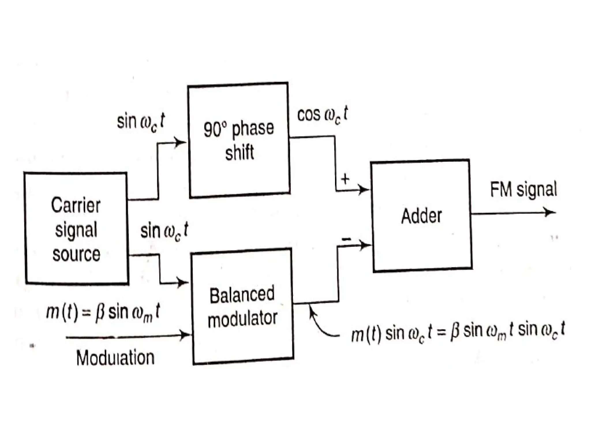
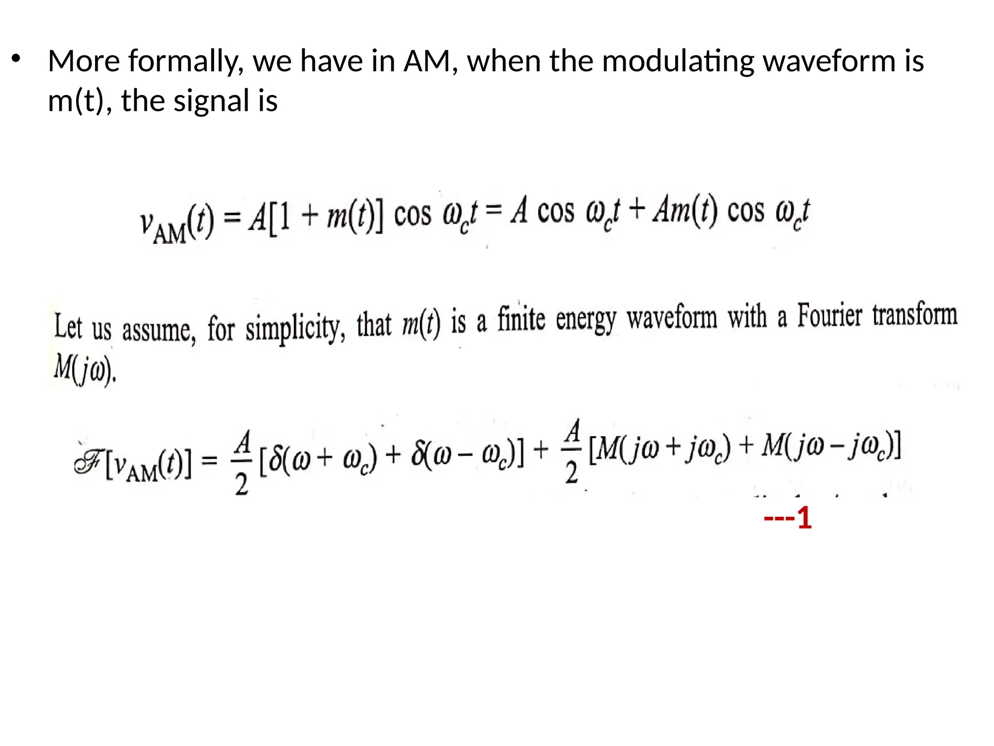
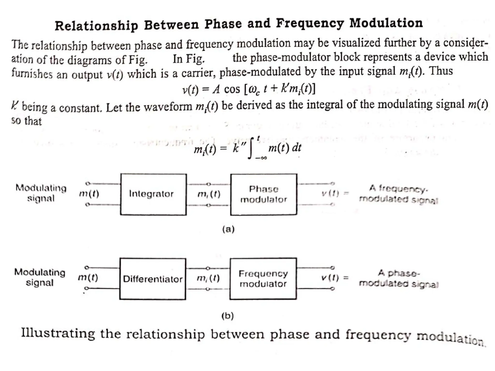
• A frequency-modulated waveform in which the
modulating waveform is m(t) is written
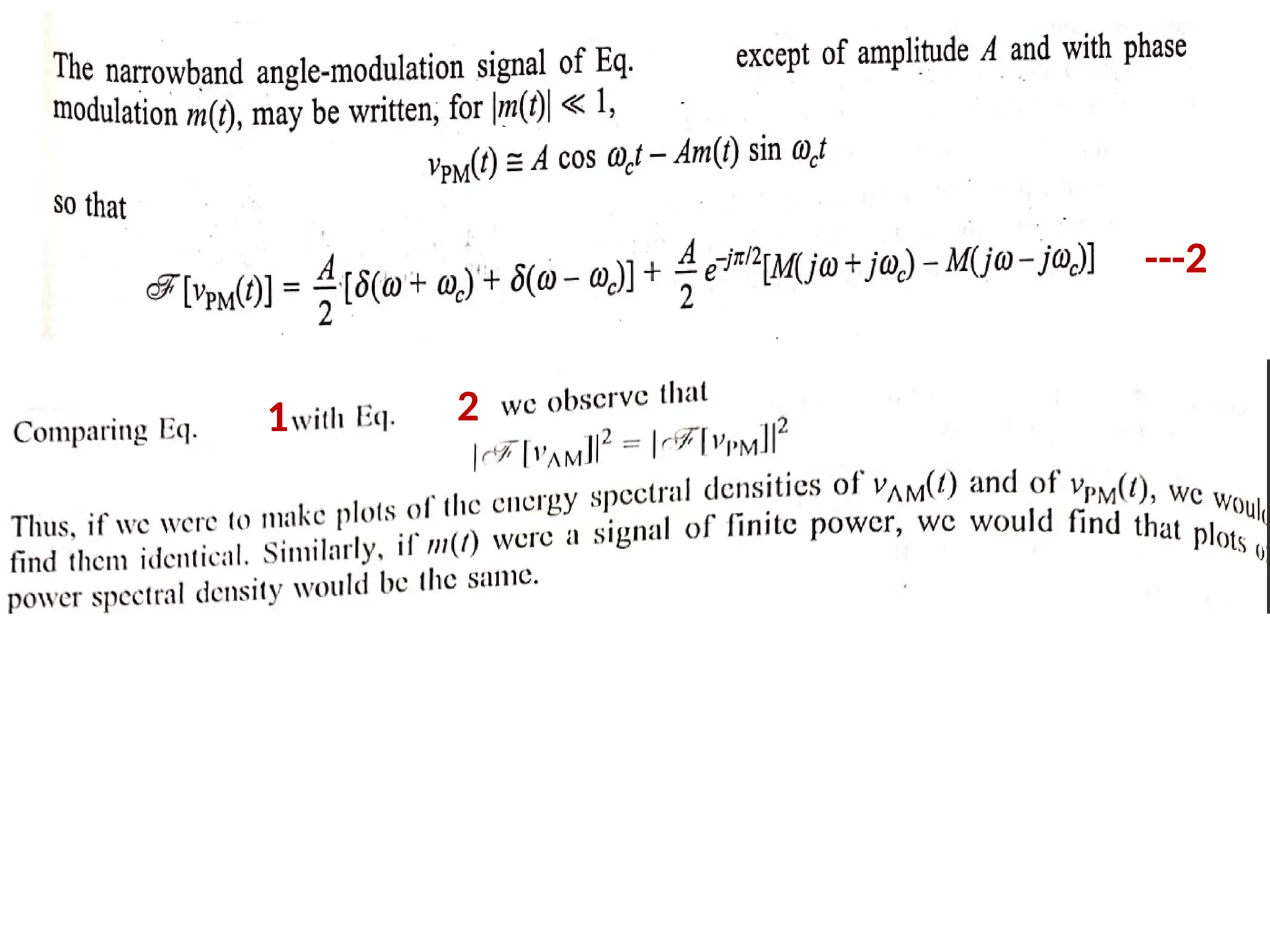
cos [ωct +m(t)] if the modulation is narrowband [|
m(t)|« 1], then we may use the approximation
• The term m(t) sin ωct is a DSB-SC waveform in which
m(t) is the modulating waveform and sin ωct the
carrier.](https://image.slidesharecdn.com/pcsunit2-240816152844-9e27cd7a/75/principals-of-communication-system-unit-2-material-9-2048.jpg)