Download as PDF, PPTX
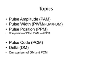

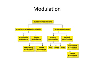
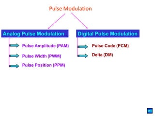
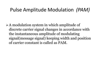
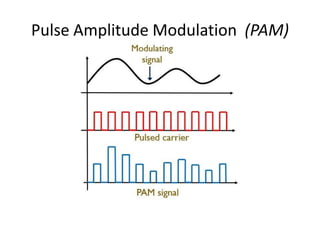

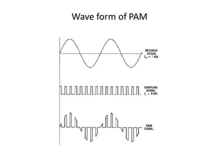
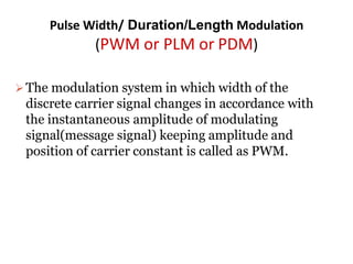
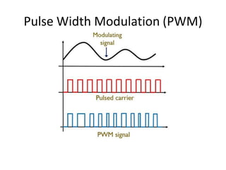
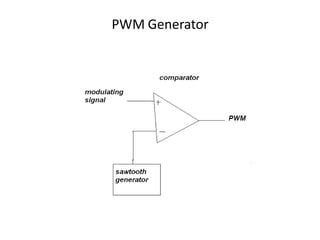
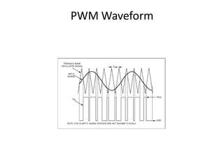
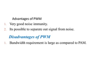
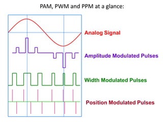

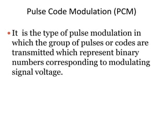
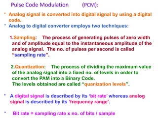
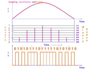
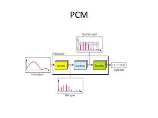
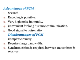
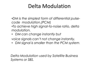
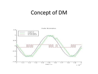
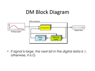
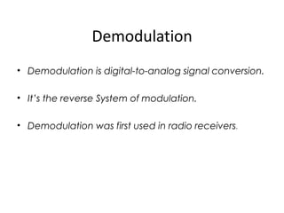
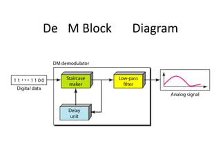
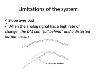


The document provides an overview of various pulse modulation techniques, including Pulse Amplitude Modulation (PAM), Pulse Width Modulation (PWM), Pulse Position Modulation (PPM), Pulse Code Modulation (PCM), and Delta Modulation (DM). Each modulation type is described in terms of its mechanisms, advantages, disadvantages, and comparisons regarding noise immunity, bandwidth requirements, and signal synchronization. The text also highlights key differences between analog and digital signals, particularly in the context of PCM and DM's functionalities.