The document provides a comprehensive overview of angle modulation, particularly focusing on frequency modulation (FM) and phase modulation (PM), highlighting their definitions, advantages over amplitude modulation (AM), applications, and methods of generation and demodulation. It explains the mathematical relationships involved in both modulation types, including the generation of FM waves through indirect and direct methods. Additionally, it discusses FM stereo multiplexing and the process for recovering audio signals, emphasizing its feasibility in commercial broadcasting.
![INTRODUCTION
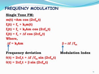
s(t) =Ac cos[θ(t)]
Instantaneous frequency of angle modulated wave s(t) is
given by,
fi(t) =(1/2π)dθ(t)/dt
In the case of an un-modulated carrier, the angle
becomes
θ(t) = 2πfct + fc
3
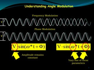
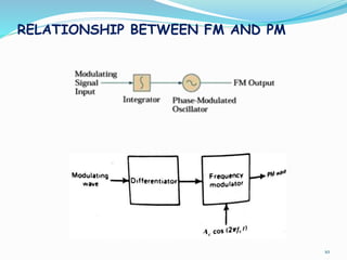
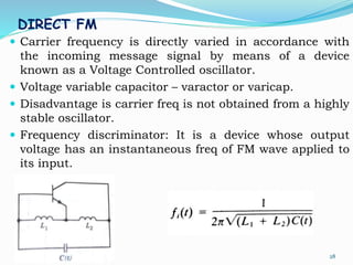
• Angle modulation is the process by which the angle
(frequency or phase) of the carrier signal is changed in
accordance with the message signal](https://image.slidesharecdn.com/module-2-linkleden-190607081755/85/Angle-Modulation-3-320.jpg)
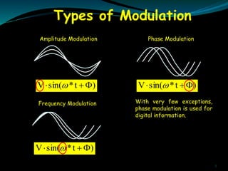
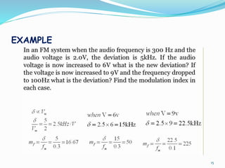
![PHASE MODULATION
Form of angle modulation in which the angular
argument q(t) is varied linearly with the message signal
m(t).
q(t) = 2pfct + kpm(t)
S(t) = Accos [2pfct + kpm(t)]
6
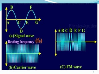
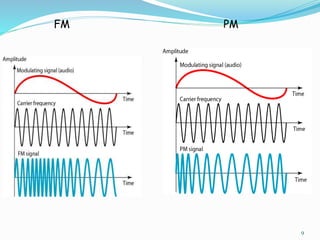
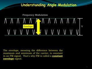
FREQUENCY MODULATION
• Form of angle modulation in which the instantaneous
frequency fi(t) is varied linearly with the message signal m(t).
fi(t) = fc + kfm(t)
S(t) = Ac cos [2pfct + 2pkf ∫m(t) dt]](https://image.slidesharecdn.com/module-2-linkleden-190607081755/85/Angle-Modulation-6-320.jpg)
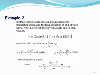
![SPECTRUM ANALYSIS OF SINUSOIDAL FM
WAVE
s(t) = Ac cos[2pfct + b sin (2pfmt)]
sI(t) = Ac cos[b sin (2pfmt)]
sQ(t) = Ac sin[b sin (2pfmt)]
...
…
This is the desired Fourier series representation of the
single tone FM wave s(t).
18
n
mcnc tnffJAts ])(2cos[)()( pb](https://image.slidesharecdn.com/module-2-linkleden-190607081755/85/Angle-Modulation-18-320.jpg)
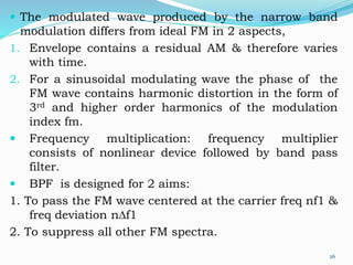
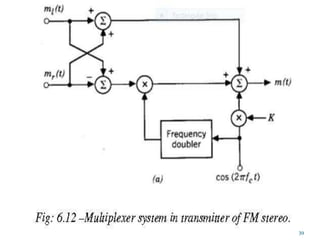
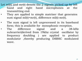
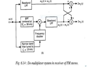
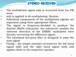
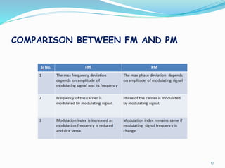
![• In addition to sum signal and DSBSC
modulated wave , the multiplexed signal m(t)
also includes a 19khz signal to provide
reference for coherent detection of the
difference signal at the stereo receiver.
• Thus the multiplexed signal is given by:
m(t)=[ml(t)+mr(t)]+[ml(t)-mr(t)] cos (4пfct) +
K cos (2пfct).
41](https://image.slidesharecdn.com/module-2-linkleden-190607081755/85/Angle-Modulation-40-320.jpg)