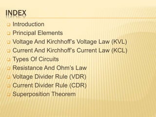
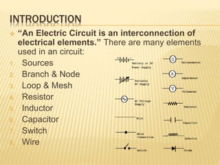
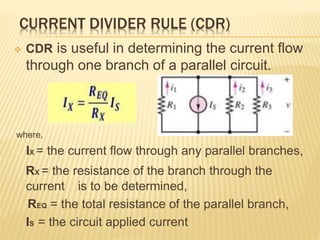
Fundamentals
Of
Electric circuits
INDEX
 Introduction
 Principal Elements
 Voltage And Kirchhoff’s Voltage Law (KVL)
 Current And Kirchhoff’s Current Law (KCL)
 Types Of Circuits
 Resistance And Ohm’s Law
 Voltage Divider Rule (VDR)
 Current Divider Rule (CDR)
 Superposition Theorem
INTRODUCTION
 “An Electric Circuit is an interconnection of
electrical elements.” There are many elements
used in an circuit:
1. Sources
2. Branch & Node
3. Loop & Mesh
4. Resistor
5. Inductor
6. Capacitor
7. Switch
8. Wire
DEPENDENT SOURCE:
1. Dependent Sources are whose input (current or
voltage) is a function of some other voltage or
current in a circuit.
2. The symbols typically used to represent
dependent sources are in the shape of a
diamond.
INDEPENDENT SOURCE:
1. Independent Sources have the capability of
generating a prescribed voltage or current
independent of any other element within the
circuit.
2. These sources may output constant
voltage/current that varies with time.
BRANCH & NODE
 Branch is any portion of
circuit with two terminals
connected with it. It may
consist of one or more
circuit elements.
 Node is the point of
connection between two
or more branches. A
node usually indicated
by a dot in a circuit.
LOOP & MESH
 Loop is any closed path
through the circuit in
which no node is
encountered more than
once.
 Mesh is a loop that does
not contain any other
loops.
VOLTAGE & KVL
 Voltage is the total work per unit charge associated
with the motion of charge between two points. The
unit of voltage is Volt (v).
 Kirchhoff’s Voltage Law (KVL) states that, “The net
voltage around a closed circuit is zero.” This
means, algebraic sum of the potential rises and
drops around a closed loop or path is zero.
CURRENT & KCL
 Current is defined as the time rate of change of
charge passing through a predetermined area. The
unit of electric current is called Ampere (A).
 Kirchhoff’s Current Law (KCL) states that, “The
sum of the currents at a node must equal to
zero.” That means, the algebraic sum of current
entering and leaving a node is equal to zero.
or
RESISTANCE & OHM’S LAW
 An ideal Resistor is a device that exhibits
linear resistance properties according to
Ohm’s Law, which states that, “The voltage
across a resistance is directly
proportional to the current flowing
through it.”
V = IR
where R is resistance, whose unit is
measured
in Ohm.
TYPES OF CIRCUIT
 Open Circuit: A circuit
element whose
resistance approaches
infinity.
 Short Circuit: A circuit
element whose
resistance approaches
zero.
SERIES CIRCUIT
 Two or more circuit elements are said to be
in Series if the current from one element
exclusively flows in to the next elements. All
series elements have the same current and
there is only one common point between two
elements.
PARALLEL CIRCUIT
 Two or more circuit elements are said to be
in Parallel if the elements share the same
terminals. All parallel elements have the
same voltage and there is more than one
common point between two elements.
VOLTAGE DIVIDER RULE
 VDR is useful in determining the voltage drop
across a resistance within a series circuit.
Where,
VX = the voltage drop across the measured resistor,
RX = the voltage drop across the measured resistor,
REQ = the circuit total resistance,
VS = the circuit applied voltage
CURRENT DIVIDER RULE (CDR)
 CDR is useful in determining the current flow
through one branch of a parallel circuit.
where,
IX = the current flow through any parallel branches,
RX = the resistance of the branch through the
current is to be determined,
REQ = the total resistance of the parallel branch,
IS = the circuit applied current
Fundamentals of-electric-circuit

Fundamentals of-electric-circuit

  • 1.
  • 2.
    INDEX  Introduction  PrincipalElements  Voltage And Kirchhoff’s Voltage Law (KVL)  Current And Kirchhoff’s Current Law (KCL)  Types Of Circuits  Resistance And Ohm’s Law  Voltage Divider Rule (VDR)  Current Divider Rule (CDR)  Superposition Theorem
  • 3.
    INTRODUCTION  “An ElectricCircuit is an interconnection of electrical elements.” There are many elements used in an circuit: 1. Sources 2. Branch & Node 3. Loop & Mesh 4. Resistor 5. Inductor 6. Capacitor 7. Switch 8. Wire
  • 4.
    DEPENDENT SOURCE: 1. DependentSources are whose input (current or voltage) is a function of some other voltage or current in a circuit. 2. The symbols typically used to represent dependent sources are in the shape of a diamond.
  • 5.
    INDEPENDENT SOURCE: 1. IndependentSources have the capability of generating a prescribed voltage or current independent of any other element within the circuit. 2. These sources may output constant voltage/current that varies with time.
  • 6.
    BRANCH & NODE Branch is any portion of circuit with two terminals connected with it. It may consist of one or more circuit elements.  Node is the point of connection between two or more branches. A node usually indicated by a dot in a circuit.
  • 7.
    LOOP & MESH Loop is any closed path through the circuit in which no node is encountered more than once.  Mesh is a loop that does not contain any other loops.
  • 8.
    VOLTAGE & KVL Voltage is the total work per unit charge associated with the motion of charge between two points. The unit of voltage is Volt (v).  Kirchhoff’s Voltage Law (KVL) states that, “The net voltage around a closed circuit is zero.” This means, algebraic sum of the potential rises and drops around a closed loop or path is zero.
  • 9.
    CURRENT & KCL Current is defined as the time rate of change of charge passing through a predetermined area. The unit of electric current is called Ampere (A).  Kirchhoff’s Current Law (KCL) states that, “The sum of the currents at a node must equal to zero.” That means, the algebraic sum of current entering and leaving a node is equal to zero. or
  • 10.
    RESISTANCE & OHM’SLAW  An ideal Resistor is a device that exhibits linear resistance properties according to Ohm’s Law, which states that, “The voltage across a resistance is directly proportional to the current flowing through it.” V = IR where R is resistance, whose unit is measured in Ohm.
  • 11.
    TYPES OF CIRCUIT Open Circuit: A circuit element whose resistance approaches infinity.  Short Circuit: A circuit element whose resistance approaches zero.
  • 12.
    SERIES CIRCUIT  Twoor more circuit elements are said to be in Series if the current from one element exclusively flows in to the next elements. All series elements have the same current and there is only one common point between two elements.
  • 13.
    PARALLEL CIRCUIT  Twoor more circuit elements are said to be in Parallel if the elements share the same terminals. All parallel elements have the same voltage and there is more than one common point between two elements.
  • 14.
    VOLTAGE DIVIDER RULE VDR is useful in determining the voltage drop across a resistance within a series circuit. Where, VX = the voltage drop across the measured resistor, RX = the voltage drop across the measured resistor, REQ = the circuit total resistance, VS = the circuit applied voltage
  • 15.
    CURRENT DIVIDER RULE(CDR)  CDR is useful in determining the current flow through one branch of a parallel circuit. where, IX = the current flow through any parallel branches, RX = the resistance of the branch through the current is to be determined, REQ = the total resistance of the parallel branch, IS = the circuit applied current

Editor's Notes

  • #6 An independent voltage source  maintains a voltage (fixed or varying with time) which is not affected by any other quantity. Similarly an independent current source  maintains a current (fixed or time-varying) which is unaffected by any other quantity. The usual symbols are shown in figure