BASIC LAWS
1. OHM’SLAW
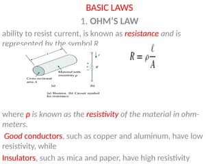
ability to resist current, is known as resistance and is
represented by the symbol R
where ρ is known as the resistivity of the material in ohm-
meters.
Good conductors, such as copper and aluminum, have low
resistivity, while
Insulators, such as mica and paper, have high resistivity
2.
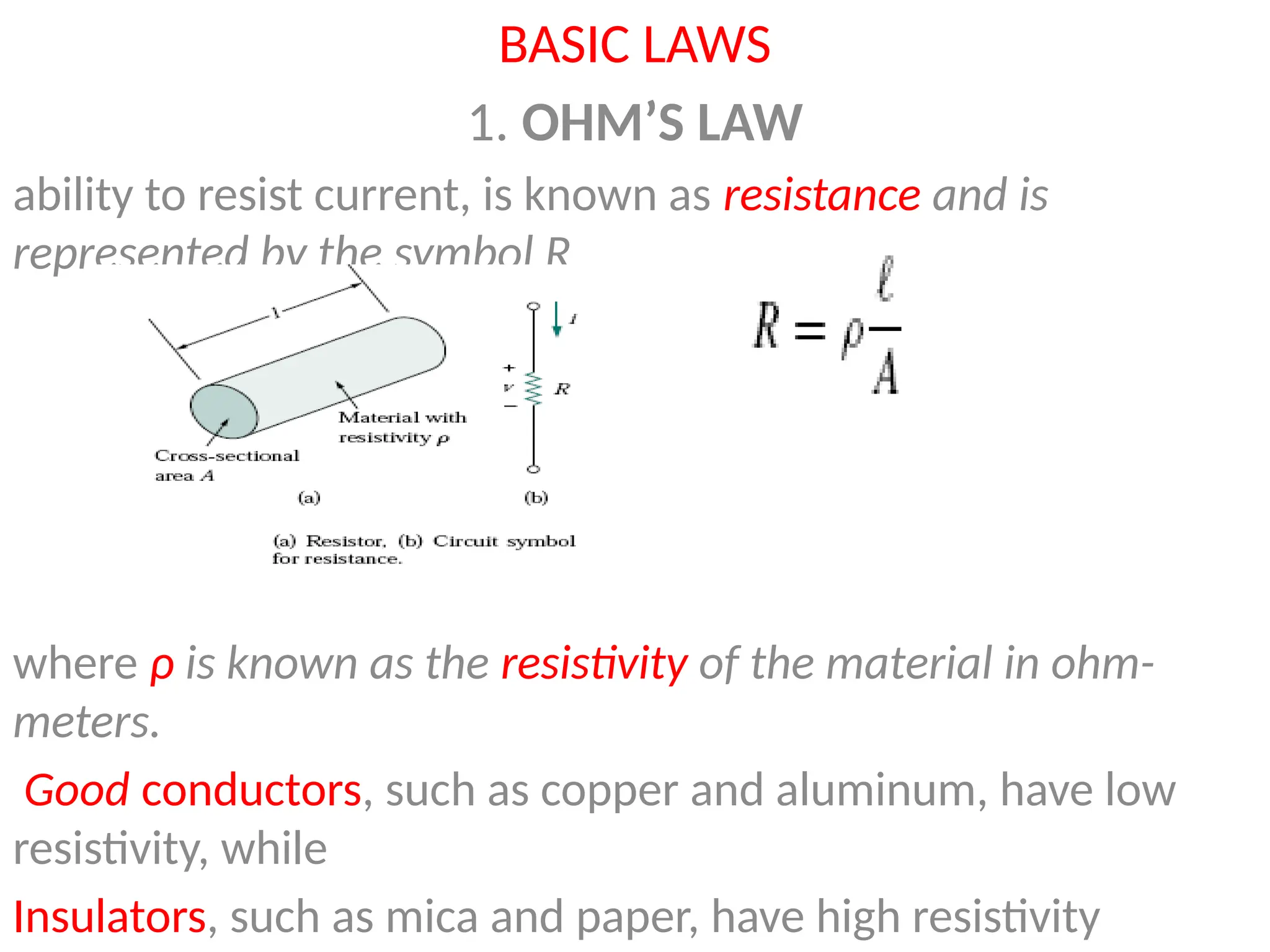
Ohm’s law statesthat the voltage v across a resistor is directly
proportional to the current i flowing through the resistor.
A short circuit is a circuit element with resistance approaching
zero ,so the voltage drop v = iR = 0
An open circuit is a circuit element with resistance approaching infinity.
3.
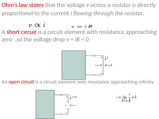
the reciprocal ofresistance R, known as conductance and denoted by G:
Conductance is the ability of an element to conduct electric current; it is
measured in mhos or Siemens (S).
4.
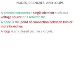
NODES, BRANCHES, ANDLOOPS
A branch represents a single element such as a
voltage source or a resistor etc.
A node is the point of connection between two or
more branches.
A loop is any closed path in a circuit.
5.
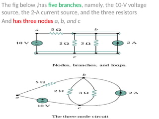
The fig below,has five branches, namely, the 10-V voltage
source, the 2-A current source, and the three resistors
And has three nodes a, b, and c
6.
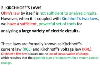
2. KIRCHHOFF’S LAWS
Ohm’slaw by itself is not sufficient to analyze circuits.
However, when it is coupled with Kirchhoff’s two laws,
we have a sufficient, powerful set of tools for
analyzing a large variety of electric circuits.
These laws are formally known as Kirchhoff’s
current law (KCL) and Kirchhoff’s voltage law (KVL).
Kirchhoff’s first law is based on the law of conservation of charge,
which requires that the algebraic sum of charges within a system cannot
change.
7.
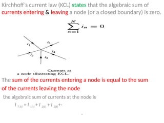
Kirchhoff’s current law(KCL) states that the algebraic sum of
currents entering & leaving a node (or a closed boundary) is zero.
The sum of the currents entering a node is equal to the sum
of the currents leaving the node
the algebraic sum of currents at the node is
I T (t) = I 1(t) + I 2(t) + I 3(t)+·
.
8.
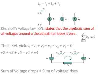
IT = I1− I2 + I3
Kirchhoff’s voltage law (KVL) states that the algebraic sum of
all voltages around a closed path(or loop) is zero.
Thus, KVL yields, −v1 + v2 + v3 − v4 + v5 = 0
v2 + v3 + v5 = v1 + v4
Sum of voltage drops = Sum of voltage rises
9.
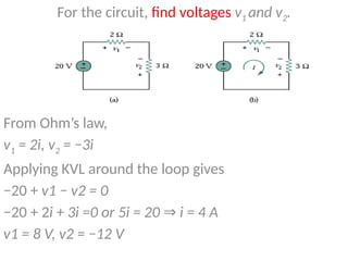
For the circuit,find voltages v1 and v2.
From Ohm’s law,
v1 = 2i, v2 = −3i
Applying KVL around the loop gives
−20 + v1 − v2 = 0
−20 + 2i + 3i =0 or 5i = 20 i = 4 A
⇒
v1 = 8 V, v2 = −12 V
10.
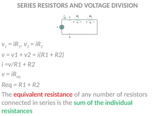
SERIES RESISTORS ANDVOLTAGE DIVISION
v1 = iR1, v2 = iR2
v = v1 + v2 = i(R1 + R2)
i =v/R1 + R2
v = iReq
Req = R1 + R2
The equivalent resistance of any number of resistors
connected in series is the sum of the individual
resistances
11.
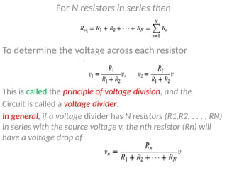
For N resistorsin series then
To determine the voltage across each resistor
This is called the principle of voltage division, and the
Circuit is called a voltage divider.
In general, if a voltage divider has N resistors (R1,R2, . . . , RN)
in series with the source voltage v, the nth resistor (Rn) will
have a voltage drop of
12.
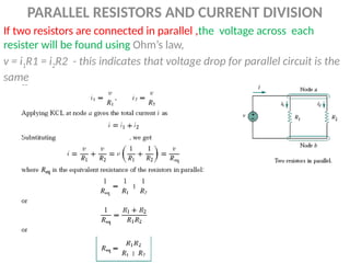
PARALLEL RESISTORS ANDCURRENT DIVISION
If two resistors are connected in parallel ,the voltage across each
resister will be found using Ohm’s law,
v = i1R1 = i2R2 - this indicates that voltage drop for parallel circuit is the
same
13.
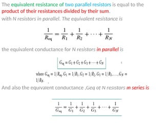
The equivalent resistanceof two parallel resistors is equal to the
product of their resistances divided by their sum.
with N resistors in parallel. The equivalent resistance is
the equivalent conductance for N resistors in parallel is
And also the equivalent conductance ,Geq of N resistors in series is
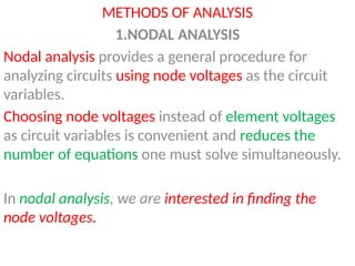
METHODS OF ANALYSIS
1.NODALANALYSIS
Nodal analysis provides a general procedure for
analyzing circuits using node voltages as the circuit
variables.
Choosing node voltages instead of element voltages
as circuit variables is convenient and reduces the
number of equations one must solve simultaneously.
In nodal analysis, we are interested in finding the
node voltages.
16.
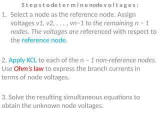
S t ep s t o de t e r m i n e node v o l t a g e s :
1. Select a node as the reference node. Assign
voltages v1, v2, . . . , vn−1 to the remaining n − 1
nodes. The voltages are referenced with respect to
the reference node.
2. Apply KCL to each of the n − 1 non-reference nodes.
Use Ohm’s law to express the branch currents in
terms of node voltages.
3. Solve the resulting simultaneous equations to
obtain the unknown node voltages.
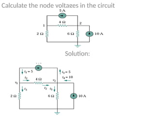
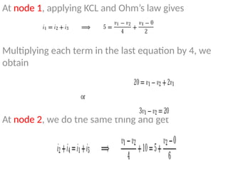
At node 1,applying KCL and Ohm’s law gives
Multiplying each term in the last equation by 4, we
obtain
At node 2, we do the same thing and get
19.
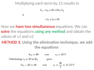
Multiplying each termby 12 results in
Now we have two simultaneous equations. We can
solve the equations using any method and obtain the
values of v1 and v2.
METHOD 1: Using the elimination technique, we add
the equations
20.
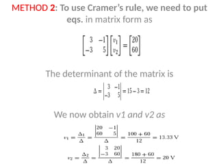
METHOD 2: Touse Cramer’s rule, we need to put
eqs. in matrix form as
The determinant of the matrix is
We now obtain v1 and v2 as
21.
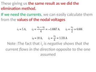
These giving usthe same result as we did the
elimination method.
If we need the currents, we can easily calculate them
from the values of the nodal voltages
Note :The fact that i2 is negative shows that the
current flows in the direction opposite to the one
assumed
22.
MESH ANALYSIS
Mesh analysisprovides another general procedure for
analyzing circuits, using mesh currents as the circuit variables.
Using mesh currents instead of element currents as circuit
variables is convenient and reduces the
number of equations that must be solved simultaneously.
Recall that a loop is a closed path with no node passed more
than once. A mesh is a loop that does not contain any other
loop within it.
Note :Mesh analysis is also known as loop analysis or the
mesh-current method.
Nodal analysis applies KCL to find unknown voltages in a given
circuit, while mesh analysis applies KVL to find unknown
currents.
23.
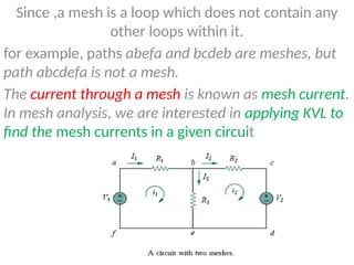
Since ,a meshis a loop which does not contain any
other loops within it.
for example, paths abefa and bcdeb are meshes, but
path abcdefa is not a mesh.
The current through a mesh is known as mesh current.
In mesh analysis, we are interested in applying KVL to
find the mesh currents in a given circuit
24.
S t ep s t o D e t e r m i n e Mesh C u r r e n t s :
1. Assign mesh currents i1, i2, . . . , in to the n meshes.
2. Apply KVL to each of the n meshes. Use Ohm’s law to express the voltages in terms
of the mesh currents.
3. Solve the resulting n simultaneous equations to get the mesh currents
For exam:
The first step requires that mesh currents i1 and i2 are assigned to meshes 1 and
2.
As the second step, we apply KVL to each mesh. Applying KVL to mesh 1, we obtain
For mesh 2, applying KVL gives
25.
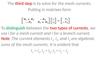
The third stepis to solve for the mesh currents.
Putting in matrixes form
To distinguish between the two types of currents, we
use i for a mesh current and I for a branch current.
Note :The current elements I1, I2, and I3 are algebraic
sums of the mesh currents. It is evident that
I1 = i1, I2 = i2, I3 = i1 − i2
26.
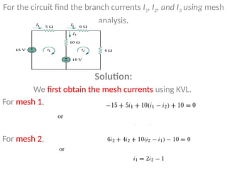
For the circuitfind the branch currents I1, I2, and I3 using mesh
analysis.
Solution:
We first obtain the mesh currents using KVL.
For mesh 1,
For mesh 2,
27.
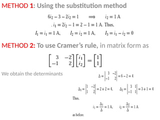
METHOD 1: Usingthe substitution method
METHOD 2: To use Cramer’s rule, in matrix form as
We obtain the determinants