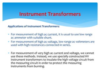
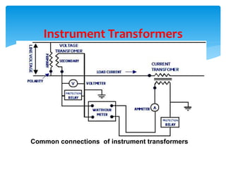
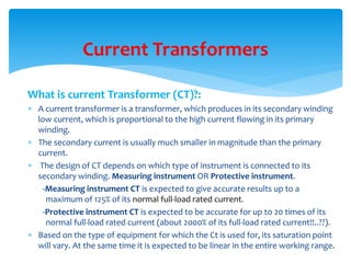
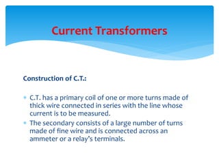
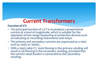
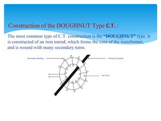
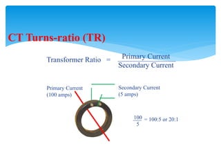
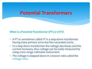
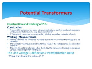
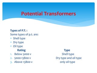
The document provides information about instrument transformers, specifically current transformers (CTs) and potential transformers (PTs). It discusses their construction, working principles, applications, specifications, and connections. CTs are used to measure high currents by producing a proportional low current in their secondary winding. PTs are step-down transformers that allow measurement of high voltages using low-range voltmeters. Proper use and specifications of these transformers are important to ensure accurate measurements and avoid issues like saturation.
Design factors; Limitations; Modern trends; Electrical
Engineering Materials; Space factor; Choice of Specific
Electric and Magnetic loadings; Thermal Considerations;
Heat flow; Temperature rise; Insulating Materials; Properties;
Rating of Machines; Various Standard Specifications ;
Design factors; Limitations; Modern trends; Electrical
Engineering Materials; Space factor; Choice of Specific
Electric and Magnetic loadings; Thermal Considerations;
Heat flow; Temperature rise; Insulating Materials; Properties;
Rating of Machines; Various Standard Specifications ;
In this slide I have explained how two watt meters can be used to measure 3 phase power. Some of the added advantage of this method is that we can calculate 3 phase reactive power and power factor of load as well.
ELECTRICAL MEASUREMENT & MEASURING INSTRUMENTS [Emmi- (NEE-302) -unit-1]Md Irshad Ahmad
(1) Philosophy of Measurement-Methods of measurement, Measurement system
, Classification of instrument systems, Characteristics of instruments & measurement
systems, Errors in measurement & its analysis, Standards.
(2)Analog Measurement of Electrical Quantities-Electrodynamic, Thermocouple,
Electrostatic & Rectifier type ammeters & voltmeters, Electrodynamic wattmeter, Three
Phase wattmeter, Power in three phase systems, Errors & remedies in wattmeter and energy
meter.
Current Transformer and Potential TransformerRidwanul Hoque
One of the major difference between them is that the current transformer converts the high value of current into low value whereas the potential or voltage transformer converts the high value of voltages into low voltage.
Generator and Transformer Protection (PART 1)Dr. Rohit Babu
Part 1. Generator Protection
Protection of generators against stator faults
Rotor faults and abnormal conditions
Restricted earth fault and inter-turn fault protection
Numerical examples
Today, nearly every piece of electrical equipment generates harmonic currents and voltages. This Application Note gives a comprehensive and up-to-date overview of the subject. It explains why harmonic problems have been increasing over recent years, how they are generated, and by which type of equipment. It presents an overview of the various problems harmonic currents can create. Most of them are either related to different kinds of overloading – leading to problems of efficiency loss and overheating – or to disturbances of control and safety devices.
This Application Note also presents a brief overview of the available solutions. The four main mitigation solutions are passive shunt filters, passive series filters, isolation transformers, and active harmonic conditioners. The Application Note concludes that good design practice, the right electrical equipment, and good maintenance are the keys to preventing future problems.
Learn about Instrument transformers, current transformers, and potential transformers in this presentation given by Georgia Power at the Caribbean Meter School. 01/29/2019
It is based on current transformer description
It's working and applications are present in it ,it also includes videos of it's windings and it's inrush ability of transformer, and also about instrument transformer and it's working with applications.Current transformers are used-in measuring high currents and connected with it in parallel to it
CT and PT Instrument transformer | basic information with some most asked que...AkhileshDeshmukh5
This ppt contains all basic information about instrument transformer le CT and PT which is explained in baase manner. In this ppt, you will also get to learn about questions which are asked in the interview about CT and PT.
UNIT-V:Non Conventional Energy Sources:
Power Crisis, future energy demand, role of Private sectors in energy management,
concepts & principals of MHD generation, Solar power plant,
Wind Energy,Geothermal Energy,Tidal energy,Ocean Thermal Energy.
UNIT-IV:Economic Operation of Power Systems:
Characteristics of steam and hydro-plants,Constraints in operation, Economic load scheduling of thermal plants Neglecting and considering transmission Losses, Penalty factor, loss coefficients, Incremental transmission loss. Hydrothermal Scheduling.
UNIT-III:Sub-stations Layout:
Types of substations, bus-bar arrangements, typical layout of substation.Power Plant Economics and Tariffs:Load curve, load duration curve, different factors related to plants and consumers, Cost of electrical energy, depreciation, generation cost, effect of Load factor on unit cost. Fixed and operating cost of different plants, role of load diversity in power system economy. Objectives and forms of Tariff; Causes and effects of low power factor, advantages of power factor improvement, different methods for power factor improvements.
UNIT-II: Nuclear Power Plant:
Location, site selection, general layout and operation of plant. Brief description of different types of reactors Moderator material, fissile materials, control of nuclear reactors, disposal of nuclear waste material, shielding.Gas Turbine Plant: Operational principle of gas turbine plant & its efficiency, fuels, open and closed-cycle plants, regeneration, inter-cooling and reheating, role and applications.
Diesel Plants:
Diesel plant layout, components & their functions, its performance, role and applications.
UNIT-I:Introduction:
Electric energy demand and growth in India, electric energy sources.
Thermal Power Plant: Site selection, general layout and operation of plant, detailed description and use of different parts.
Hydro Electric Plants: Classifications, location and site selection, detailed description of various components, general layout and operation of Plants, brief description of impulse, reaction, Kaplan and Francis turbines, advantages & disadvantages, hydro-potential in India.
Electrical measurement & measuring instruments [emmi (nee-302) -unit-5]Md Irshad Ahmad
(1) Digital Measurement of Electrical Quantities-Concept of digital measurement, Block diagram, Study of digital voltmeter, Frequency meter, Spectrum analyzer, Electronic multimeter.
(2) Cathode Ray Oscilloscope-Basic CRO circuit (block diagram), Cathode Ray Tube (CRT)
& its components,Applications of CRO in measurement, Lissajous Pattern, Dual trace & dual beam oscilloscopes.
Electrical measurement & measuring instruments [emmi (nee-302) -unit-4]Md Irshad Ahmad
AC Potentiometers-Polar type & Co-ordinate type AC potentiometers, application of AC
Potentiometers inelectrical measurement. (4)
(2)Magnetic Measurement-Ballistic galvanometer, Flux meter ,Determination of hysteresis
loop, measurement of iron losses.
Electrical measurement & measuring instruments [emmi (nee-302) -unit-3]Md Irshad Ahmad
Measurement of Parameters-Different methods of measuring low, medium and high resistances, measurement of inductance & capacitance with the help of AC Bridges, Q meter
Unit-V
Measurement and Solving of Power Quality Problems: Power quality measurement devices- Harmonic Analyzer , Transient Disturbance Analyzer, wiring and grounding tester, Flicker Meter, Oscilloscope, multi-meter etc. Introduction to Custom Power Devices-Network Reconfiguration devices; Load compensation and voltage regulation using DSTATCOM; protecting sensitive loads using DVR; Unified power Quality Conditioner. (UPQC)
Unit-IV
Harmonics: Causes of harmonics; current and voltage harmonics: measurement of harmonics; effects of harmonics on – Transformers, AC Motors, Capacitor Banks, Cables, and Protection
Devices, Energy Metering, Communication Lines etc. harmonic mitigation techniques
Unit-III
Electrical Transients: Sources of Transient Over voltages- Atmospheric and switching transients- motor starting transients, pf correction capacitor switching transients, ups switching transients, neutral voltage swing etc; devices for over voltage protection
Unit-II
Voltage Sag: Sources of voltage sag: motor starting, arc furnace, fault clearing etc; estimating voltage sag performance and principle of its protection; solutions at end user level- Isolation Transformer, Voltage Regulator, Static UPS, Rotary UPS, Active Series Compensator
Introduction to Power Quality: Terms and definitions of transients,
Long Duration Voltage Variations: under Voltage, Under Voltage and Sustained Interruptions
; Short Duration Voltage Variations: interruption, Sag, Swell; Voltage Imbalance; Notching D C offset,; waveform distortion; voltage fluctuation; power frequency variations
Protection of Transformer
Generator and motor.
Circuit Breaker: Operating modes
Selection of circuit breakers
Constructional features and operation of Bulk Oil,
Minimum Oil,
Air Blast,
SF6,
Vacuum and d. c. circuit breakers.
Circuit Breaking:
Properties of arc
Arc extinction theories
Re-striking voltage transient
Current chopping
Resistance switching
Capacitive current interruption
Short line interruption
Circuit breaker ratings.
Testing Of Circuit Breaker: Classification
Testing station and equipment's
Testing procedure
Direct and indirect testing
Amplitude and phase comparators
Over current relays
Directional relays
Distance relays
Differential relay.
Static Relays: Comparison with electromagnetic relay
Classification and their description
Over current relays
Directional relay
Distance relays
Differential relay
Unit I: Introduction to Protection System:
Introduction to protection system and its elements, functions of protective relaying, protective zones, primary and backup protection, desirable qualities of protective relaying, basic terminology.
Relays:
Electromagnetic, attracted and induction type relays, thermal relay, gas actuated relay, design considerations of electromagnetic relay.
Unit-II: Relay Application and Characteristics:
Amplitude and phase comparators, over current relays, directional relays, distance relays, differential relay.
Static Relays: Comparison with electromagnetic relay, classification and their description, over current relays, directional relay, distance relays, differential relay.
Unit-III Protection of Transmission Line:
Over current protection, distance protection, pilot wire protection, carrier current protection, protection of bus, auto re-closing,
Unit-IV: Circuit Breaking:
Properties of arc, arc extinction theories, re-striking voltage transient, current chopping, resistance switching, capacitive current interruption, short line interruption, circuit breaker ratings.
Testing Of Circuit Breaker: Classification, testing station and equipments, testing procedure, direct and indirect testing.
Unit-V Apparatus Protection:
Protection of Transformer, generator and motor.
Circuit Breaker: Operating modes, selection of circuit breakers, constructional features and operation of Bulk Oil, Minimum Oil, Air Blast, SF6, Vacuum and d. c. circuit breakers.
Overview of the fundamental roles in Hydropower generation and the components involved in wider Electrical Engineering.
This paper presents the design and construction of hydroelectric dams from the hydrologist’s survey of the valley before construction, all aspects and involved disciplines, fluid dynamics, structural engineering, generation and mains frequency regulation to the very transmission of power through the network in the United Kingdom.
Author: Robbie Edward Sayers
Collaborators and co editors: Charlie Sims and Connor Healey.
(C) 2024 Robbie E. Sayers
Hierarchical Digital Twin of a Naval Power SystemKerry Sado
A hierarchical digital twin of a Naval DC power system has been developed and experimentally verified. Similar to other state-of-the-art digital twins, this technology creates a digital replica of the physical system executed in real-time or faster, which can modify hardware controls. However, its advantage stems from distributing computational efforts by utilizing a hierarchical structure composed of lower-level digital twin blocks and a higher-level system digital twin. Each digital twin block is associated with a physical subsystem of the hardware and communicates with a singular system digital twin, which creates a system-level response. By extracting information from each level of the hierarchy, power system controls of the hardware were reconfigured autonomously. This hierarchical digital twin development offers several advantages over other digital twins, particularly in the field of naval power systems. The hierarchical structure allows for greater computational efficiency and scalability while the ability to autonomously reconfigure hardware controls offers increased flexibility and responsiveness. The hierarchical decomposition and models utilized were well aligned with the physical twin, as indicated by the maximum deviations between the developed digital twin hierarchy and the hardware.
Student information management system project report ii.pdfKamal Acharya
Our project explains about the student management. This project mainly explains the various actions related to student details. This project shows some ease in adding, editing and deleting the student details. It also provides a less time consuming process for viewing, adding, editing and deleting the marks of the students.
About
Indigenized remote control interface card suitable for MAFI system CCR equipment. Compatible for IDM8000 CCR. Backplane mounted serial and TCP/Ethernet communication module for CCR remote access. IDM 8000 CCR remote control on serial and TCP protocol.
• Remote control: Parallel or serial interface.
• Compatible with MAFI CCR system.
• Compatible with IDM8000 CCR.
• Compatible with Backplane mount serial communication.
• Compatible with commercial and Defence aviation CCR system.
• Remote control system for accessing CCR and allied system over serial or TCP.
• Indigenized local Support/presence in India.
• Easy in configuration using DIP switches.
Technical Specifications
Indigenized remote control interface card suitable for MAFI system CCR equipment. Compatible for IDM8000 CCR. Backplane mounted serial and TCP/Ethernet communication module for CCR remote access. IDM 8000 CCR remote control on serial and TCP protocol.
Key Features
Indigenized remote control interface card suitable for MAFI system CCR equipment. Compatible for IDM8000 CCR. Backplane mounted serial and TCP/Ethernet communication module for CCR remote access. IDM 8000 CCR remote control on serial and TCP protocol.
• Remote control: Parallel or serial interface
• Compatible with MAFI CCR system
• Copatiable with IDM8000 CCR
• Compatible with Backplane mount serial communication.
• Compatible with commercial and Defence aviation CCR system.
• Remote control system for accessing CCR and allied system over serial or TCP.
• Indigenized local Support/presence in India.
Application
• Remote control: Parallel or serial interface.
• Compatible with MAFI CCR system.
• Compatible with IDM8000 CCR.
• Compatible with Backplane mount serial communication.
• Compatible with commercial and Defence aviation CCR system.
• Remote control system for accessing CCR and allied system over serial or TCP.
• Indigenized local Support/presence in India.
• Easy in configuration using DIP switches.
Sachpazis:Terzaghi Bearing Capacity Estimation in simple terms with Calculati...Dr.Costas Sachpazis
Terzaghi's soil bearing capacity theory, developed by Karl Terzaghi, is a fundamental principle in geotechnical engineering used to determine the bearing capacity of shallow foundations. This theory provides a method to calculate the ultimate bearing capacity of soil, which is the maximum load per unit area that the soil can support without undergoing shear failure. The Calculation HTML Code included.
Final project report on grocery store management system..pdfKamal Acharya
In today’s fast-changing business environment, it’s extremely important to be able to respond to client needs in the most effective and timely manner. If your customers wish to see your business online and have instant access to your products or services.
Online Grocery Store is an e-commerce website, which retails various grocery products. This project allows viewing various products available enables registered users to purchase desired products instantly using Paytm, UPI payment processor (Instant Pay) and also can place order by using Cash on Delivery (Pay Later) option. This project provides an easy access to Administrators and Managers to view orders placed using Pay Later and Instant Pay options.
In order to develop an e-commerce website, a number of Technologies must be studied and understood. These include multi-tiered architecture, server and client-side scripting techniques, implementation technologies, programming language (such as PHP, HTML, CSS, JavaScript) and MySQL relational databases. This is a project with the objective to develop a basic website where a consumer is provided with a shopping cart website and also to know about the technologies used to develop such a website.
This document will discuss each of the underlying technologies to create and implement an e- commerce website.
Final project report on grocery store management system..pdf
Electrical measurement & measuring instruments [emmi (nee-302) -unit-2]
1. ELECTRICAL MEASUREMENT & MEASURING INSTRUMENTS (NEE-302)
Md Irshad Ahmad
irshad.ahmad@jit.edu.in
Electrical Engineering Department
LECTURE
on
UNIT –II
Instrument Transformers
2. CONTENTS
CT and PT their errors
Applications of CT and PT in the
extension of instrument range
Introduction to measurement of speed
frequency
Introduction to measurement of power
factor
3. What is an Instrument Transformer ?:
It is a transformer that is used in conjunction with any
measuring instrument (i.e., Ammeter, Voltmeter,
Wattmeter, Watt-hour-meter, …etc.)or protective
equipment (i.e., Relays).
It utilizes the current-transformation and voltage
transformation properties to measure high ac current and
voltage.
Instrument Transformers
4. Types of instrument transformers :
These instrument transformers are of two types:-
1. Current transformers
2. Potential transformers
Instrument Transformers
5. Applications of Instrument Transformers:
For measurement of high ac current, it is usual to use low range
ac ammeter with suitable shunt.
For measurement of high ac voltage, low range ac voltmeters are
used with high resistances connected in series.
For measurement of very high ac current and voltage, we cannot
use these methods. Instead, we use specially constructed HV
instrument transformers to insulate the high voltage circuit from
the measuring circuit in order to protect the measuring
instruments from burning.
Instrument Transformers
6. Application of Instrumentation Transformers In dc circuits
for current and voltage measurement, we use low range
dc ammeters and voltmeters with rectifiers connected in
their secondary circuits.
The vast primary application of Instrument Transformers
is for the protection and control of power system and
power equipment of high and very high ratings.
The working of these instrument transformers are similar
to those of the ordinary transformers.
Instrument Transformers
7. Basic Construction and Magnetic Circuit of Instrument Transformers
Instrument Transformers
10. What is current Transformer (CT)?:
A current transformer is a transformer, which produces in its secondary winding
low current, which is proportional to the high current flowing in its primary
winding.
The secondary current is usually much smaller in magnitude than the primary
current.
The design of CT depends on which type of instrument is connected to its
secondary winding. Measuring instrument OR Protective instrument.
-Measuring instrument CT is expected to give accurate results up to a
maximum of 125% of its normal full-load rated current.
-Protective instrument CT is expected to be accurate for up to 20 times of its
normal full-load rated current (about 2000% of its full-load rated current!!..??).
Based on the type of equipment for which the Ct is used for, its saturation point
will vary. At the same time it is expected to be linear in the entire working range.
Current Transformers
11. Construction of C.T.:
C.T. has a primary coil of one or more turns made of
thick wire connected in series with the line whose
current is to be measured.
The secondary consists of a large number of turns
made of fine wire and is connected across an
ammeter or a relay’s terminals.
Current Transformers
13. Function of CT:
The principal function of a CT is to produce a proportional
current at a level of magnitude, which is suitable for the
operation of low-range measuring or protective devices such
as indicating or recording instruments and relays.
The primary and secondary currents are expressed as a ratio
such as 100/5 or 1000/5 .
With a 100/5 ratio CT, 100A flowing in the primary winding will
result in 5A flowing in the secondary winding, provided that
the correct rated burden is connected to the secondary
winding.
Current Transformers
14. “Class” of a CT:
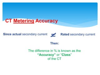
The extent to which the actual secondary current
magnitude differs from the calculated value, expected by
the virtue of the CT ratio, is defined as the accuracy “Class”
of the CT.
The greater the number used to define the class, the
greater the permissible “current error” [the deviation in
the actual secondary current from the calculated value].
Current Transformers
15. Specifications of CT:
CTs should be specified as follow:
RATIO : Input / output current ratio
VA: Total burden (rating) including pilot wires.
Common burden ratings are 2.5, 5, 10, 15 and 30 VA. For
example:
Moving iron ammeter is 1-2 VA
Moving coil rectifier ammeter is 1-2.5 VA
Electro-dynamic instrument is 2.5-5 VA
Maximum demand ammeter is 3-6 VA
Recording ammeter or transducer is 1-2.5 VA
Current Transformers
16. CLASS : The accuracy required for the operation
DIMENSIONS: Maximum & minimum limits. For example:
0.1 or 0.2 for precision measurements.
0.5 for high grade kilowatt hour meters and commercial
grade kilowatt hour meters.
3 for general industrial measurements.
3 or 5 for approximate measurements.
BURDEN (OHMIC): (Depending on pilot lead length)
Current Transformers
17. Current Transformers Stepping:
These are used with low range ammeters to measure current
in high voltage alternating circuits where it is not practical to
connect instrument and meters directly to lines.
They are step-up transformers (voltage ratio) because when
we step-up the voltage the current decreases.
The current is a step-down in a known ratio called the
current ratio .
Current Transformers
19. Multi-ratio CT:
As indicated in the previous Figure, current transformers having a center
tapped secondary are referred to as a dual ratio CT.
Dual ratio CT are used in applications where it is necessary to have
available two ratios of primary to secondary current from the same
secondary winding of the CT.
This may be accomplished by adding a tap in the secondary winding to
get a second ratio.
The ratio obtained by the tap is usually one-half the ratio obtained by the
full secondary winding.
A schematic example is previously shown with 200 amperes flowing in
the primary, a connection X2 – X3 will produce 5 amperes out of the
secondary. As the load grows to 400 amperes, the secondary circuit will
be reconnected to X1 – X3 to still produce 5 amperes in the secondary
circuit.
20. Working (Measurement):
If a current transformer has primary to secondary current ratio of 100:5
then it steps up the voltage 20 times and step down the current 1/20 times
of its actual value.
If we know the current ratio and the reading of an a.c. ammeter, the
primary current can be calculated as:
Primary Current = CT ratio × ammeter reading
Current Transformers
21. Why CT secondary should never be open ?:
Ammeter resistance is very low ,the current transformer normally works as a
short-circuited instrument.
If for any reason the ammeter is taken out of secondary winding then the
secondary winding must be short-circuited with the help of a short-circuit
switch.
If this is not done, then a high m.m.f. (Ampere-turns IT) will set up a high
flux in the magnetic core and it will produce excessive core loss which
produce heat and high voltage across the secondary terminals .
The high voltage can damage any electronic components in secondary side.
Hence the secondary of any current transformer should never be left open.
Current Transformers
22. Construction of the DOUGHNUT Type C.T. :
The most common type of C.T. construction is the “DOUGHNUT” type. It
is constructed of an iron toroid, which forms the core of the transformer,
and is wound with many secondary turns.
Secondary Winding Primary Conductor
Iron Core
23. The `doughnut' fits over the primary conductor, which constitutes one primary turn.
If the toroid is wound with 240 secondary turns, then the ratio of the C.T. is 240 : 1
or 1200 : 5A
The continuous rating of the secondary winding is normally 5 AMPS in North
America, and 1 AMP or 0.5 AMP in many other parts of the world.
This type of `doughnut' C.T. is most commonly used in circuit breakers and power
transformers. The C.T. fits into the bushing, and the porcelain bushing fits through
the centre of the `doughnut'.
Up to four C.T.'s of this type can be installed around each bushing of an oil circuit
breaker. This arrangement is shown in a following diagram.
25. Primary Current
(100 amps)
Secondary Current
(5 amps)
Primary Current
Secondary Current
Transformer Ratio = _____________________
100
5
___ = 100:5 or 20:1
CT Turns-ratio (TR)
26. Direction of
Primary Current
Direction of
Secondary Current
H1
X1
P1
IEEE
IEC
Primary
Polarity
Marks
IEEE
IECS1
Secondary
Polarity
Marks
Polarity
Primary current into “polarity” forces
Secondary current out of “polarity”
27. Direction of
Secondary Current
Direction of
Primary Current
H1
X1
P1
IEEE
IEC
Primary
Polarity
Marks
IEEE
IECS1
Secondary
Polarity
Marks
Primary current into “non-polarity” forces
Secondary current out of “non-polarity”
Polarity
28. CT Metering Accuracy
Since actual secondary current Rated secondary current
=
The difference in % is known as the
“Accuracy” or “Class”
of the CT
Then:
29. Burden
Load connected to CT secondary
Includes devices & connecting leads
Expressed in ohms
Standard values = B0.1, B0.2, B0.5, B0.9,
B1.8
E0.04, E0.2
30. CT accurate Burden Calculation
ZT = RCT + RL + ZB
ZT = Total burden in ohms (vector summation of
resistance and inductance components)
RCT = CT secondary resistance in ohms @75 deg C
RL = Resistance of leads in ohms (Total loop distance)
ZB = Device impedance in ohms
32. Factors Affecting Degree and Time to Saturation
1. High DC offset
2. High fault current Magnitude (symmetrical current)
Example:
•100 to 5 CT@20 times= 2000 amps.
•Also @20,000 amps we have 200 times CT
3. Low CT Turns Ratios
4. High secondary burden
5. Low CT Accuracy (Class)
6. High reminance flux
• Can occur if current interrupted when core is saturated
• If DC flows in windings during testing
• Need a voltage above 60% of knee point to reduce the Reminance to less than 10% of
saturation flux density.
33. Tips for Avoiding CT Saturation
1. Use higher ratio CTs
2. Use separate set of high ratio CTs for high fault current
tripping
3. Reduce secondary burden by:
-Selecting low burden relays & meters
-Distributing single phase burdens among phases
-Increasing the size of secondary leads
-Reducing the length of secondary leads
-Using “step down” auxiliary CTs
39. What is a Potential Transformer (PT) or (VT)?:
A PT or sometimes called VT is a step-down transformer
having many primary turns but few secondary turns.
In a step-down transformer the voltage decreases and the
current increases, thus voltage can be easily measured by
using a low-range voltmeter instrument.
The voltage is stepped-down in a known ratio called the
voltage ratio.
Potential Transformers
40. Construction and working of P.T.:
Construction
A potential transformer has many primary winding turns but few number of secondary
winding turns that makes it a step-down transformer.
A Voltmeter is connected to the secondary winding is usually a voltmeter of 150 V.
Working (Measurement):
Primary terminals are connected in parallel across the line to which the voltage is to be
measured.
The voltmeter reading gives the transformed value of the voltage across the secondary
terminals.
The deflection of the voltmeter when divided by the transformed ratio gives the actual
voltage across the primary winding as:
The Line voltage = deflection / transformation-Ratio
Where transformation ratio = V2/V1
Potential Transformers
41. Precaution for P.T.:
Since the secondary of a p.t. is connected to relays, their ratings
are usually 40 to 100 Watts.
For safety purpose the secondary should be completely
insulated from the high voltage primary and should be in
addition grounded.
Potential Transformers
42. Types of P.T. :
Some types of p.t. are:
Shell type
Dry type
Oil type
Rating Type
1. Below 5000 v Shell type
2. 5000-13800 v Dry type and oil type
3. Above 13800 v only oil type
Potential Transformers