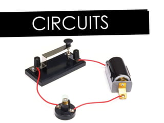
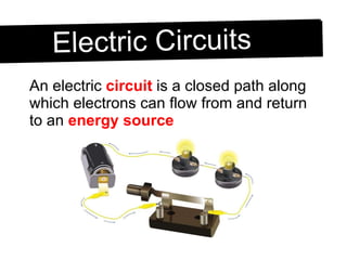
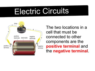
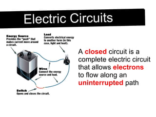
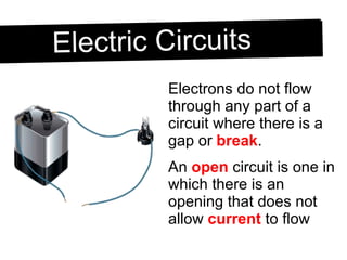
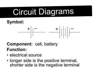
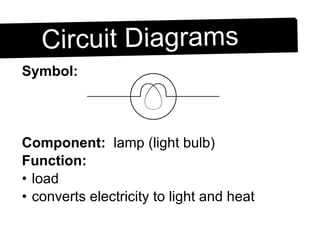
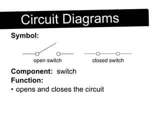
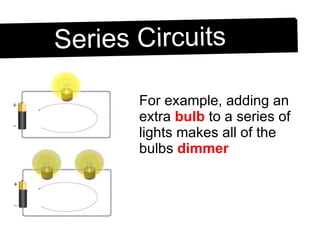
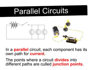
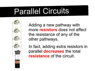
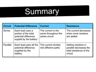
CIRCUITS
Electric Circuits An electric  circuit  is a closed path along which electrons can flow from and return to an  energy source
Electric Circuits The two locations in a cell that must be connected to other components are the  positive terminal  and the  negative terminal .
Electric Circuits A  closed  circuit is a complete electric circuit that allows  electrons  to flow along an  uninterrupted  path
Electric Circuits Electrons do not flow through any part of a circuit where there is a gap or  break . An  open  circuit is one in which there is an opening that does not allow  current  to flow
Electric Circuits For example, if a bulb is  loose  and does not make contact with the base of its socket, the circuit is  open  and the bulb will not  glow .
Electric Circuits A break in the  filament  of an  incandescent  bulb also creates an open circuit.  (This is the most common reason why a bulb doesn’t glow)
Electric Circuits A  switch  is a control device that can complete or break a circuit it is connected to. A switch is not  essential  for a circuit to operate, but it is usually included for convenience.
Circuit Diagrams Engineers and designers of electrical circuits use special  symbols  that show the components and connections in a circuit. These symbols make it easier to plan and  analyze  a circuit before you  build  it A drawing made with these symbols is called a  circuit diagram .
Circuit Diagrams Symbol: Component:   wire Function: conductor allows electrons to flow
Symbol: Component:   cell, battery Function: electrical source longer side is the positive terminal, shorter side is the negative terminal Circuit Diagrams
Symbol: Component:   lamp (light bulb) Function: load converts electricity to light and heat Circuit Diagrams
Symbol: Component:   general resistor/load Function: general load converts electricity to heat Circuit Diagrams
Symbol: Component:   switch Function: opens and closes the circuit Circuit Diagrams open switch closed switch
Symbol: Component:   ammeter Function: measures current through a device connected in series Circuit Diagrams
Symbol: Component:   voltmeter Function: measures voltage across a device connected in parallel Circuit Diagrams
A  series circuit  is an electric circuit that has only one path along which electrons can flow. If that pathway is  interrupted , the whole circuit cannot function Series Circuits
The amount of current is the  same  in all parts of a series circuit.  However, if you add more  resistors  you increase the total resistance of the circuit. Series Circuits
For example, adding an extra  bulb  to a series of lights makes all of the bulbs  dimmer Series Circuits
In a  parallel  circuit, each component has its own path for  current . The points where a circuit  divides  into different paths are culled  junction points .  Parallel Circuits
An interruption or  break  in one pathway does not affect the other  pathways  in the circuit.
Adding a new pathway with more  resistors  does not affect the resistance of any of the other pathways. In fact, adding extra resistors in parallel  decreases  the total  resistance  of the circuit. Parallel Circuits
This might seem counterintuitive, but think about how much less  resistance  there is when you drink with two straws instead of one Parallel Circuits
Summary Adding resistors in parallel decreases the total resistance of the circuit The current divides into different paths Each load uses all the potential difference supplied by the battery Parallel The current decreases when more resistors are added The current is the same throughout the series circuit Each load uses a portion of the total potential difference supplid by the battery Series Resistance Current Potential Difference Circuit

Circuits

  • 1.
  • 2.
    Electric Circuits Anelectric circuit is a closed path along which electrons can flow from and return to an energy source
  • 3.
    Electric Circuits Thetwo locations in a cell that must be connected to other components are the positive terminal and the negative terminal .
  • 4.
    Electric Circuits A closed circuit is a complete electric circuit that allows electrons to flow along an uninterrupted path
  • 5.
    Electric Circuits Electronsdo not flow through any part of a circuit where there is a gap or break . An open circuit is one in which there is an opening that does not allow current to flow
  • 6.
    Electric Circuits Forexample, if a bulb is loose and does not make contact with the base of its socket, the circuit is open and the bulb will not glow .
  • 7.
    Electric Circuits Abreak in the filament of an incandescent bulb also creates an open circuit. (This is the most common reason why a bulb doesn’t glow)
  • 8.
    Electric Circuits A switch is a control device that can complete or break a circuit it is connected to. A switch is not essential for a circuit to operate, but it is usually included for convenience.
  • 9.
    Circuit Diagrams Engineersand designers of electrical circuits use special symbols that show the components and connections in a circuit. These symbols make it easier to plan and analyze a circuit before you build it A drawing made with these symbols is called a circuit diagram .
  • 10.
    Circuit Diagrams Symbol:Component: wire Function: conductor allows electrons to flow
  • 11.
    Symbol: Component: cell, battery Function: electrical source longer side is the positive terminal, shorter side is the negative terminal Circuit Diagrams
  • 12.
    Symbol: Component: lamp (light bulb) Function: load converts electricity to light and heat Circuit Diagrams
  • 13.
    Symbol: Component: general resistor/load Function: general load converts electricity to heat Circuit Diagrams
  • 14.
    Symbol: Component: switch Function: opens and closes the circuit Circuit Diagrams open switch closed switch
  • 15.
    Symbol: Component: ammeter Function: measures current through a device connected in series Circuit Diagrams
  • 16.
    Symbol: Component: voltmeter Function: measures voltage across a device connected in parallel Circuit Diagrams
  • 17.
    A seriescircuit is an electric circuit that has only one path along which electrons can flow. If that pathway is interrupted , the whole circuit cannot function Series Circuits
  • 18.
    The amount ofcurrent is the same in all parts of a series circuit. However, if you add more resistors you increase the total resistance of the circuit. Series Circuits
  • 19.
    For example, addingan extra bulb to a series of lights makes all of the bulbs dimmer Series Circuits
  • 20.
    In a parallel circuit, each component has its own path for current . The points where a circuit divides into different paths are culled junction points . Parallel Circuits
  • 21.
    An interruption or break in one pathway does not affect the other pathways in the circuit.
  • 22.
    Adding a newpathway with more resistors does not affect the resistance of any of the other pathways. In fact, adding extra resistors in parallel decreases the total resistance of the circuit. Parallel Circuits
  • 23.
    This might seemcounterintuitive, but think about how much less resistance there is when you drink with two straws instead of one Parallel Circuits
  • 24.
    Summary Adding resistorsin parallel decreases the total resistance of the circuit The current divides into different paths Each load uses all the potential difference supplied by the battery Parallel The current decreases when more resistors are added The current is the same throughout the series circuit Each load uses a portion of the total potential difference supplid by the battery Series Resistance Current Potential Difference Circuit