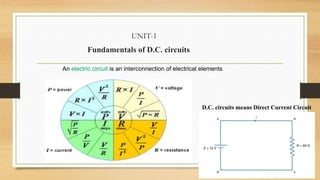
The document provides an overview of direct current (DC) circuits and some key concepts including:
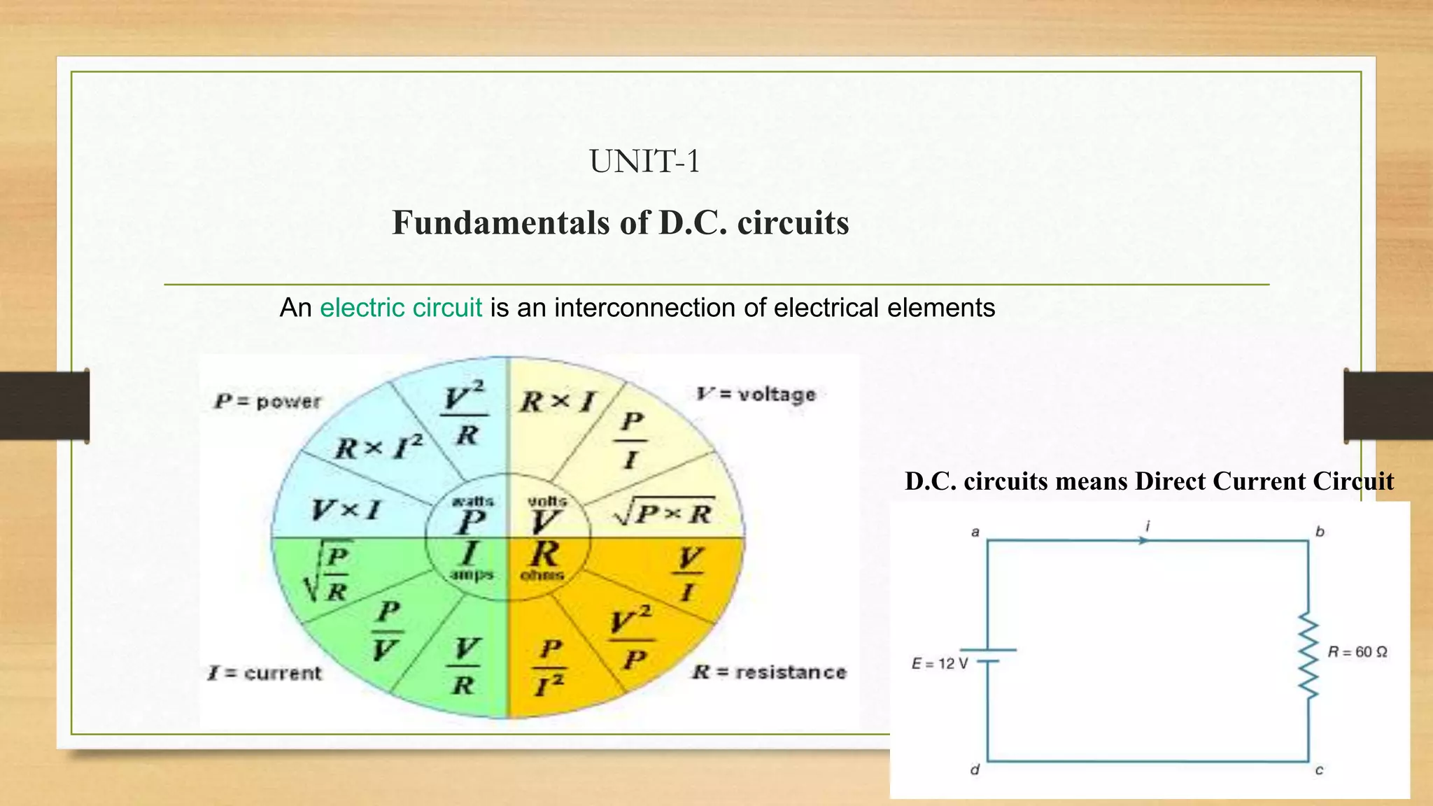
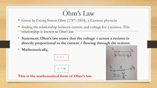
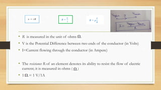
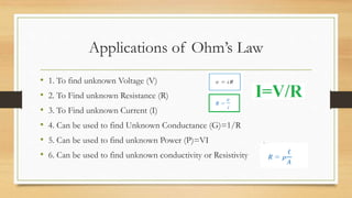
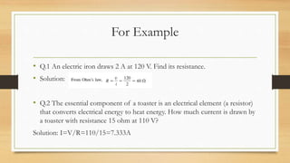
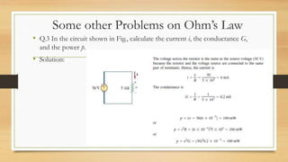
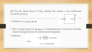
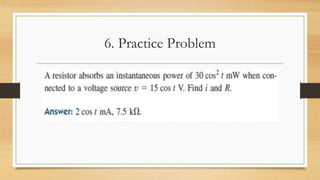
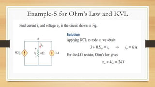
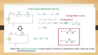
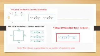
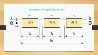
1. Ohm's law defines the relationship between voltage, current, and resistance in a circuit. It states that voltage is directly proportional to current.
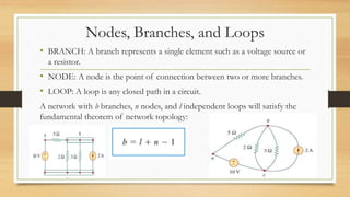
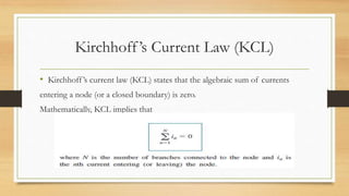
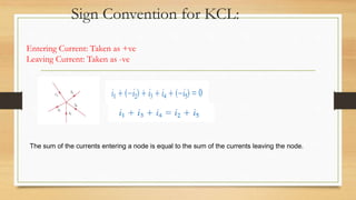
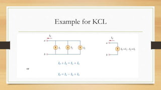
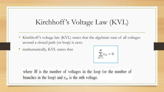
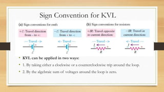
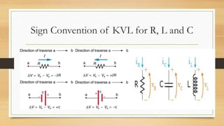
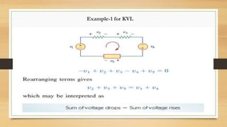
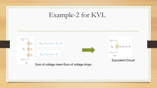
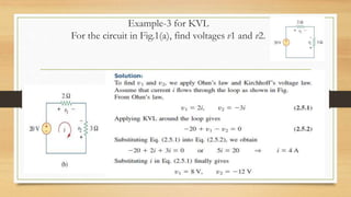
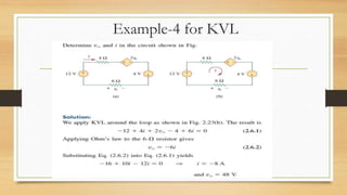
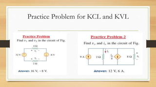
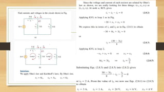
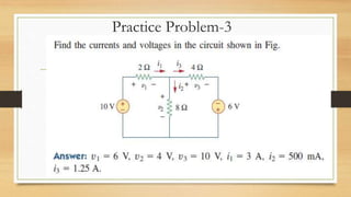
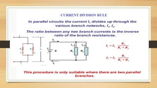
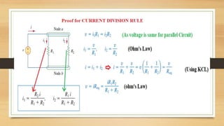
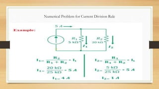
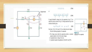
2. Kirchhoff's laws (KCL and KVL) are important circuit analysis tools. KCL states the algebraic sum of currents at a node is zero. KVL states the algebraic sum of voltages in a closed loop is zero.
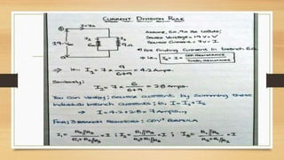
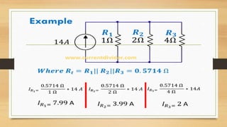
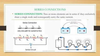
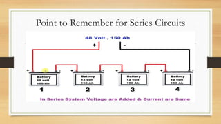
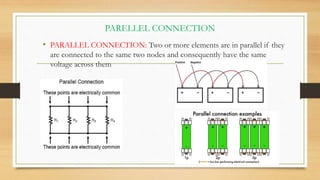
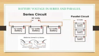
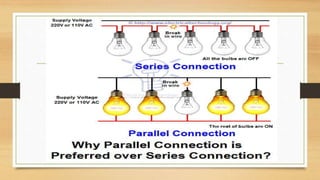
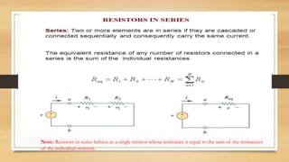
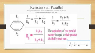
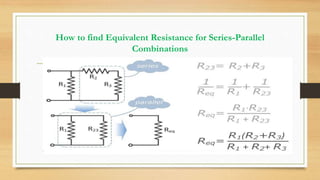
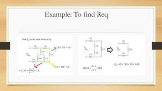
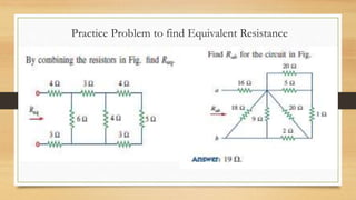
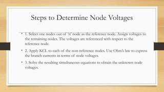
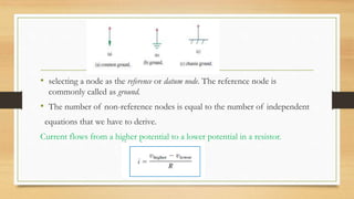
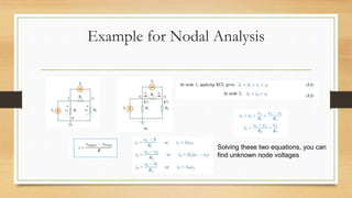
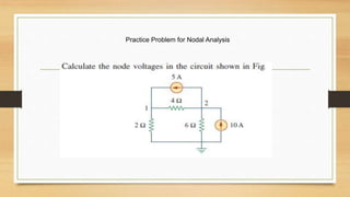
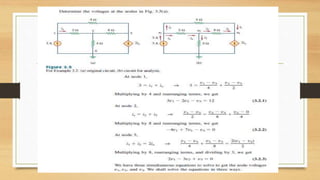
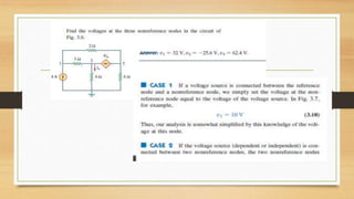
3. Circuits can have components connected in series, parallel, or a combination. Nodal analysis uses KCL and Ohm's law to set up equations to solve for unknown node voltages in a circuit.