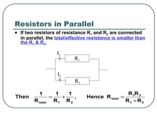
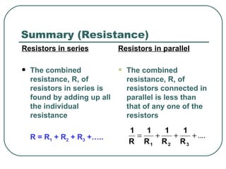
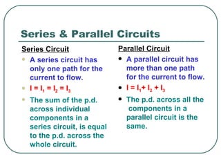
This document discusses series and parallel circuits. It defines series and parallel circuits and explains how to calculate total resistance and current in each. In series circuits, total resistance is the sum of individual resistances and current is the same everywhere. In parallel circuits, total resistance is less than individual resistances and total current is the sum of branch currents. The document also provides examples of calculating resistance, current, and voltage in series and parallel circuit problems.


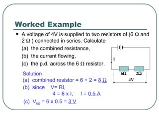
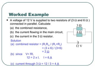
![Worked Example The battery in the circuit illustrated has an e.m.f. of 16 V and negligible internal resistance. Calculate (a) the combined resistance, (b) the current flowing through the 8 resistor. Solution (a) combined resistor = [(R 1 R 2) / (R 1 +R 2 )] + R 3 = [(36x18) / (36+18)] + 8 = 20 (b) since V= RI, 16 = 20 x I, I = 0.8 A hence, current through 8 resistor is 0.8 A R2 R1 R3 16V 8 36 18 ](https://image.slidesharecdn.com/4electriccircuitsamended-100501235857-phpapp02/85/Electric-Circuits-Ppt-Slides-28-320.jpg)