Downloaded 202 times
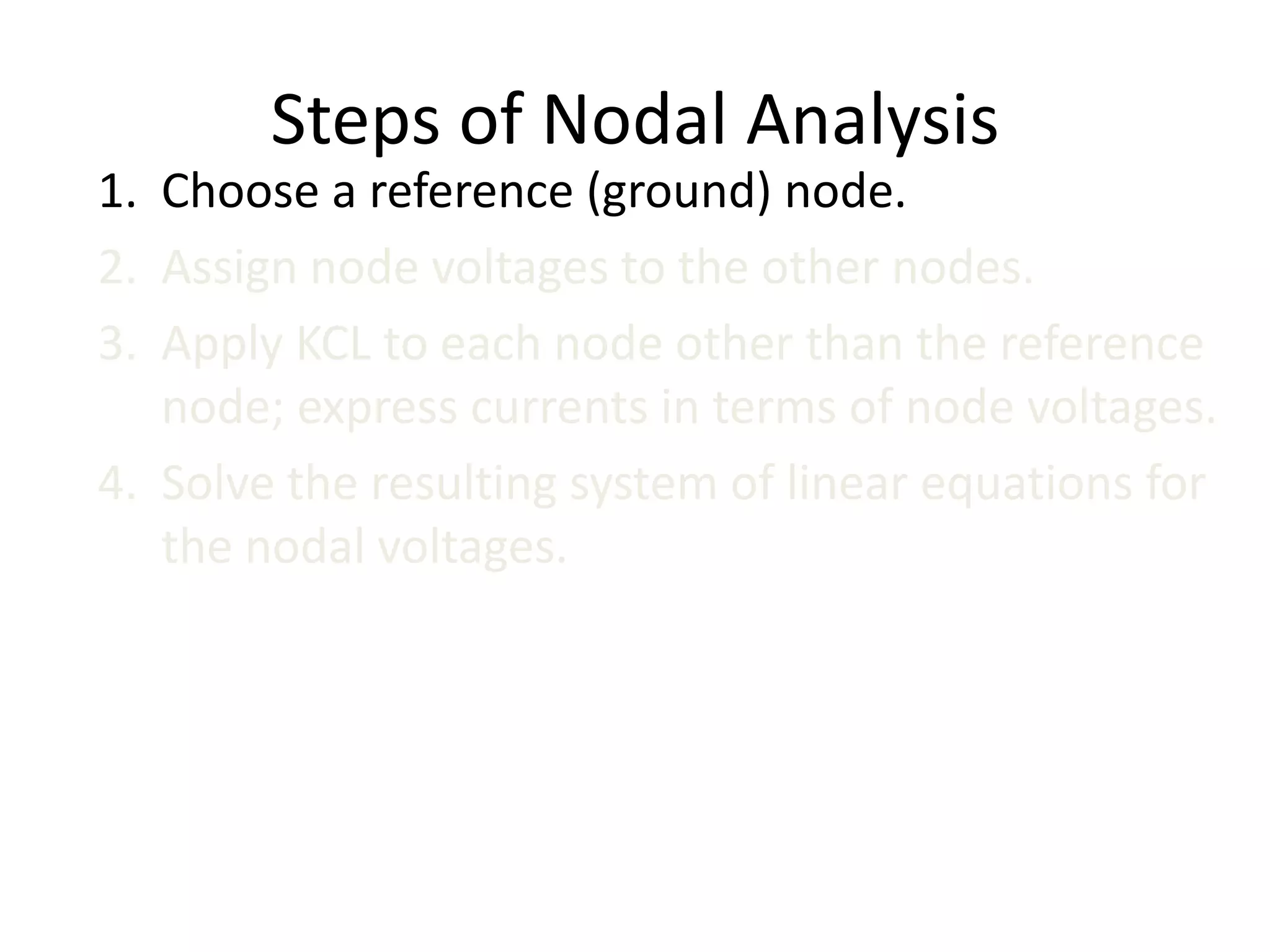
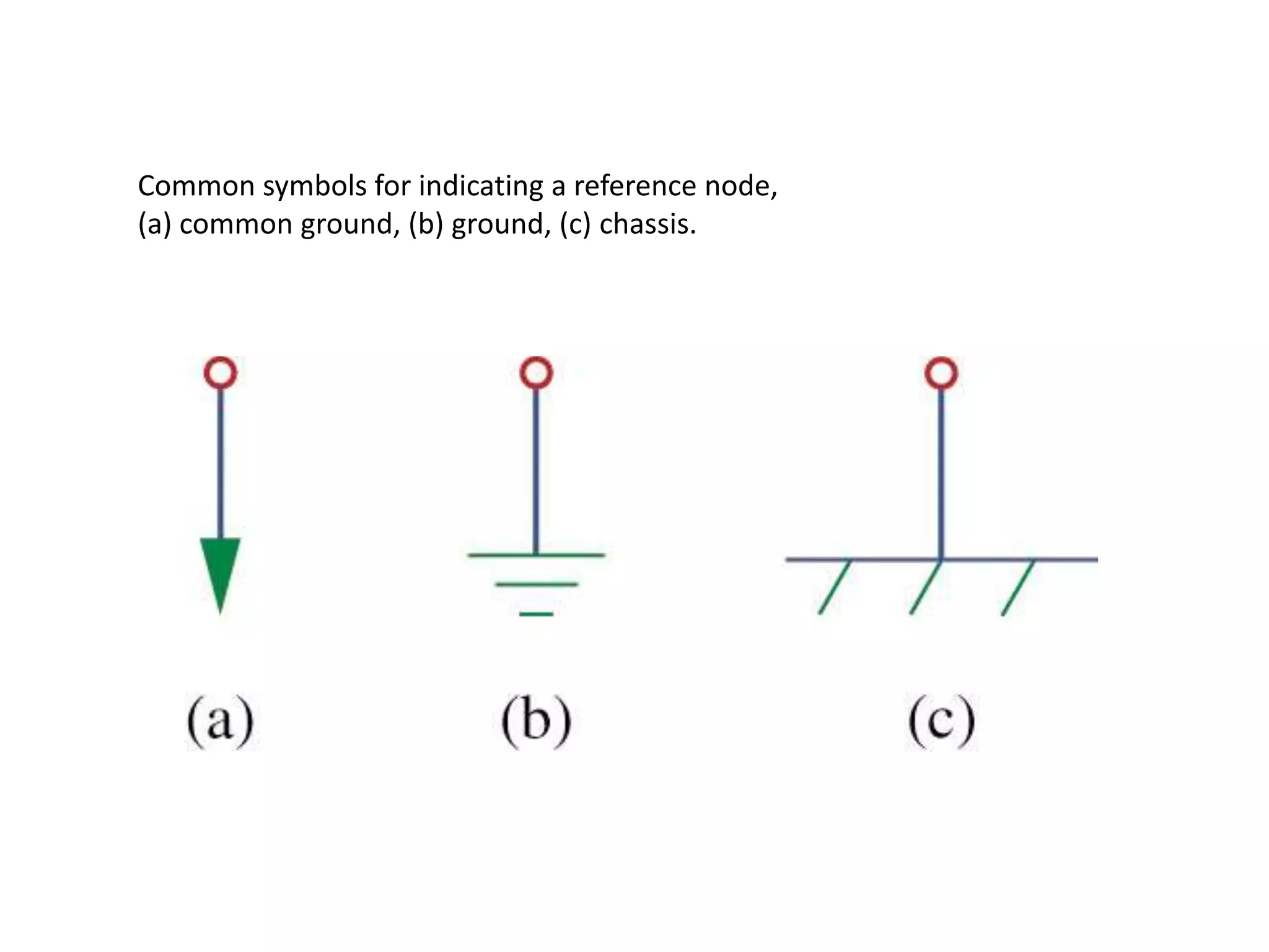
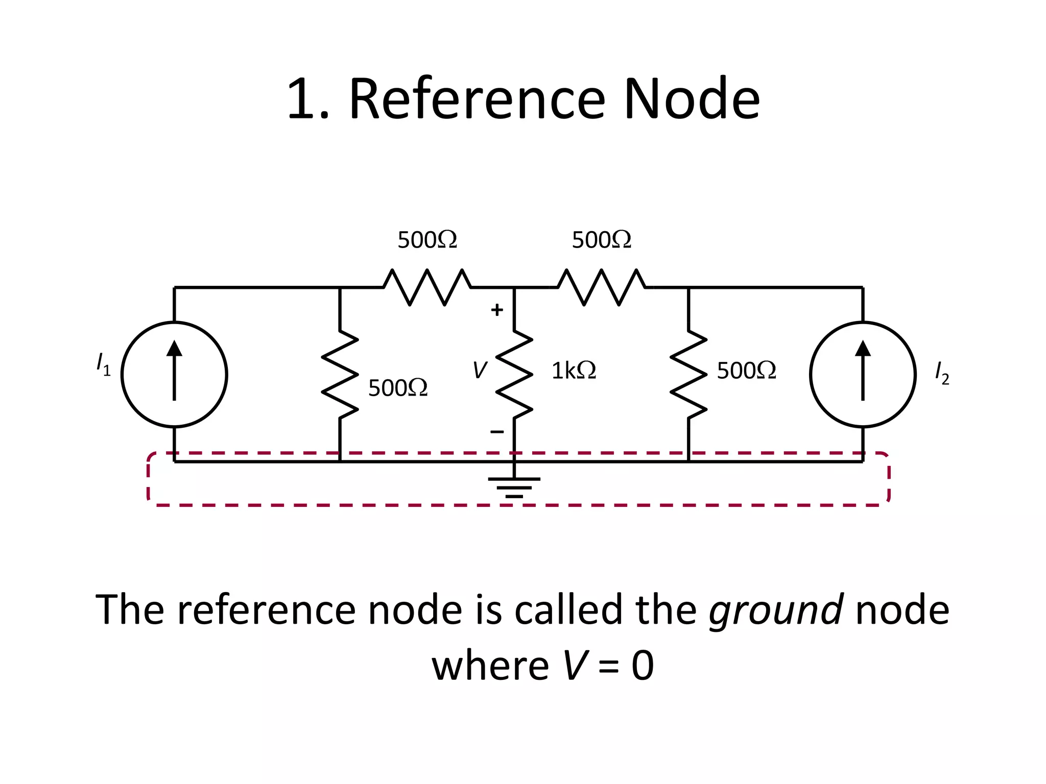
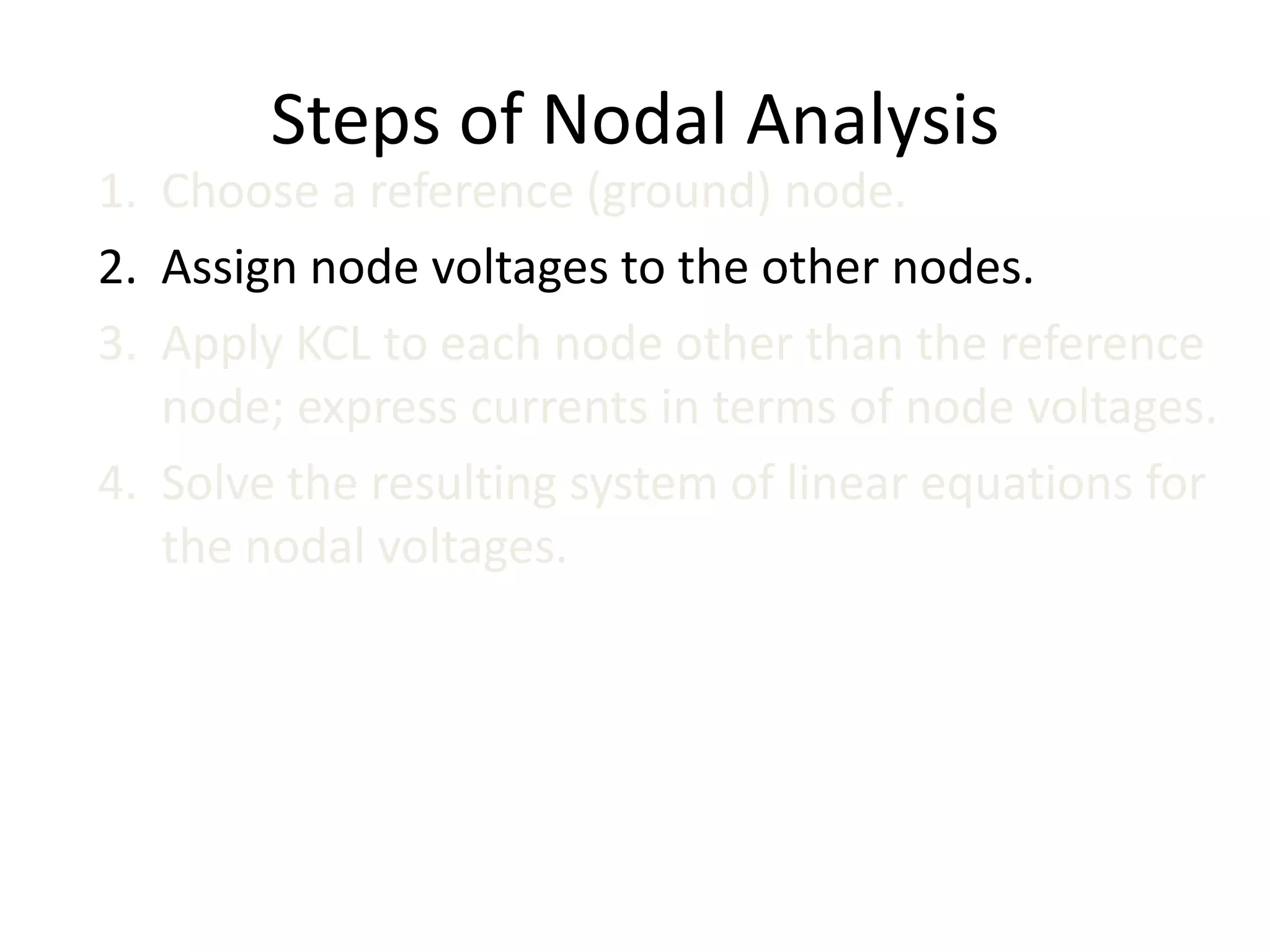
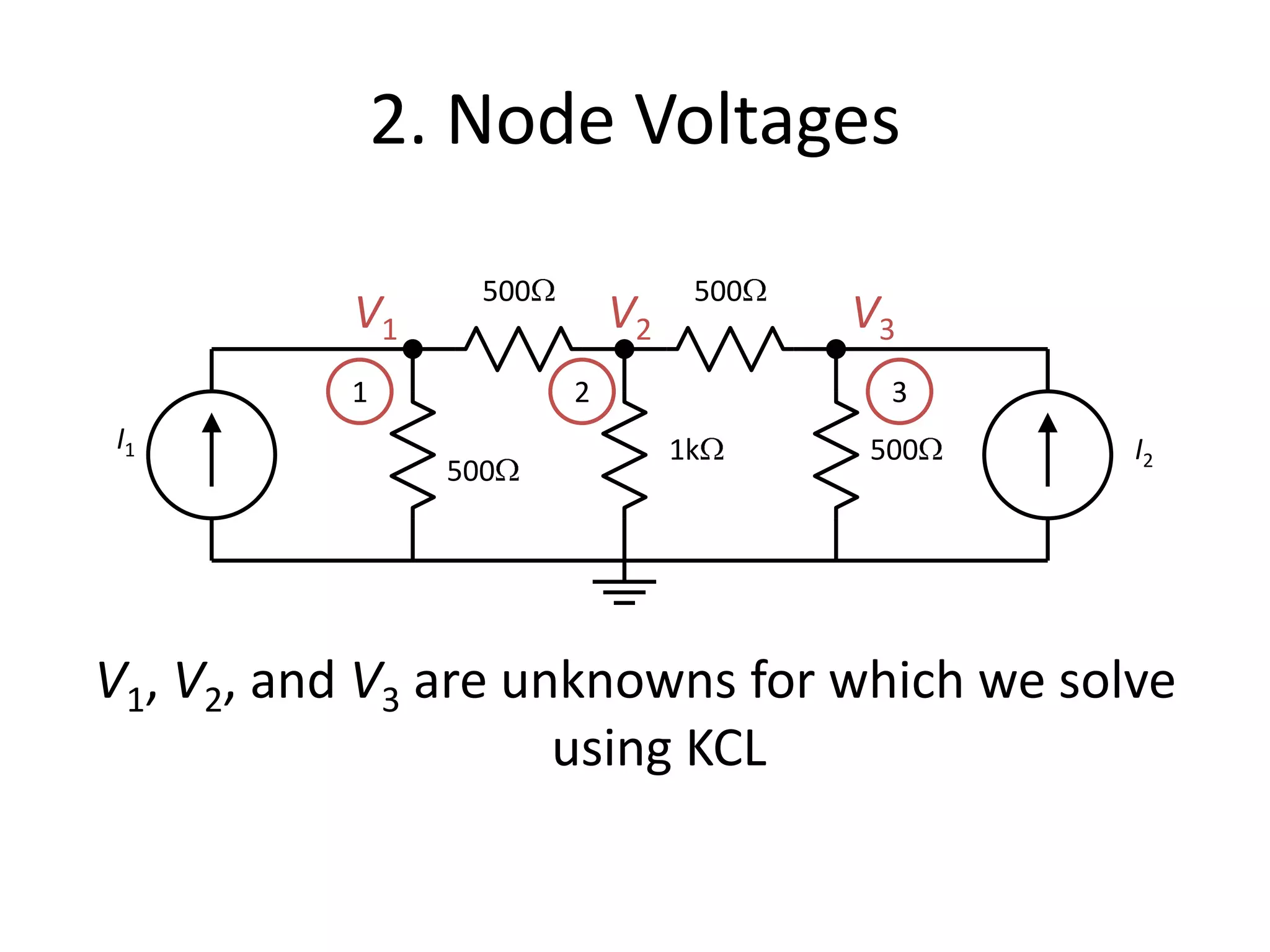
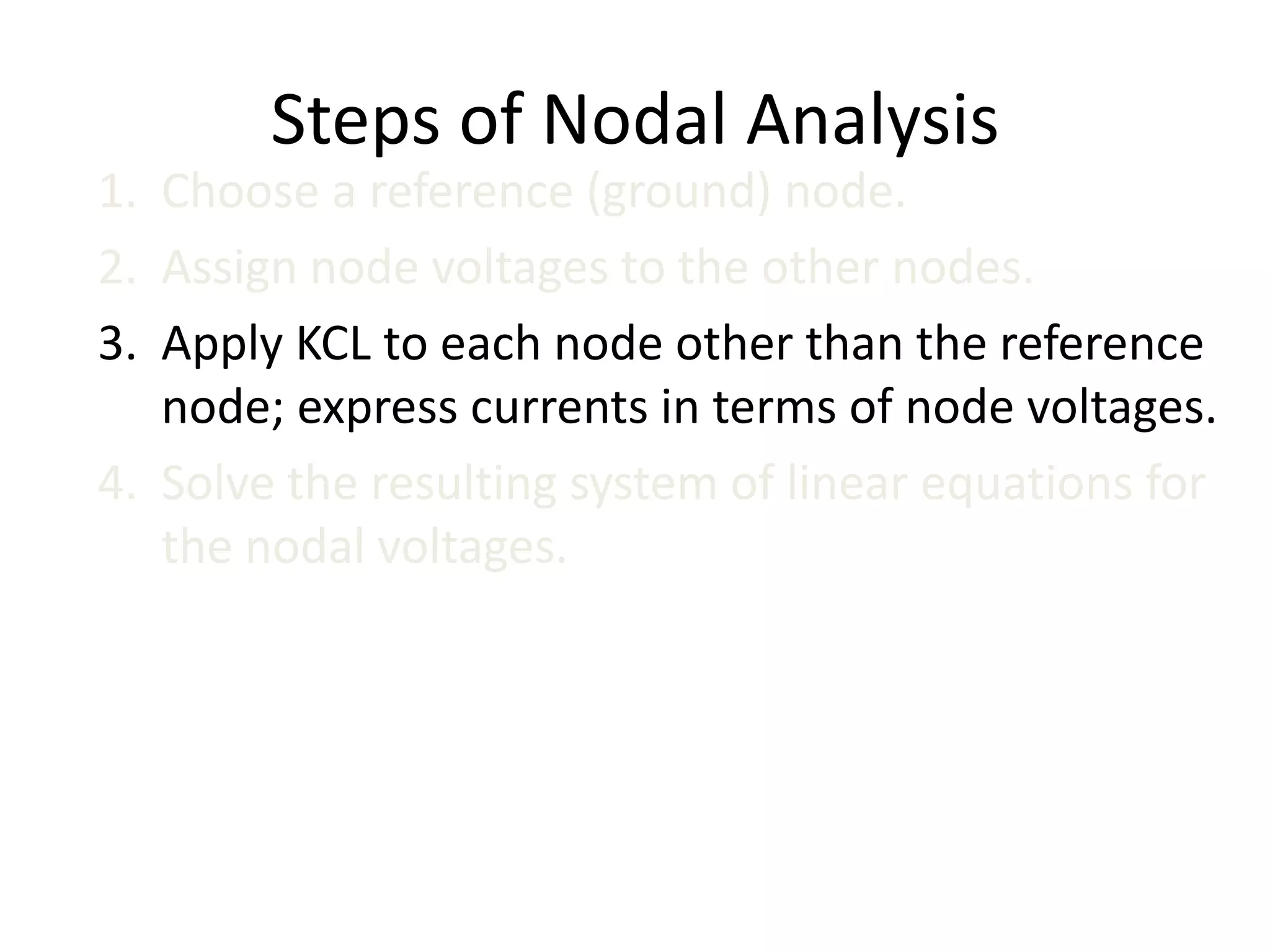
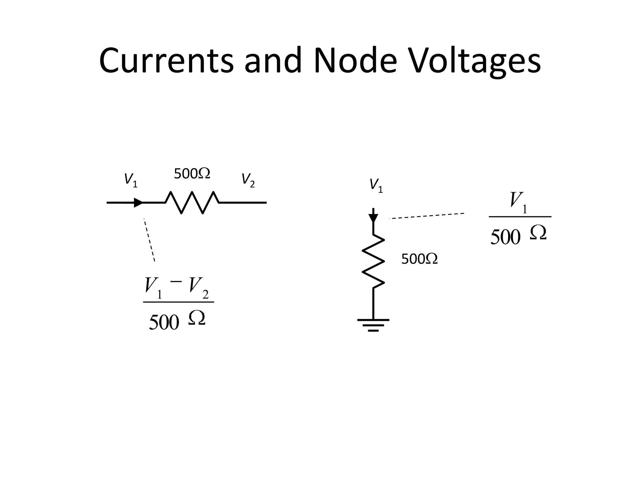
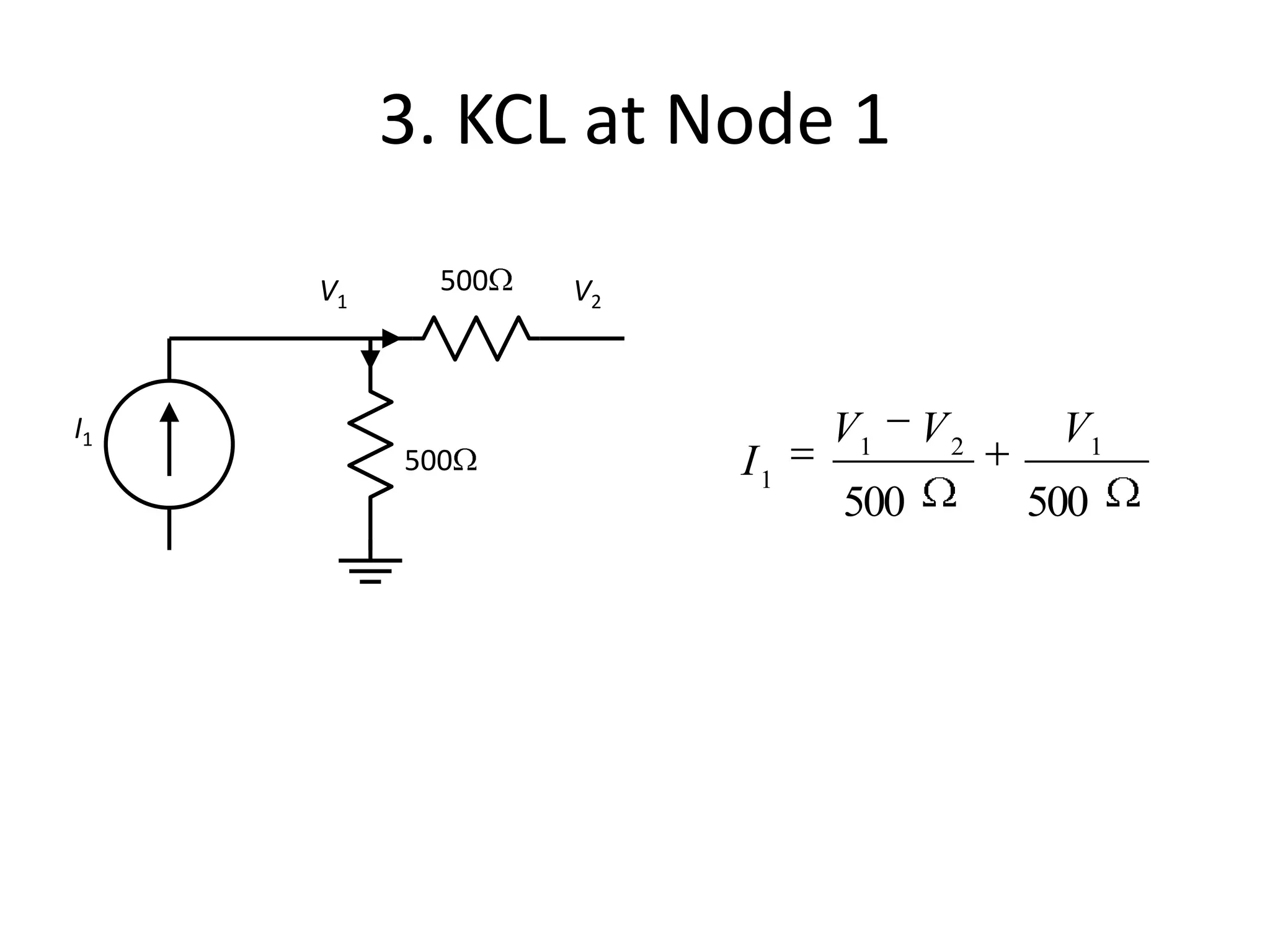
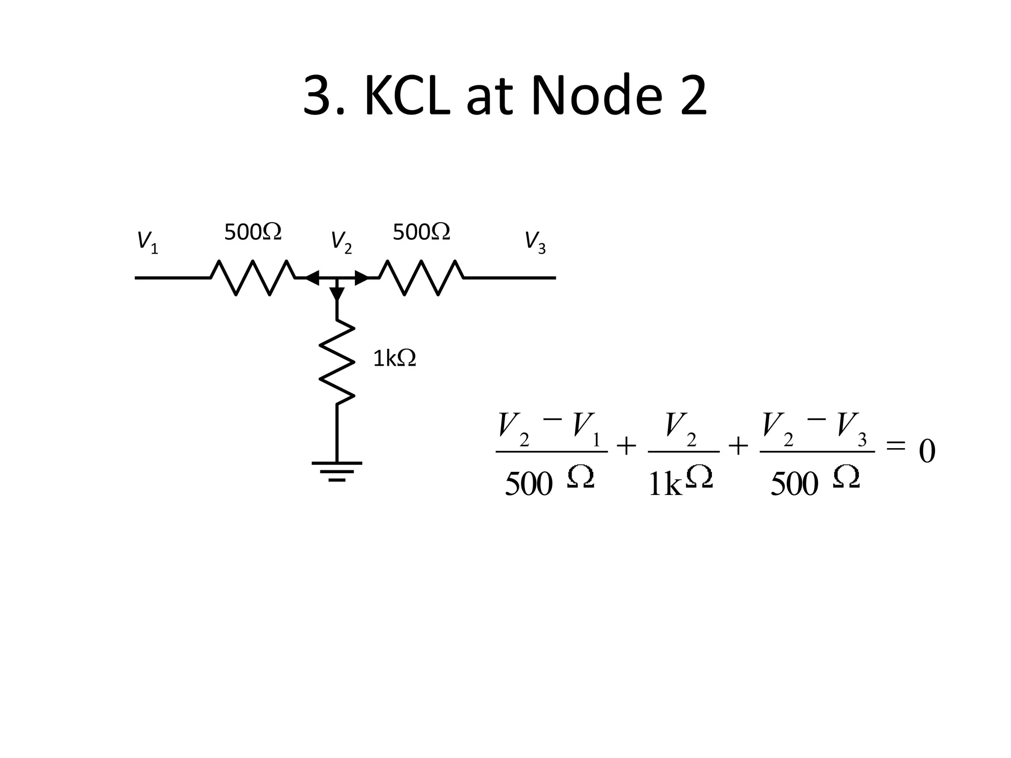
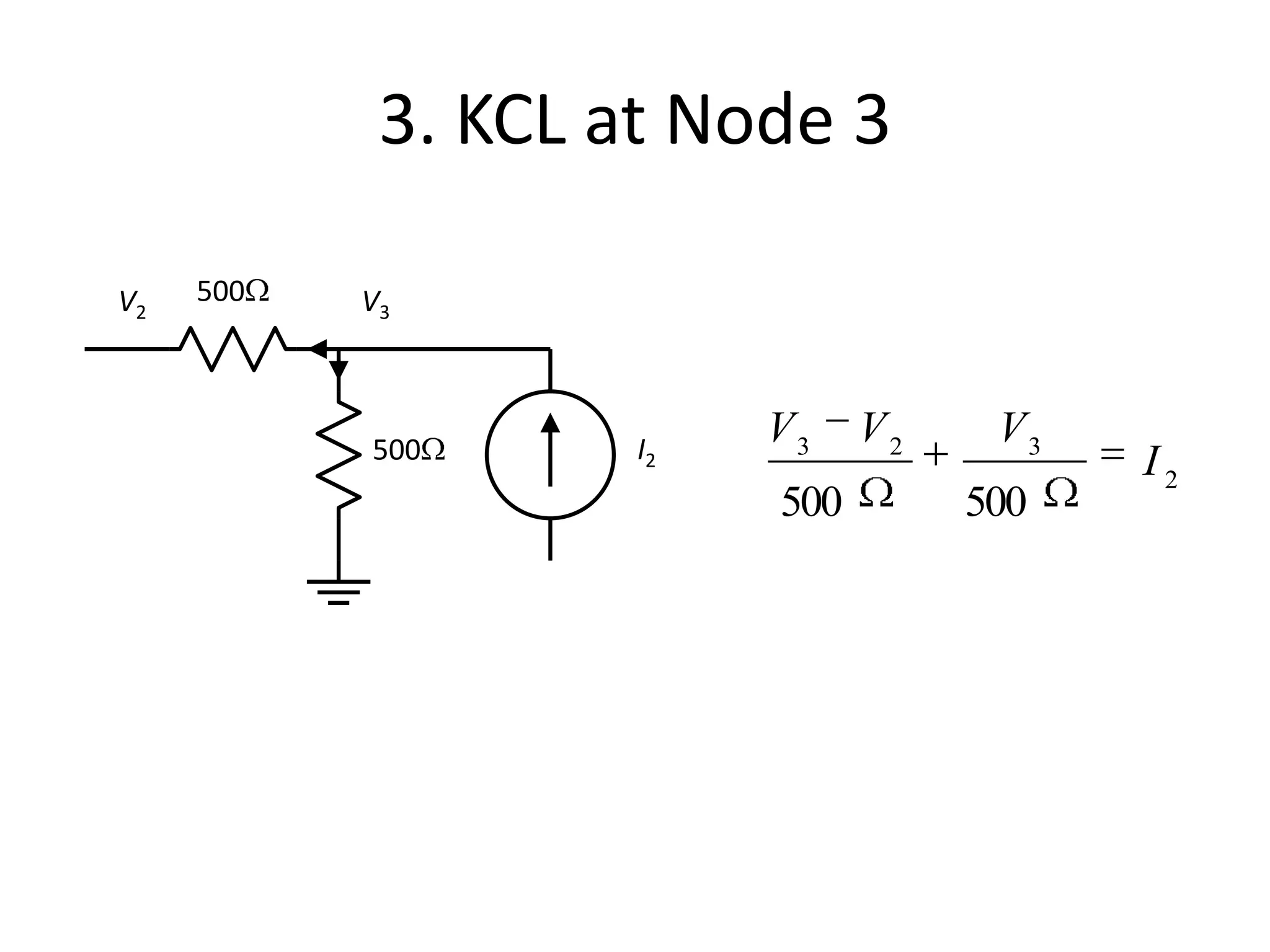
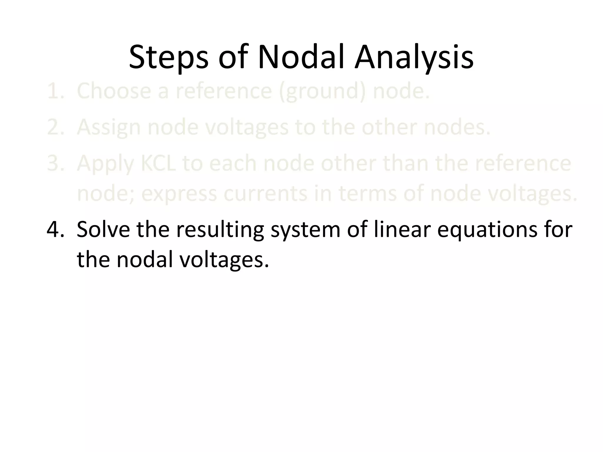
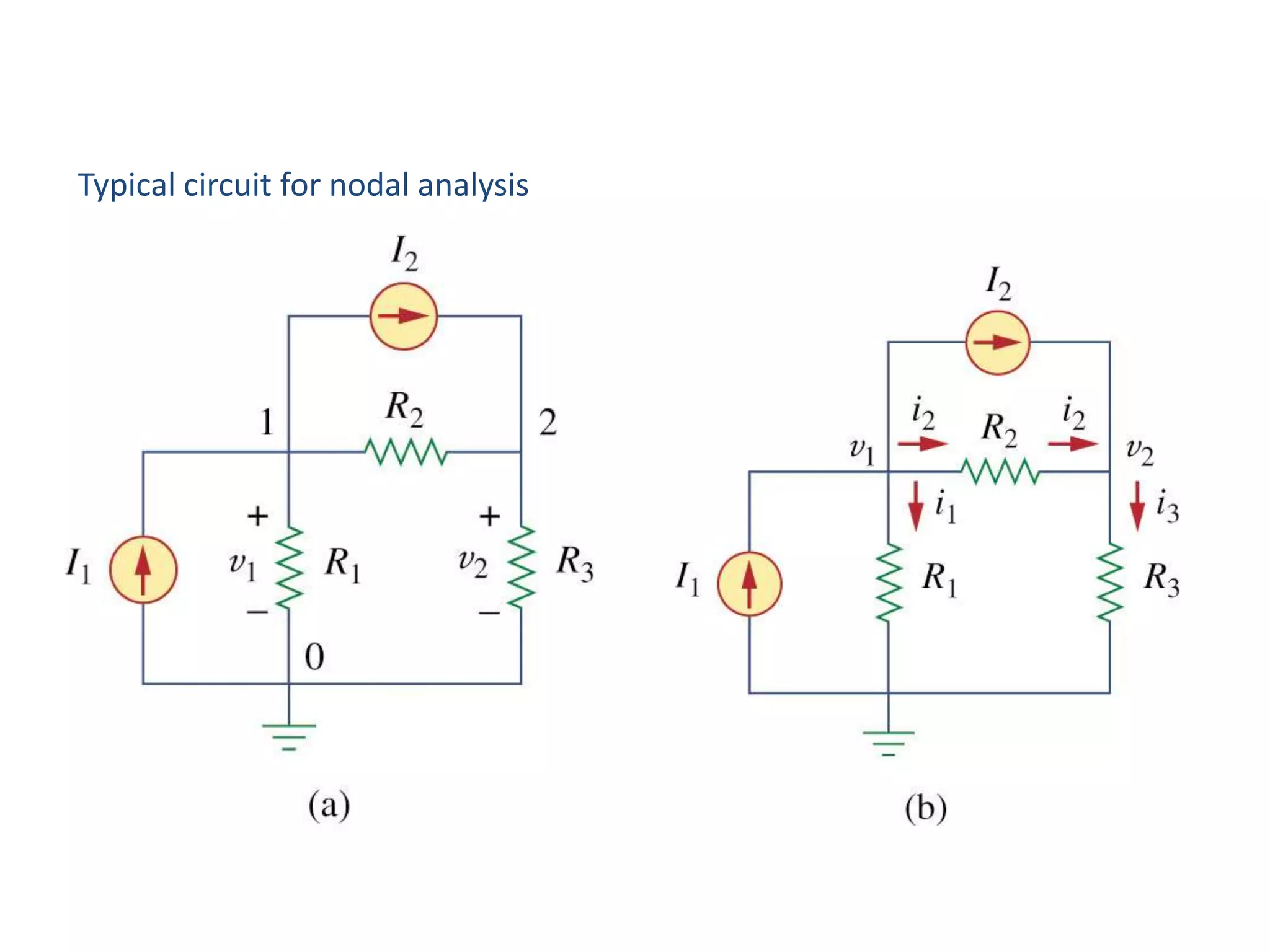
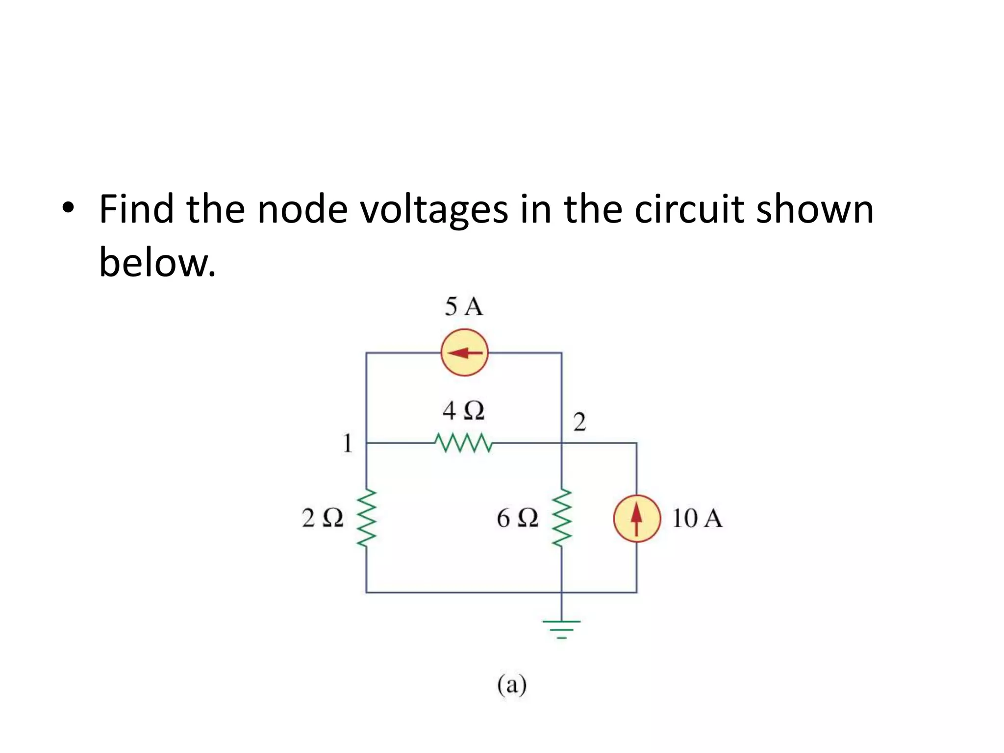
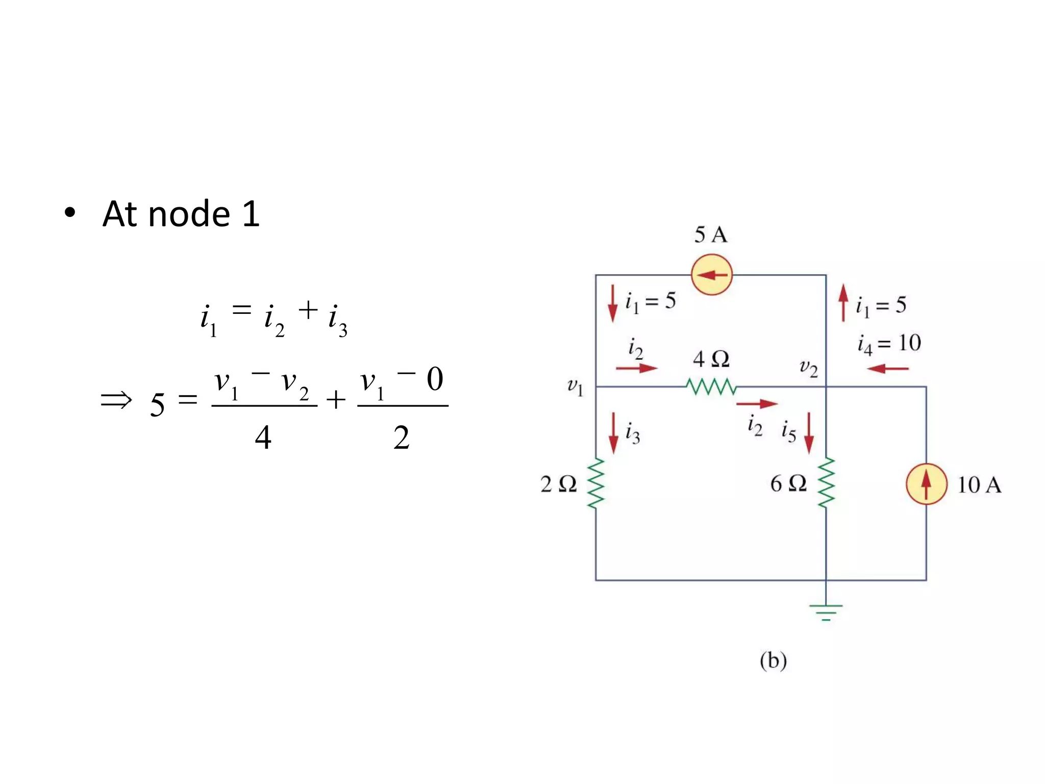
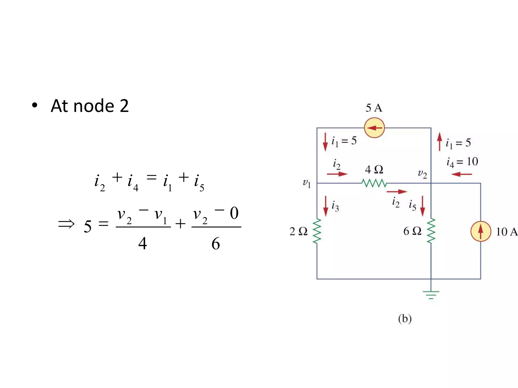
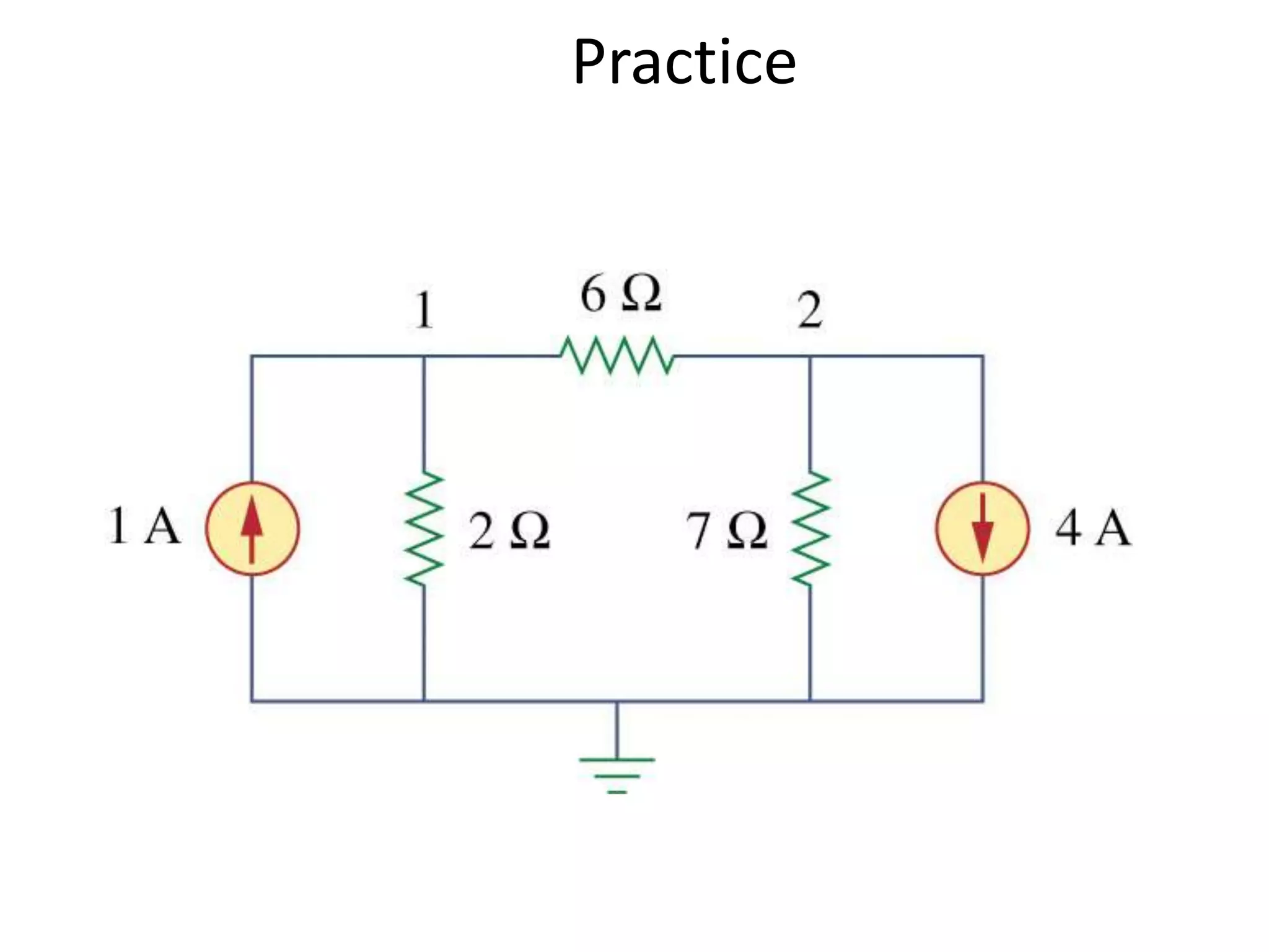
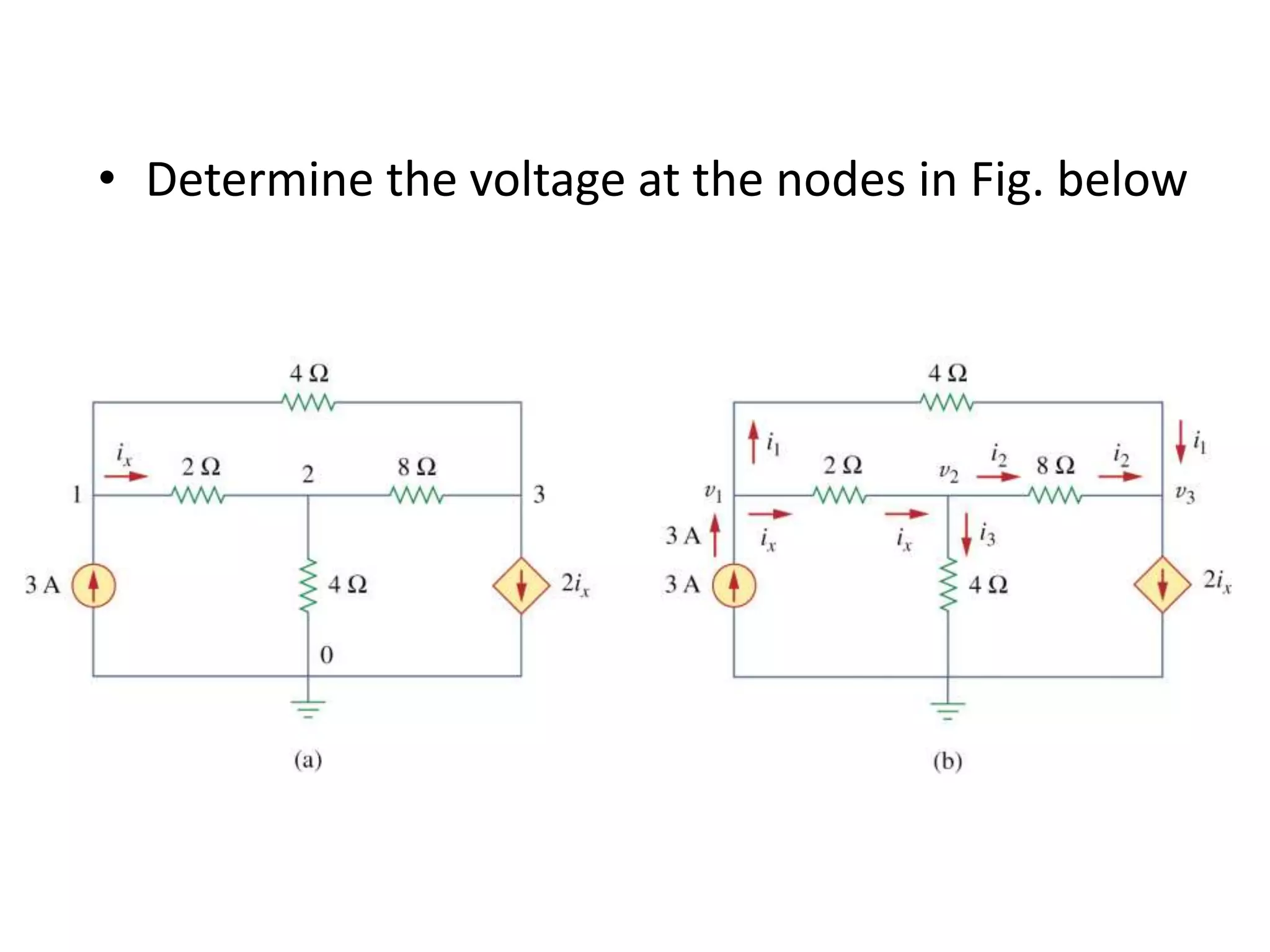
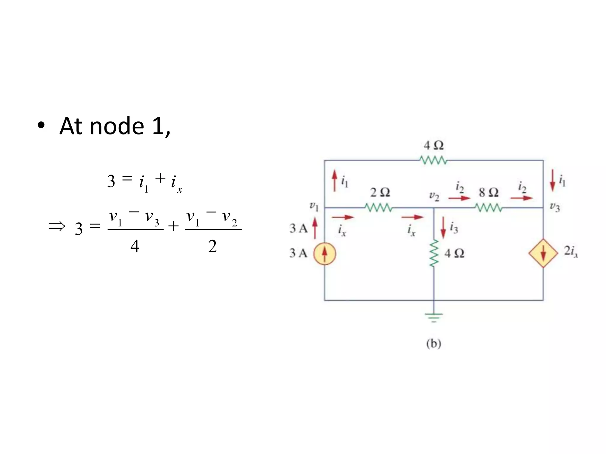
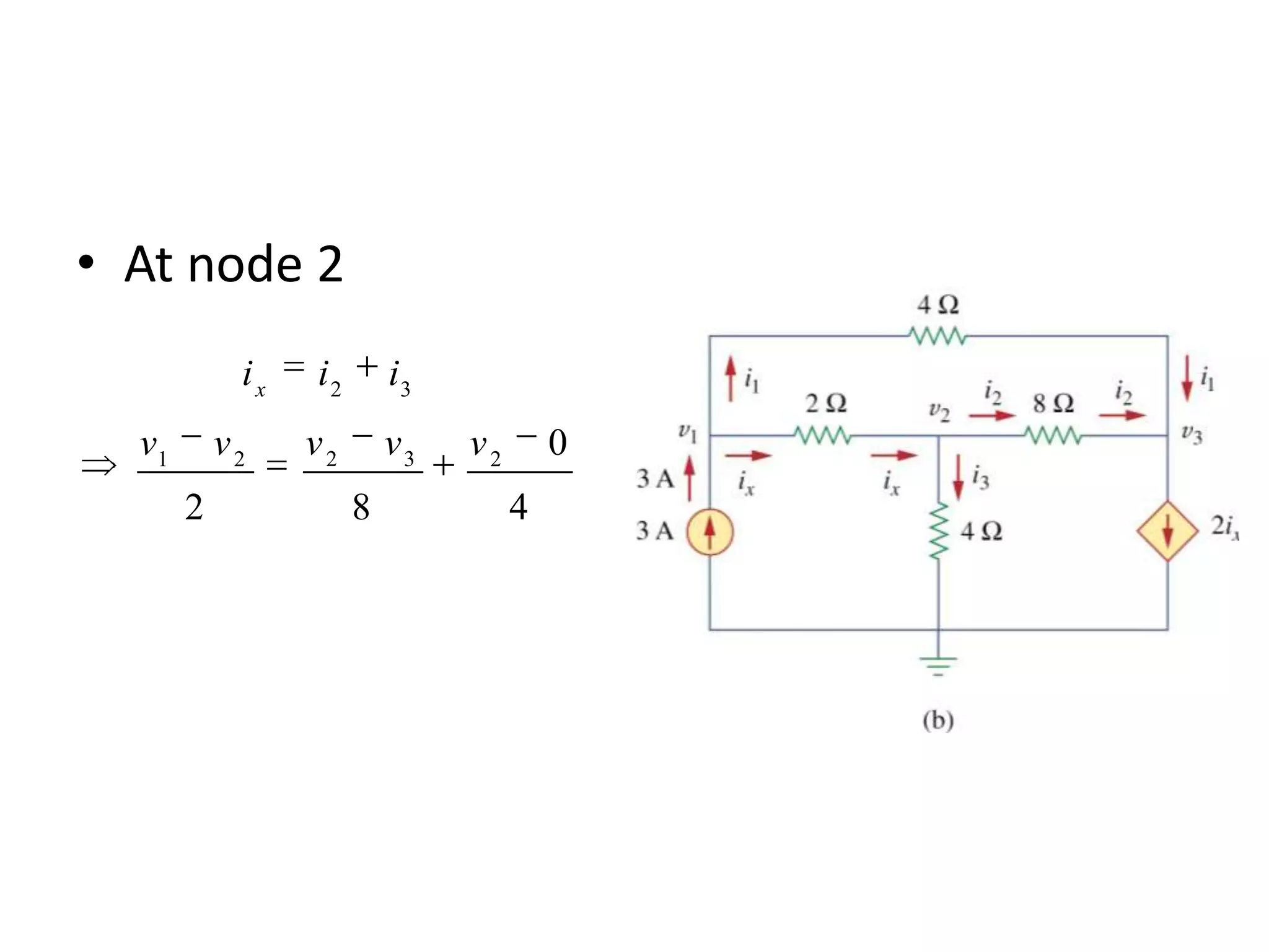
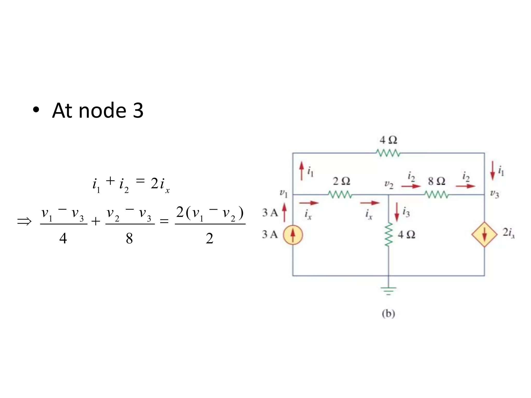
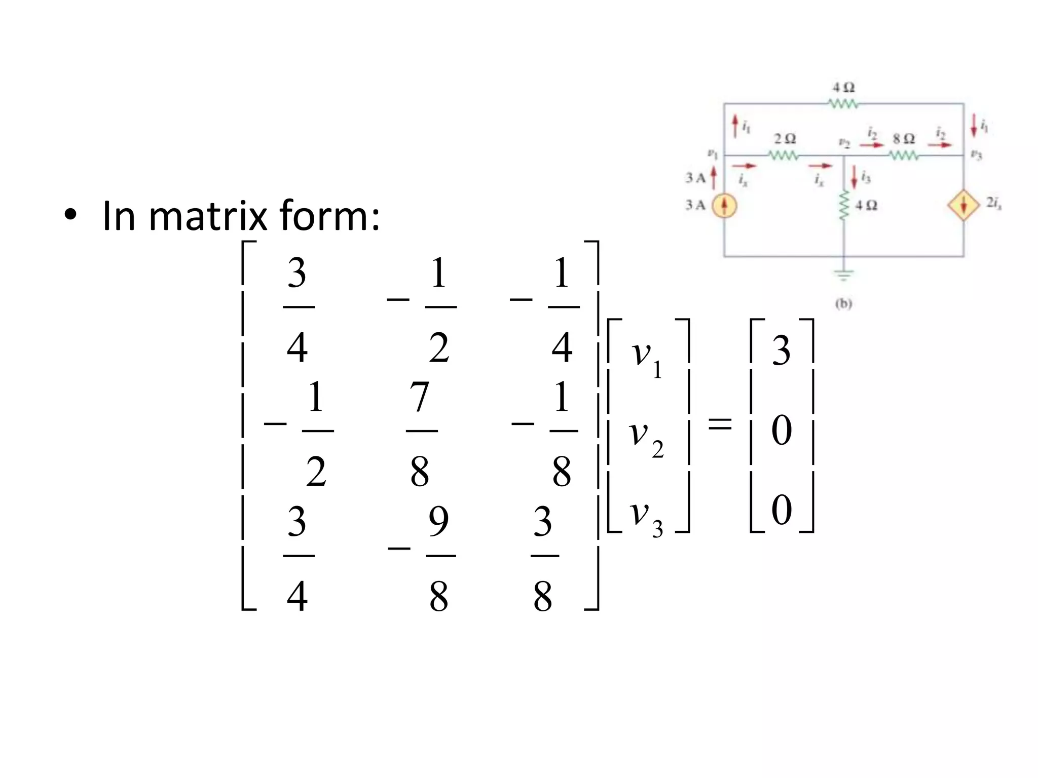
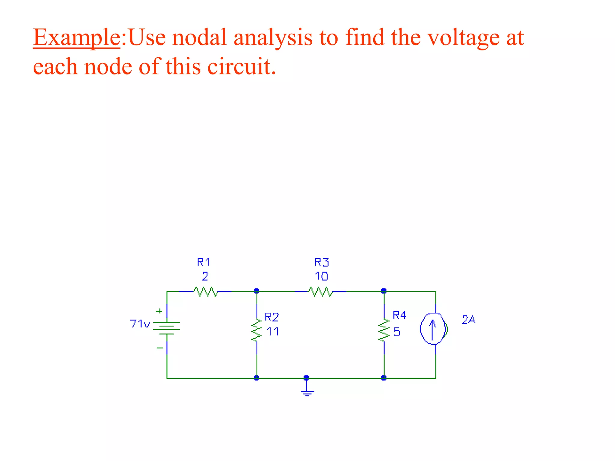
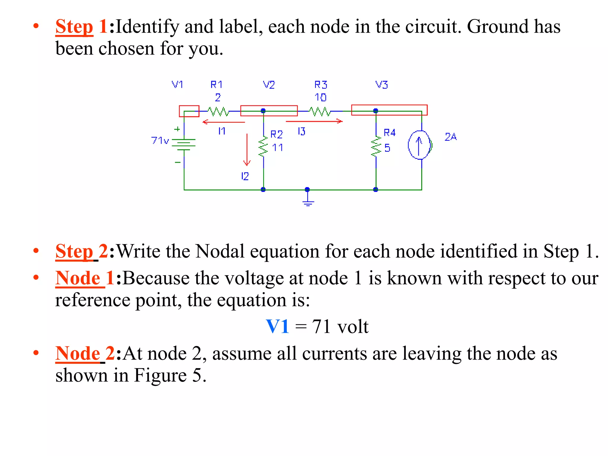
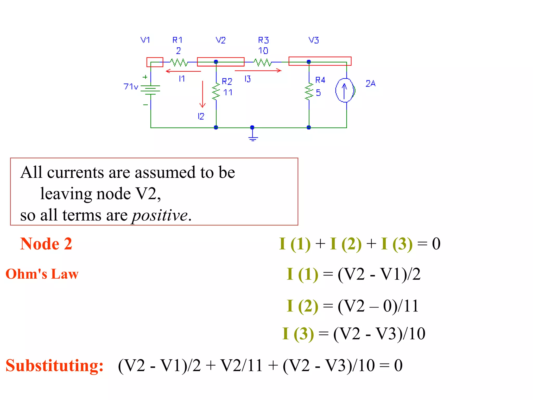
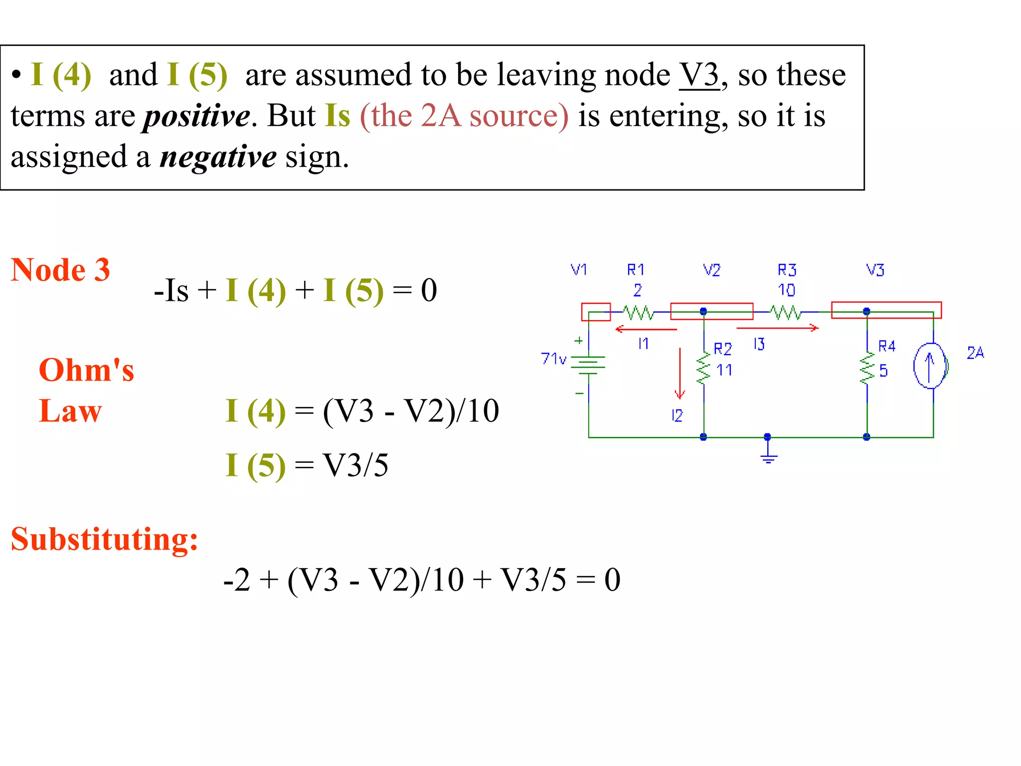
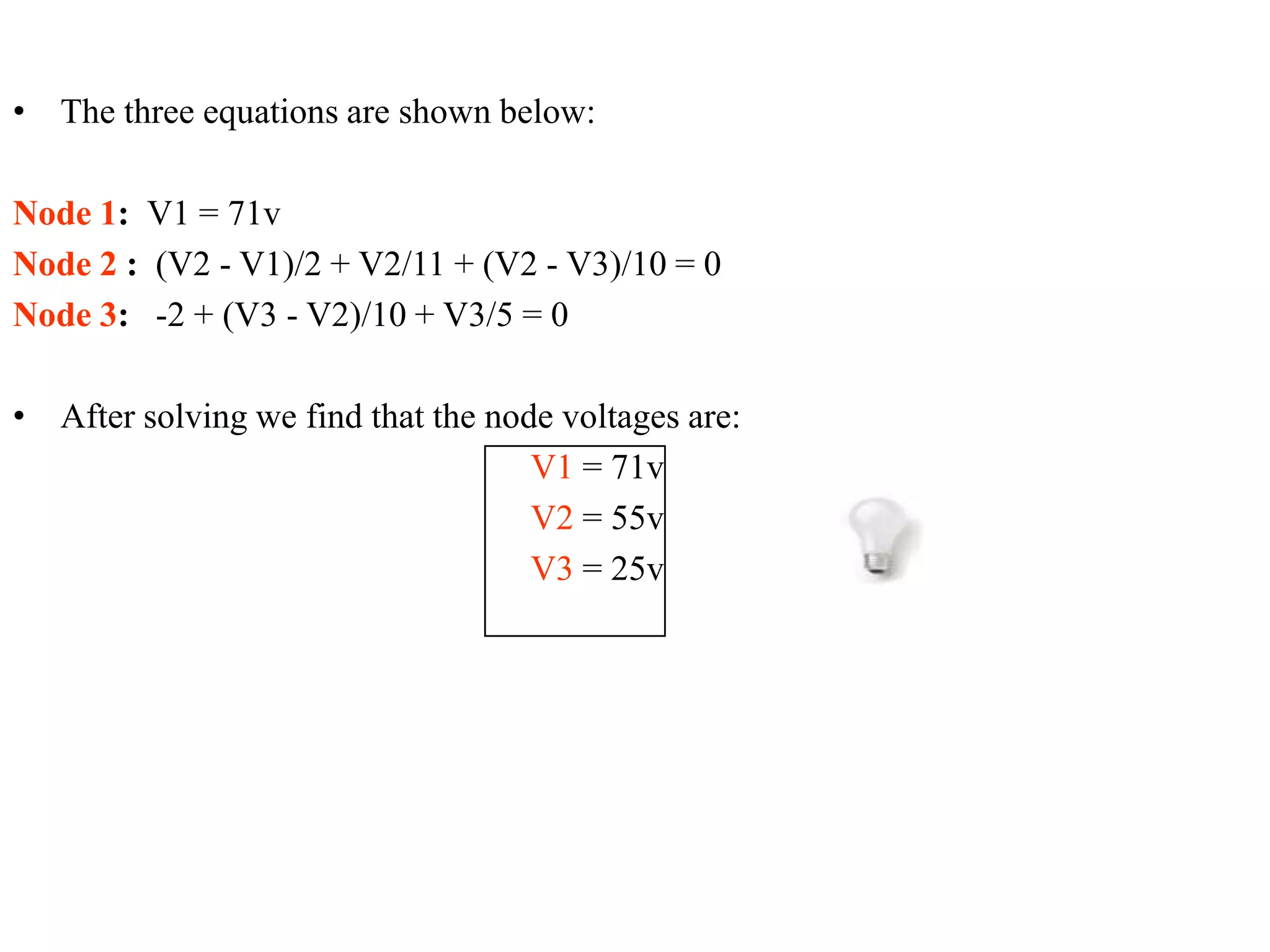
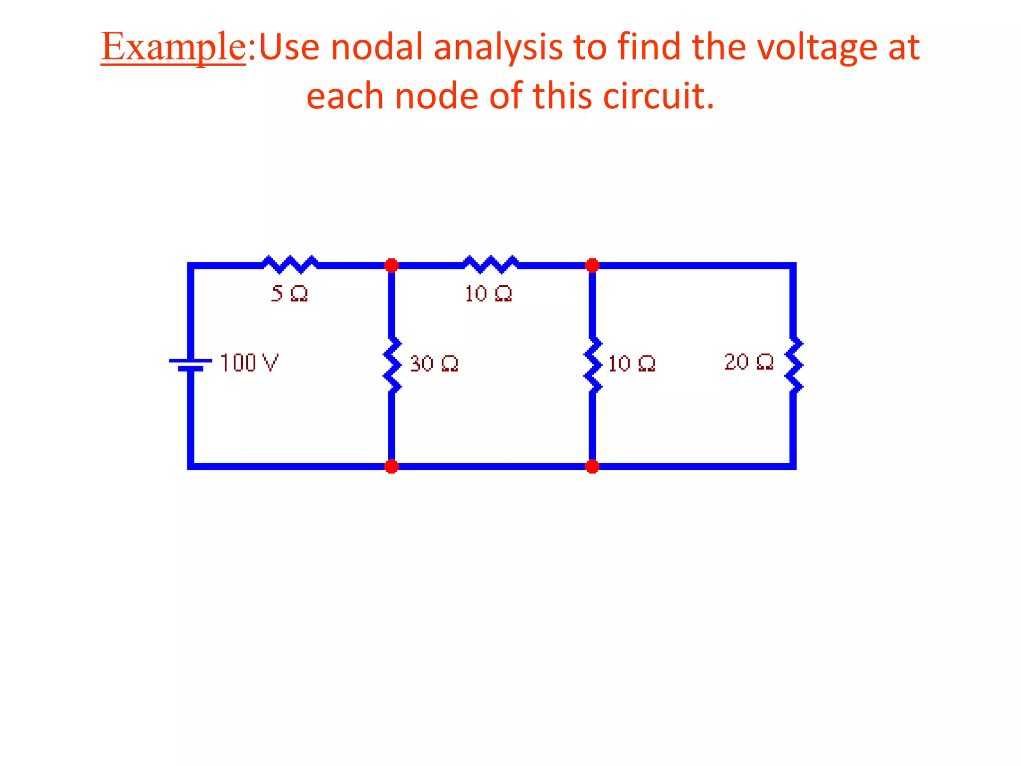

The document discusses nodal analysis for solving electric circuits. It explains the steps of nodal analysis which are: 1) choose a reference node, 2) assign voltages to each node, 3) apply Kirchhoff's Current Law at each node to write equations relating the currents and voltages, 4) solve the resulting system of equations. It provides an example circuit and writes out the nodal equations at each node to solve for the unknown node voltages.


![Circuit Network Analysis - [Chapter4] Laplace Transform](https://cdn.slidesharecdn.com/ss_thumbnails/ch4-150613063858-lva1-app6891-thumbnail.jpg?width=640&height=640&fit=bounds)


![Coded Agents – with UiPath SDK + LangGraph [Virtual Hands-on Workshop]](https://cdn.slidesharecdn.com/ss_thumbnails/codedagentsdeck-251215155422-5497c599-thumbnail.jpg?width=640&height=640&fit=bounds)


