Downloaded 207 times

![Leq for Inductors in Parallel
i
( ) ( ) ( ) ( )[ ] 1
4321eq
t
t
t
t4
t
t3
t
t2
t
t1
t
t4
4
t
t3
3
t
t2
2
t
t1
1
4321
1111L
vdt
1
vdt
1
vdt
1
vdt
1
vdt
1
vdt
1
vdt
1
vdt
1
vdt
1
1
o
1
o
1
o
1
o
1
o
1
o
1
o
1
o
1
o
−
+++=
=
+++=
==
==
+++=
∫
∫∫∫∫
∫∫
∫∫
LLLL
L
i
LLLL
i
L
i
L
i
L
i
L
i
iiiii
eq
in
in
in
achdesign.info@gmail.com](https://image.slidesharecdn.com/inductors-180212153926/85/Inductors-18-320.jpg)
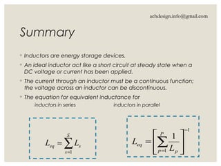


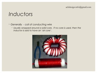
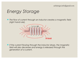
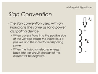
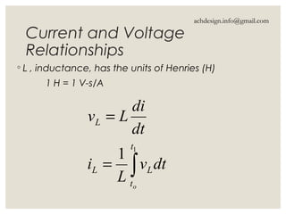
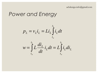
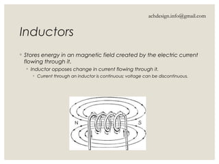
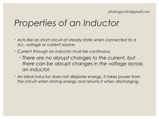
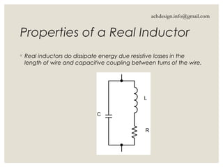
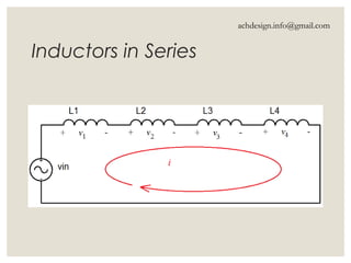
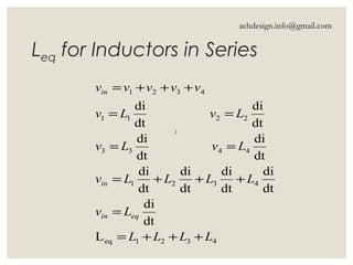
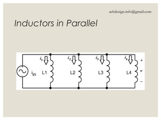
Inductors are energy storage devices that store energy in a magnetic field generated by an electric current and oppose changes in current flow. They can act like short circuits at steady state with DC sources, and their current must be continuous while voltage can be discontinuous. The document also details calculations for inductance in series and parallel configurations.