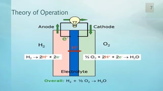
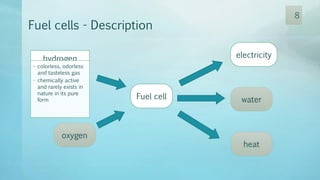
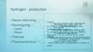
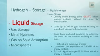
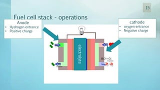
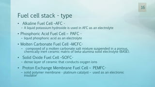
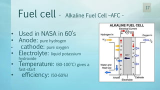
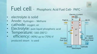
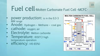
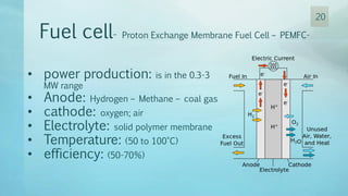
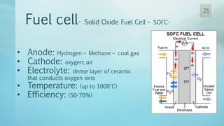
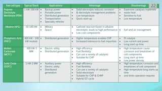
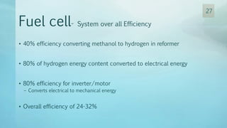
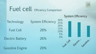
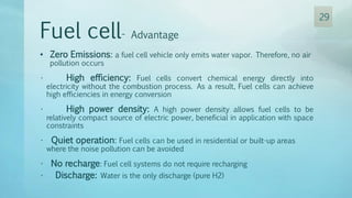
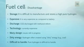
1
HYDROGEN ENERGY
Fuel cells
2
Group Members:
3
Mohamed
AbdEl-hamid
Mahmoud
Ahmed Mohamed
Elkholy
Ahmed Abdel-
hafez
Ahmed Fahmy
Aggour
Agenda
• Introduction
• History
• Theory of Operation
• Hydrogen
– Production
– storage
• Fuel cells electrical characteristics
• Fuel cell types
• Fuel cell- advantage and disadvantage
• Fuel cell application
• Future of fuel cell
• Case study
4
Introduction
• Cars and Trucks using petroleum fuels are
one of the leading causes of air pollution.
• Air pollution is single handedly
responsible for up to 30,000 premature
deaths each year.
• Global warming due to continuous
increase in temperature.
• Getting hard to fulfill the increasing fuel
requirements.
• Acid rain which is harmful for humans and
plants equally.
5
History
• 1839, the first fuel cell created by sir William Grone called “The Gas Battery”
• 1932, Francis Bacon Makes the first functional fuel cell
• 1950, General Electric creates the PEM fuel cell
• 1960, First commercial use by NASA space Programs to generate power
• 1966, General motors developed the First fuel cell road vehicle “Chevrolet
Electrovan”
• 1980, United States navy starts to equip submarines with fuel cell.
• 1990, Stationary fuel cell are used to power building.
• 2005, Fuel cell start becoming available to the public.
6
Theory of Operation
7
Fuel cells - Description
oxygen
electricity
heat
Fuel cell water
hydrogen
• colorless, odorless
and tasteless gas
• chemically active
and rarely exists in
nature in its pure
form
8
Hydrogen - production
• Steam reforming
• Electrolyzing
– Liquid
– Steam
• Thermal
• Thermochemical
• reacting steam with petroleum
hydrocarbons
• These reactions occur at temperatures
of 200°C or higher
• Liquid
• charging the water with an
electrical
• Adding electrolyte as salt to
increase conductivity
• Steam
• Like liquid but more heat is added
rather than electricity
• At 2500°C water decomposes into
hydrogen and oxygen
• To prevent recombine we use 3000°C
• This heat can be providing by solar
energy
• chemicals such as bromine or iodine is
used
9
Hydrogen – Storage – liquid storage
Liquid Storage
• Cooling below boiling point -252.7°C allows
storage as liquid without the need for
pressurization.
• takes up 1/700 of gas volume enabling to
stored and transported much more.
• Slush -liquid and solid- produced by subjecting
the liquid to the vacuum enabling to store
more
• difficult and expensive process
• consumes the equivalent of 25-30% of its
energy content.
• To cool 1 kg of hydrogen 11.1 kWh of electrical
energy is required.
• Liquid Storage
• Gas Storage
• Metal Hydrides
• Gas on Solid Adsorption
• Microspheres
10
Hydrogen – Storage – Gas storage
gas Storage
• less energy than converting to liquid form.
• pressurized to store any appreciable amount.
• pressurized hydrogen could be stored in
caverns, gas-fields and mines.
• Highly expensive tank can be fabricated with
New materials such as carbon fiber.
• Not economically for transportation.
• Liquid Storage
•Gas Storage
• Metal Hydrides
• Gas on Solid Adsorption
• Microspheres
11
Hydrogen – Storage – Metal Hydrides
Metal Hydrides
• chemical compounds of hydrogen and other
material such as magnesium, nickel, copper,
iron and titanium.
• metal alloys absorb hydrogen and release it
when heated
• higher densities than by simple compression..
• Liquid Storage
• Gas Storage
•Metal Hydrides
• Gas on Solid Adsorption
• Microspheres
12
Hydrogen – Storage – Gas on Solid Adsorption
Gas on Solid Adsorption
• Hydrogen can be stored by Adsorption on
activated charcoal (carbon)
• Approach the storage density of liquid
hydrogen.
• Liquid Storage
• Gas Storage
• Metal Hydrides
•Gas on Solid Adsorption
• Microspheres the adhesion of atoms, ions, or molecules from a gas,
liquid, or dissolved solid to a surface.
13
Hydrogen – Storage – Microspheres
Microspheres
• Very small glass spheres hold hydrogen at high
pressures.
• Steps
1. charged with gas at high temperatures where
the gas can pass through the glass wall
2. At low temperature the glass is impervious to
hydrogen and it is locked in.
• Liquid Storage
• Gas Storage
• Metal Hydrides
• Gas on Solid Adsorption
•Microspheres
14
Fuel cell stack - operations
Anode
• Hydrogen entrance
• Positive charge
cathode
• oxygen entrance
• Negative charge
electrolyte
15
Fuel cell stack - type
• Alkaline Fuel Cell –AFC -
– A liquid potassium hydroxide is used in AFC as an electrolyte
• Phosphoric Acid Fuel Cell – PAFC -
– liquid phosphoric acid as an electrolyte
• Molten Carbonate Fuel Cell –MCFC-
– composed of a molten carbonate salt mixture suspended in a porous,
chemically inert ceramic matrix of beta-alumina solid electrolyte (BASE).
• Solid Oxide Fuel Cell –SOFC-
– dense layer of ceramic that conducts oxygen ions
• Proton Exchange Membrane Fuel Cell – PEMFC-
– solid polymer membrane - platinum catalyst – used as an electronic
insulator
16
Fuel cell - Alkaline Fuel Cell –AFC -
• Used in NASA in 60’s
• Anode: pure hydrogen
• cathode: pure oxygen
• Electrolyte: liquid potassium
hydroxide
• Temperature: (80-100°C) gives a
fast-start
• efficiency: (50-60%)
17
Fuel cell - Phosphoric Acid Fuel Cell– PAFC -
• electrolyte is solid
• Anode: Hydrogen – Methane
• cathode: oxygen; air
• Electrolyte: pure liquid phosphoric acid
• Temperature: (160-200°C)
• efficiency: (40%) up to (70%) if
produced steam is used
18
Fuel cell-Molten Carbonate Fuel Cell –MCFC-
• power production: is in the 0.3-3
MW range
• Anode: Hydrogen – Methane – coal gas
• cathode: oxygen; air
• Electrolyte: Melton carbonite
• Temperature: (650°C) high
temperature operation
• efficiency: (45-65%)
19
Fuel cell- Proton Exchange Membrane Fuel Cell – PEMFC-
• power production: is in the 0.3-3
MW range
• Anode: Hydrogen – Methane – coal gas
• cathode: oxygen; air
• Electrolyte: solid polymer membrane
• Temperature: (50 to 100°C)
• efficiency: (50-70%)
20
Fuel cell- Solid Oxide Fuel Cell – SOFC-
• Anode: Hydrogen – Methane – coal gas
• Cathode: oxygen; air
• Electrolyte: dense layer of ceramic
that conducts oxygen ions
• Temperature: (up to 1000°C)
• Efficiency: (50-70%)
21
fuel cell type Typical Stack Applications Advantage Disadvantage
Polymer
Electrolyte
Membrane (PEM)
1 kW-100 kW  Backup power
 Portable power
 Distributed generation
 Transportation
 Specialty vehicles
 Solid electrolyte reduces corrosion
 & electrolyte management problems
 Low temperature
 Quick start-up
 Expensive catalysts impurities
 waste heat
 Sensitive to fuel
 Low temperature
Alkaline (AFC) 10-100 kW  Military
 Space
 Cathode reaction faster in alkaline
electrolyte, leads to high performance
 Low cost components
 fuel and air management
Phosphoric Acid
(PAFC)
400 kW - 100
kW module
 Distributed generation  Higher temperature enables CHP
 Increased tolerance to fuel impurities
 Pt catalyst
 Low current and power
 Long start up time
Molten
Carbonate
(MCFC)
300 kW-3
MW
 Electric utility
 Distributed generation
 High efficiency
 Fuel flexibility
 Can use a variety of catalysts
 Suitable for CHP
 High temperature cause
corrosion and breakdown of
cell components
 Long start up time
 Low power density
Solid Oxide
(SOFC)
1 kW-2 MW  Auxiliary power
 Electric utility
 Distributed
generation
 High efficiency
 Fuel flexibility
 Can use a variety of catalysts
 Solid electrolyte
 Suitable for CHP & CHHP
 Hybrid/GT cycle
 High temperature corrosion and
breakdown of cell component
 High temperature long starts up
time
 and limits operation requires
22
23
Fuel cells Block diagram
24
Fuel cells characteristics
25
Fuel cells characteristics
𝑅 𝛺, 𝑅 𝐻2
, 𝑅 𝑂2
..the internal
resistance, anode reaction and
cathode reaction respectively
• region 1 the sharp drop in the
voltage is caused by the chemical
reaction
• region 2 the voltage drop is caused
by the losses in the electrode
structure and the electrolyte, which is
almost constant
• region 3 the voltage drop is defined
by the rate of reaction diffusion
• the current reaches a maximum value
called the limiting current
26
• 40% efficiency converting methanol to hydrogen in reformer
• 80% of hydrogen energy content converted to electrical energy
• 80% efficiency for inverter/motor
– Converts electrical to mechanical energy
• Overall efficiency of 24-32%
Fuel cell- System over all Efficiency
27
28
Technology System Efficiency
Fuel Cell 28%
Electric Battery 26%
Gasoline Engine 20%
Fuel cell- Efficiency Comparison
0%
5%
10%
15%
20%
25%
30%
System Efficiency
Fuel cell- Advantage
• Zero Emissions: a fuel cell vehicle only emits water vapor. Therefore, no air
pollution occurs
• High efficiency: Fuel cells convert chemical energy directly into
electricity without the combustion process. As a result, Fuel cells can achieve
high efficiencies in energy conversion
• High power density: A high power density allows fuel cells to be
relatively compact source of electric power, beneficial in application with space
constraints
• Quiet operation: Fuel cells can be used in residential or built-up areas
where the noise pollution can be avoided
• No recharge: Fuel cell systems do not require recharging
• Discharge: Water is the only discharge (pure H2)
29
• Storage: It is difficult to manufacture and stores a high pure hydrogen
• Expensive: It is very expensive as compared to battery
• Discharge: CO2 discharged with methanol reform
• Technology: currently expensive
• Many design: issues still in progress
• Dirty energy: Hydrogen often created using “dirty” energy (e.g., coal)
• Difficult to handle: Pure hydrogen is difficult to handle
Fuel cell- Disadvantage
30
Fuel cell- Applications
Transport Portable
Stationary
31
• Units that produce propulsive power or range extension
to a vehicle
• Technologies used are PEMFC and DMFC.
• Ranges from 1KW to 100KW.
• The Fuel Cell Electric Vehicles (FCEV) such as trucks and
buses sector is showing year-on-year growth.
• Successful deployments have taken place in Europe,
Japan, Canada and the USA
Fuel cell- Applications - Transport
32
• Forklift trucks and other goods handling vehicles
such as airport baggage trucks, etc.
• Light duty vehicles (LDVs), such as cars and vans
• Buses and trucks
• Submarines, Ferries and smaller boat
Fuel cell- Applications - Transport
33
Fuel cell- Applications - Transport
34
Fuel cell- Applications - Transport
Ford Focus FCV
Honda Fuel Cell
Vehicles-2003Ford H2RV
35
• A 30 ft. Hydrogen Fuel
cell powered transit bus
made by Ballard Power
Systems in Canada.
• It has a 275 horsepower
engine, and a range of
250 miles before requiring
refueling.
• The only emission from
this bus is warm, moist
air.
Fuel cell- Applications - Transport
36
• Advantage of virtually silent
operation, Fuel cells are
especially suited for silent
operations because of their low
heat and noise signatures
• Air-independent systems
increase underwater endurance
• Used German Navy, Greek Navy,
South, Korean Navy and Italian
Navy, US Navy has no
operational fuel cell powered
subs but is actively engaged in
research
Fuel cell- Applications - Transport
37
• Portable fuel cells are those which are built
into, or charge up, products that are
designed to be moved (They can be used in
Backup power)
• These include military applications, auxiliary
power units, personal electronics, portable
products
• Ranges from 5W up to 20KW.
• Technologies used are PEMFC and DMFC.
• Rapid recharging, Convenience, reliability,
low operating, significant weight reduction
potential (for soldier-borne military power)
and longer run-times compared with
batteries
Fuel cell- Applications - Portable
38
• Unmanned Aerial Vehicles
• Decreased costs over battery systems.
• Department of Defense and United
States Air Force are funding UAV
projects
• In 2009 over $3.5 million dollars have
been awarded in contracts to
companies
• working on miniaturizing fuel cells for
UAVs
Fuel cell- Applications - Portable
39
• Soldier Portable Power
• -Soldiers are carrying more and more
energy (30-50) Watts - (more than 50
pounds) using more than 20 different type
of batteries.
• - Fuel cells can be used to re-charge
batteries in the field, as well as act as
generators.
• -As an example M-25 Modular Fuel Cell
Power System used in Land Warrior 72
Hour Mission
Fuel cell- Applications - Portable
40
• Stationary fuel cells are units which provide
electricity but are not designed to be
moved
• Power ranges from 0.5KW to 1MW
• Technologies used are PEMFC, PAFC, MCFC
and SOFC
• These include combined heat and power
(CHP), uninterruptible power systems (UPS)
and primary power units
• Residential CHP units have been deployed
extensively in Japan with more than 10,000
cumulative units by the end of 2010 and
South Korea has also deployed CHP units
for residential use
Fuel cell- Applications - Stationary
41
Future
2015 – 2025- Substantial markets for
hydrogen-powered vehicles likely to
start developing
2020: 5 to 10 million hydrogen-powered cars
2030: 50 million hydrogen powered cars
2040: 150 million hydrogen-powered cars
42
Case study
• Paper named Optimal Design of a PV/Fuel Cell Hybrid Power
System for the City of Brest in France, performed by Omar Hazem
Mohammed, Yassine Amirat, Mohamed Benbouzid,University of
Brest
• Cited by IEEE Publications, 2015,IEEE15th International Conference
• focused on economical performances and is mainly based on the
loss of the power supply probability concept.
• The hybrid power system optimal design is based on a simulation
model developed using HOMER, the site of software
http://www.homerenergy.com/
• a practical load demand profile of Brest city is used with real data
43
Case study SYSTEM DESCRIPTION
where the hybrid power
system consists
1.PV generators
2.fuel cells
3.Electrolyzer
4.hydrogen tank,
44
Case study SYSTEM DESCRIPTION
The city of Brest load demand
• should be noted that the 2MW
annual peak load occurs in
January
• The largest demand occurs
during the peak season
(between December and
January)
• The lowest demand happens
during the low season (between
July and September)
45
Case study SYSTEM DESCRIPTION
• solar radiation data
were obtained from
the NASA
Atmospheric Data
Center
• The annual average
solar radiation for
this area is about
3.39 kWh/m²/day
Monthly average daily solar radiation
46
Case study HOMER inputs and system configuration
INPUT DATA ON OPTION COSTS
INPUT DATA ON OPTION SIZING AND OTHER PARAMETERS
47
• The model constraints include:
– Maximum annual capacity shortage is 0%
– Operating reserve is considered to be 10% of the hourly load
• The operational control strategy (power management)
– In normal operation, the PV generator supplies the load demand the power
excess will be used to feed the electrolyzer for hydrogen production and
storage in the tank
– If the PV generator power is less than the load demand, FCs will generate
the remaining power to supply the load demand. FCs should fully supply the
load demand in case of no radiation
Case study constraint and strategy
48
• simulation is carrying-out
several with a 3.39
kWh/m²/day solar
radiation
• and considering different
PV, FC, electrolyzer,
hydrogen tank, and
converter capacities
Case study optimization results
49
50

Fuel cell

  • 1.
  • 2.
  • 3.
  • 4.
    Agenda • Introduction • History •Theory of Operation • Hydrogen – Production – storage • Fuel cells electrical characteristics • Fuel cell types • Fuel cell- advantage and disadvantage • Fuel cell application • Future of fuel cell • Case study 4
  • 5.
    Introduction • Cars andTrucks using petroleum fuels are one of the leading causes of air pollution. • Air pollution is single handedly responsible for up to 30,000 premature deaths each year. • Global warming due to continuous increase in temperature. • Getting hard to fulfill the increasing fuel requirements. • Acid rain which is harmful for humans and plants equally. 5
  • 6.
    History • 1839, thefirst fuel cell created by sir William Grone called “The Gas Battery” • 1932, Francis Bacon Makes the first functional fuel cell • 1950, General Electric creates the PEM fuel cell • 1960, First commercial use by NASA space Programs to generate power • 1966, General motors developed the First fuel cell road vehicle “Chevrolet Electrovan” • 1980, United States navy starts to equip submarines with fuel cell. • 1990, Stationary fuel cell are used to power building. • 2005, Fuel cell start becoming available to the public. 6
  • 7.
  • 8.
    Fuel cells -Description oxygen electricity heat Fuel cell water hydrogen • colorless, odorless and tasteless gas • chemically active and rarely exists in nature in its pure form 8
  • 9.
    Hydrogen - production •Steam reforming • Electrolyzing – Liquid – Steam • Thermal • Thermochemical • reacting steam with petroleum hydrocarbons • These reactions occur at temperatures of 200°C or higher • Liquid • charging the water with an electrical • Adding electrolyte as salt to increase conductivity • Steam • Like liquid but more heat is added rather than electricity • At 2500°C water decomposes into hydrogen and oxygen • To prevent recombine we use 3000°C • This heat can be providing by solar energy • chemicals such as bromine or iodine is used 9
  • 10.
    Hydrogen – Storage– liquid storage Liquid Storage • Cooling below boiling point -252.7°C allows storage as liquid without the need for pressurization. • takes up 1/700 of gas volume enabling to stored and transported much more. • Slush -liquid and solid- produced by subjecting the liquid to the vacuum enabling to store more • difficult and expensive process • consumes the equivalent of 25-30% of its energy content. • To cool 1 kg of hydrogen 11.1 kWh of electrical energy is required. • Liquid Storage • Gas Storage • Metal Hydrides • Gas on Solid Adsorption • Microspheres 10
  • 11.
    Hydrogen – Storage– Gas storage gas Storage • less energy than converting to liquid form. • pressurized to store any appreciable amount. • pressurized hydrogen could be stored in caverns, gas-fields and mines. • Highly expensive tank can be fabricated with New materials such as carbon fiber. • Not economically for transportation. • Liquid Storage •Gas Storage • Metal Hydrides • Gas on Solid Adsorption • Microspheres 11
  • 12.
    Hydrogen – Storage– Metal Hydrides Metal Hydrides • chemical compounds of hydrogen and other material such as magnesium, nickel, copper, iron and titanium. • metal alloys absorb hydrogen and release it when heated • higher densities than by simple compression.. • Liquid Storage • Gas Storage •Metal Hydrides • Gas on Solid Adsorption • Microspheres 12
  • 13.
    Hydrogen – Storage– Gas on Solid Adsorption Gas on Solid Adsorption • Hydrogen can be stored by Adsorption on activated charcoal (carbon) • Approach the storage density of liquid hydrogen. • Liquid Storage • Gas Storage • Metal Hydrides •Gas on Solid Adsorption • Microspheres the adhesion of atoms, ions, or molecules from a gas, liquid, or dissolved solid to a surface. 13
  • 14.
    Hydrogen – Storage– Microspheres Microspheres • Very small glass spheres hold hydrogen at high pressures. • Steps 1. charged with gas at high temperatures where the gas can pass through the glass wall 2. At low temperature the glass is impervious to hydrogen and it is locked in. • Liquid Storage • Gas Storage • Metal Hydrides • Gas on Solid Adsorption •Microspheres 14
  • 15.
    Fuel cell stack- operations Anode • Hydrogen entrance • Positive charge cathode • oxygen entrance • Negative charge electrolyte 15
  • 16.
    Fuel cell stack- type • Alkaline Fuel Cell –AFC - – A liquid potassium hydroxide is used in AFC as an electrolyte • Phosphoric Acid Fuel Cell – PAFC - – liquid phosphoric acid as an electrolyte • Molten Carbonate Fuel Cell –MCFC- – composed of a molten carbonate salt mixture suspended in a porous, chemically inert ceramic matrix of beta-alumina solid electrolyte (BASE). • Solid Oxide Fuel Cell –SOFC- – dense layer of ceramic that conducts oxygen ions • Proton Exchange Membrane Fuel Cell – PEMFC- – solid polymer membrane - platinum catalyst – used as an electronic insulator 16
  • 17.
    Fuel cell -Alkaline Fuel Cell –AFC - • Used in NASA in 60’s • Anode: pure hydrogen • cathode: pure oxygen • Electrolyte: liquid potassium hydroxide • Temperature: (80-100°C) gives a fast-start • efficiency: (50-60%) 17
  • 18.
    Fuel cell -Phosphoric Acid Fuel Cell– PAFC - • electrolyte is solid • Anode: Hydrogen – Methane • cathode: oxygen; air • Electrolyte: pure liquid phosphoric acid • Temperature: (160-200°C) • efficiency: (40%) up to (70%) if produced steam is used 18
  • 19.
    Fuel cell-Molten CarbonateFuel Cell –MCFC- • power production: is in the 0.3-3 MW range • Anode: Hydrogen – Methane – coal gas • cathode: oxygen; air • Electrolyte: Melton carbonite • Temperature: (650°C) high temperature operation • efficiency: (45-65%) 19
  • 20.
    Fuel cell- ProtonExchange Membrane Fuel Cell – PEMFC- • power production: is in the 0.3-3 MW range • Anode: Hydrogen – Methane – coal gas • cathode: oxygen; air • Electrolyte: solid polymer membrane • Temperature: (50 to 100°C) • efficiency: (50-70%) 20
  • 21.
    Fuel cell- SolidOxide Fuel Cell – SOFC- • Anode: Hydrogen – Methane – coal gas • Cathode: oxygen; air • Electrolyte: dense layer of ceramic that conducts oxygen ions • Temperature: (up to 1000°C) • Efficiency: (50-70%) 21
  • 22.
    fuel cell typeTypical Stack Applications Advantage Disadvantage Polymer Electrolyte Membrane (PEM) 1 kW-100 kW  Backup power  Portable power  Distributed generation  Transportation  Specialty vehicles  Solid electrolyte reduces corrosion  & electrolyte management problems  Low temperature  Quick start-up  Expensive catalysts impurities  waste heat  Sensitive to fuel  Low temperature Alkaline (AFC) 10-100 kW  Military  Space  Cathode reaction faster in alkaline electrolyte, leads to high performance  Low cost components  fuel and air management Phosphoric Acid (PAFC) 400 kW - 100 kW module  Distributed generation  Higher temperature enables CHP  Increased tolerance to fuel impurities  Pt catalyst  Low current and power  Long start up time Molten Carbonate (MCFC) 300 kW-3 MW  Electric utility  Distributed generation  High efficiency  Fuel flexibility  Can use a variety of catalysts  Suitable for CHP  High temperature cause corrosion and breakdown of cell components  Long start up time  Low power density Solid Oxide (SOFC) 1 kW-2 MW  Auxiliary power  Electric utility  Distributed generation  High efficiency  Fuel flexibility  Can use a variety of catalysts  Solid electrolyte  Suitable for CHP & CHHP  Hybrid/GT cycle  High temperature corrosion and breakdown of cell component  High temperature long starts up time  and limits operation requires 22
  • 23.
  • 24.
  • 25.
  • 26.
    Fuel cells characteristics 𝑅𝛺, 𝑅 𝐻2 , 𝑅 𝑂2 ..the internal resistance, anode reaction and cathode reaction respectively • region 1 the sharp drop in the voltage is caused by the chemical reaction • region 2 the voltage drop is caused by the losses in the electrode structure and the electrolyte, which is almost constant • region 3 the voltage drop is defined by the rate of reaction diffusion • the current reaches a maximum value called the limiting current 26
  • 27.
    • 40% efficiencyconverting methanol to hydrogen in reformer • 80% of hydrogen energy content converted to electrical energy • 80% efficiency for inverter/motor – Converts electrical to mechanical energy • Overall efficiency of 24-32% Fuel cell- System over all Efficiency 27
  • 28.
    28 Technology System Efficiency FuelCell 28% Electric Battery 26% Gasoline Engine 20% Fuel cell- Efficiency Comparison 0% 5% 10% 15% 20% 25% 30% System Efficiency
  • 29.
    Fuel cell- Advantage •Zero Emissions: a fuel cell vehicle only emits water vapor. Therefore, no air pollution occurs • High efficiency: Fuel cells convert chemical energy directly into electricity without the combustion process. As a result, Fuel cells can achieve high efficiencies in energy conversion • High power density: A high power density allows fuel cells to be relatively compact source of electric power, beneficial in application with space constraints • Quiet operation: Fuel cells can be used in residential or built-up areas where the noise pollution can be avoided • No recharge: Fuel cell systems do not require recharging • Discharge: Water is the only discharge (pure H2) 29
  • 30.
    • Storage: Itis difficult to manufacture and stores a high pure hydrogen • Expensive: It is very expensive as compared to battery • Discharge: CO2 discharged with methanol reform • Technology: currently expensive • Many design: issues still in progress • Dirty energy: Hydrogen often created using “dirty” energy (e.g., coal) • Difficult to handle: Pure hydrogen is difficult to handle Fuel cell- Disadvantage 30
  • 31.
    Fuel cell- Applications TransportPortable Stationary 31
  • 32.
    • Units thatproduce propulsive power or range extension to a vehicle • Technologies used are PEMFC and DMFC. • Ranges from 1KW to 100KW. • The Fuel Cell Electric Vehicles (FCEV) such as trucks and buses sector is showing year-on-year growth. • Successful deployments have taken place in Europe, Japan, Canada and the USA Fuel cell- Applications - Transport 32
  • 33.
    • Forklift trucksand other goods handling vehicles such as airport baggage trucks, etc. • Light duty vehicles (LDVs), such as cars and vans • Buses and trucks • Submarines, Ferries and smaller boat Fuel cell- Applications - Transport 33
  • 34.
  • 35.
    Fuel cell- Applications- Transport Ford Focus FCV Honda Fuel Cell Vehicles-2003Ford H2RV 35
  • 36.
    • A 30ft. Hydrogen Fuel cell powered transit bus made by Ballard Power Systems in Canada. • It has a 275 horsepower engine, and a range of 250 miles before requiring refueling. • The only emission from this bus is warm, moist air. Fuel cell- Applications - Transport 36
  • 37.
    • Advantage ofvirtually silent operation, Fuel cells are especially suited for silent operations because of their low heat and noise signatures • Air-independent systems increase underwater endurance • Used German Navy, Greek Navy, South, Korean Navy and Italian Navy, US Navy has no operational fuel cell powered subs but is actively engaged in research Fuel cell- Applications - Transport 37
  • 38.
    • Portable fuelcells are those which are built into, or charge up, products that are designed to be moved (They can be used in Backup power) • These include military applications, auxiliary power units, personal electronics, portable products • Ranges from 5W up to 20KW. • Technologies used are PEMFC and DMFC. • Rapid recharging, Convenience, reliability, low operating, significant weight reduction potential (for soldier-borne military power) and longer run-times compared with batteries Fuel cell- Applications - Portable 38
  • 39.
    • Unmanned AerialVehicles • Decreased costs over battery systems. • Department of Defense and United States Air Force are funding UAV projects • In 2009 over $3.5 million dollars have been awarded in contracts to companies • working on miniaturizing fuel cells for UAVs Fuel cell- Applications - Portable 39
  • 40.
    • Soldier PortablePower • -Soldiers are carrying more and more energy (30-50) Watts - (more than 50 pounds) using more than 20 different type of batteries. • - Fuel cells can be used to re-charge batteries in the field, as well as act as generators. • -As an example M-25 Modular Fuel Cell Power System used in Land Warrior 72 Hour Mission Fuel cell- Applications - Portable 40
  • 41.
    • Stationary fuelcells are units which provide electricity but are not designed to be moved • Power ranges from 0.5KW to 1MW • Technologies used are PEMFC, PAFC, MCFC and SOFC • These include combined heat and power (CHP), uninterruptible power systems (UPS) and primary power units • Residential CHP units have been deployed extensively in Japan with more than 10,000 cumulative units by the end of 2010 and South Korea has also deployed CHP units for residential use Fuel cell- Applications - Stationary 41
  • 42.
    Future 2015 – 2025-Substantial markets for hydrogen-powered vehicles likely to start developing 2020: 5 to 10 million hydrogen-powered cars 2030: 50 million hydrogen powered cars 2040: 150 million hydrogen-powered cars 42
  • 43.
    Case study • Papernamed Optimal Design of a PV/Fuel Cell Hybrid Power System for the City of Brest in France, performed by Omar Hazem Mohammed, Yassine Amirat, Mohamed Benbouzid,University of Brest • Cited by IEEE Publications, 2015,IEEE15th International Conference • focused on economical performances and is mainly based on the loss of the power supply probability concept. • The hybrid power system optimal design is based on a simulation model developed using HOMER, the site of software http://www.homerenergy.com/ • a practical load demand profile of Brest city is used with real data 43
  • 44.
    Case study SYSTEMDESCRIPTION where the hybrid power system consists 1.PV generators 2.fuel cells 3.Electrolyzer 4.hydrogen tank, 44
  • 45.
    Case study SYSTEMDESCRIPTION The city of Brest load demand • should be noted that the 2MW annual peak load occurs in January • The largest demand occurs during the peak season (between December and January) • The lowest demand happens during the low season (between July and September) 45
  • 46.
    Case study SYSTEMDESCRIPTION • solar radiation data were obtained from the NASA Atmospheric Data Center • The annual average solar radiation for this area is about 3.39 kWh/m²/day Monthly average daily solar radiation 46
  • 47.
    Case study HOMERinputs and system configuration INPUT DATA ON OPTION COSTS INPUT DATA ON OPTION SIZING AND OTHER PARAMETERS 47
  • 48.
    • The modelconstraints include: – Maximum annual capacity shortage is 0% – Operating reserve is considered to be 10% of the hourly load • The operational control strategy (power management) – In normal operation, the PV generator supplies the load demand the power excess will be used to feed the electrolyzer for hydrogen production and storage in the tank – If the PV generator power is less than the load demand, FCs will generate the remaining power to supply the load demand. FCs should fully supply the load demand in case of no radiation Case study constraint and strategy 48
  • 49.
    • simulation iscarrying-out several with a 3.39 kWh/m²/day solar radiation • and considering different PV, FC, electrolyzer, hydrogen tank, and converter capacities Case study optimization results 49
  • 50.