Transmitters:
Classification of Transmitters:The radio transmitters may be classified
according to the type of modulation used:
1. AM Transmitter: Amplitude modulation is used.
2. FM Transmitter: Frequency modulation technique is used.
Classification according to the carrier frequency used:
1. Long Wave Transmitter (30-300kHz): Used for aeronautical and marine
navigation.
2. Medium Wave Transmitter (300-3000kHz): Used for AM broadcasting.
3. Short Wave Transmitters (3-30MHz): Used for long-distance AM
communication by virtue of ionospheric reflection.
4. FM Transmitters: Very high-frequency transmitters (30-300MHz) used
for mobile radio, television broadcasting, aeronautical and marine
communication.
5. UHF Transmitters (300-3000MHz): Used for television broadcasting,
cellular telephony, and military services.
6. Frequencies above 1000MHz are called microwave and are used for radar
and satellite communications.
Classification according to the type of service involved:
1. Radio Telegraph Transmitter: May use both AM and FM.
2. Television Transmitter: Requires two transmitters - one for the
transmission of pictures and another for sound. Picture transmission is
done using AM and sound transmission is done using FM.
3. Radar Transmitters and navigational transmitter.
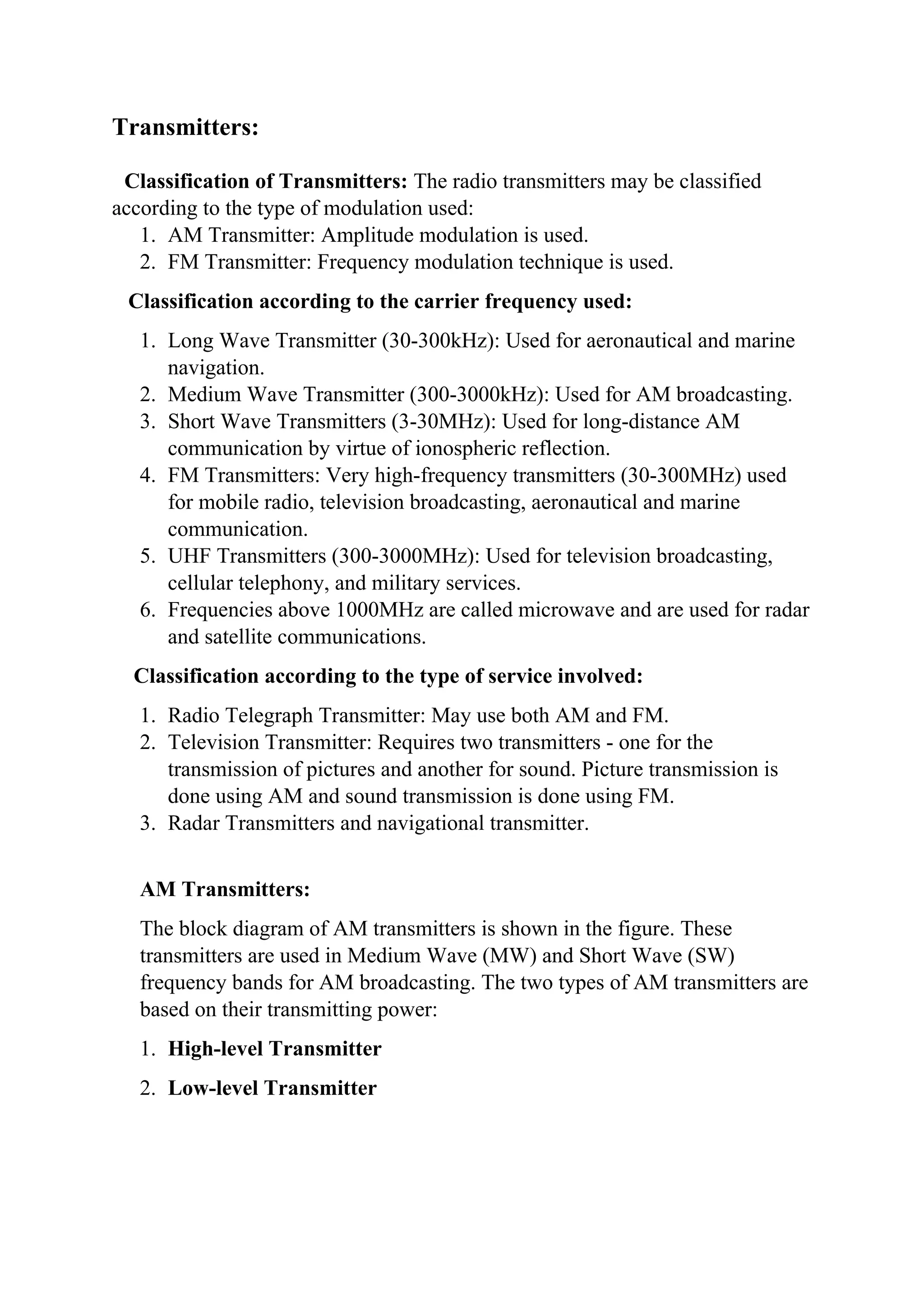
AM Transmitters:
The block diagram of AM transmitters is shown in the figure. These
transmitters are used in Medium Wave (MW) and Short Wave (SW)
frequency bands for AM broadcasting. The two types of AM transmitters are
based on their transmitting power:
1. High-level Transmitter
2. Low-level Transmitter
2.
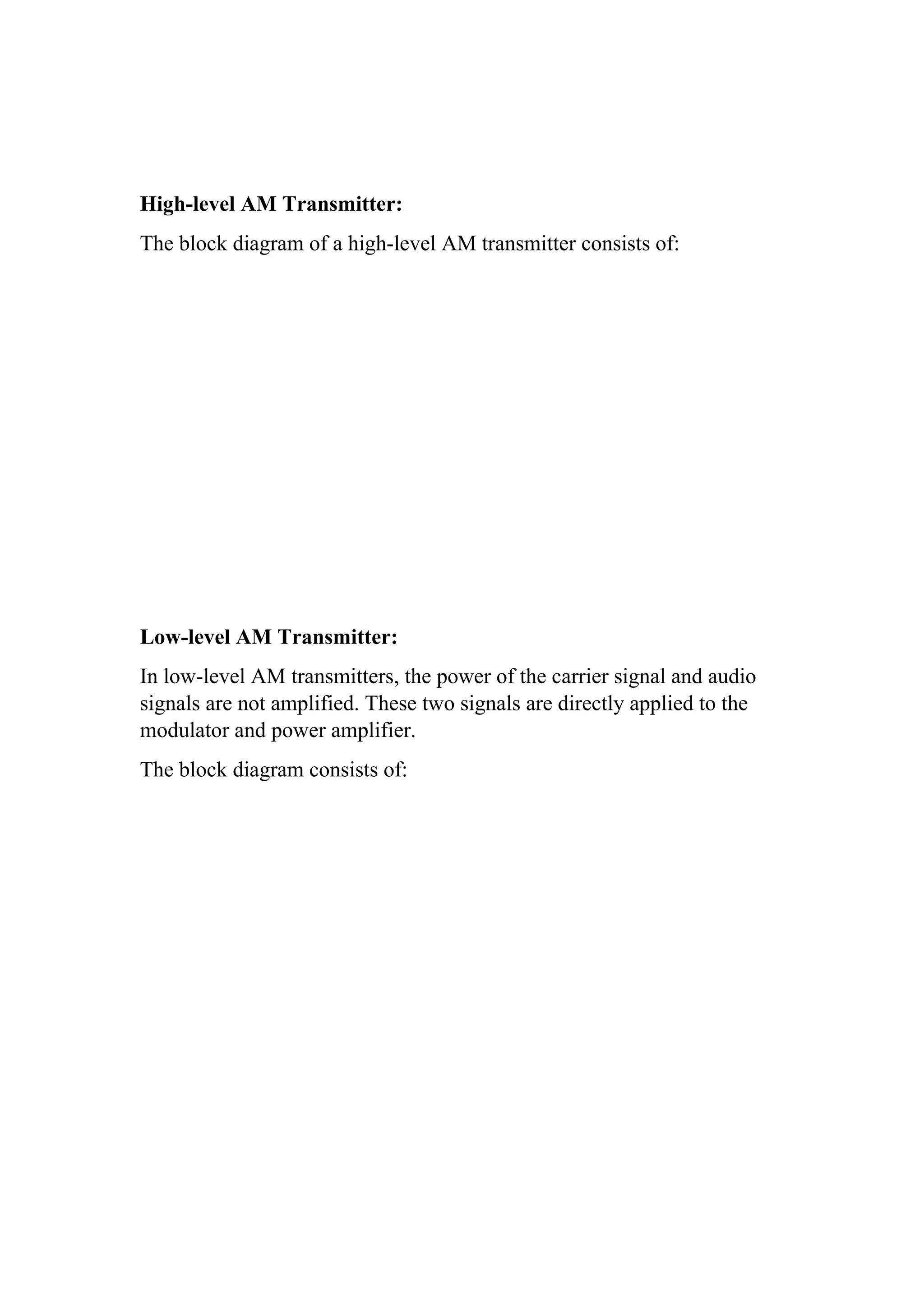
High-level AM Transmitter:
Theblock diagram of a high-level AM transmitter consists of:
Low-level AM Transmitter:
In low-level AM transmitters, the power of the carrier signal and audio
signals are not amplified. These two signals are directly applied to the
modulator and power amplifier.
The block diagram consists of:
3.
Various Sections ofAM Transmitters:
1. Carrier Oscillator:
The carrier oscillator generates the carrier signal, which lies in the RF
(Radio Frequency) range. The frequency of the carrier is usually very
high.
2. Power Amplifier:
The power amplifier is the stage where the power of the carrier signal
is amplified. This is mainly required for high-level transmitters. A class C
power amplifier is generally used to provide high-power current pulses at
the carrier signal.
3. Modulated Class C Power Amplifier:
This is the final stage of the transmitter. The modulating signal (audio
signal) and the carrier signal, after power amplification, are applied to the
modulating stage. The class C power amplifier amplifies the power of the
AM signal to the required transmitting power. This final signal is then
sent to the antenna for transmission.
Use of Feedback in AM Transmitters
Feedback is used in AM radio telephony, particularly in medium power
transmitters. In such cases, the advantages of low-level modulation are
combined with the efficiency derived from classes.
RF Power Amplifier
The distortion in the envelope due to the non-linear class C amplifier can
be minimized by incorporating a feedback arrangement. A simple diode
detector at the transmitter output derives the audio signal envelope from
the RF output. This audio signal is given as a negative feedback signal to
the audio modulator stage. The net effect is that while the RF amplifiers
continue to exhibit the efficiency of class C operation, they still act as a
linear amplifier as far as the actual modulation is concerned
4.
FM Transmitters:
FM signalscan be generated either by the direct method or the indirect
method. In the direct method, FM may be generated using a varactor
diode. In the indirect generation method, a narrowband FM (NBFM)
signal is first obtained using integrators and a phase modulator. This
NBFM signal is then converted to wideband FM (WBFM) using a chain
of frequency multipliers. The generated FM signal is then routed through
power amplifiers and transmitted through the antenna. The block diagram
of the FM transmitter represents the indirect method of generation.
5.
A crystal oscillatoris used to generate a high-stability carrier signal. This
carrier signal is isolated from the rest of the system by a buffer amplifier.
The buffer amplifier acts as a signal conditioner to maintain signal strength.
This carrier signal acts as one of the inputs to a phase modulator. The
baseband signal (modulating signal) is generated and amplified by an Audio
Amplifier. The Pre-emphasis circuit is used to artificially boost the high-
frequency modulating signal to reduce noise interference. The output of the
pre-emphasis circuit is low-pass filtered and then fed as another input to the
phase modulator. The output of the phase modulator is Narrow Band FM
(NBFM). To convert this NBFM into Wide Band FM (WBFM), a chain of
frequency multipliers is used. After obtaining the desired WBFM signal, it is
passed through power amplifiers to boost the transmitting power. The final
amplified signal is transmitted through the antenna is achieved by using
power amplifier.
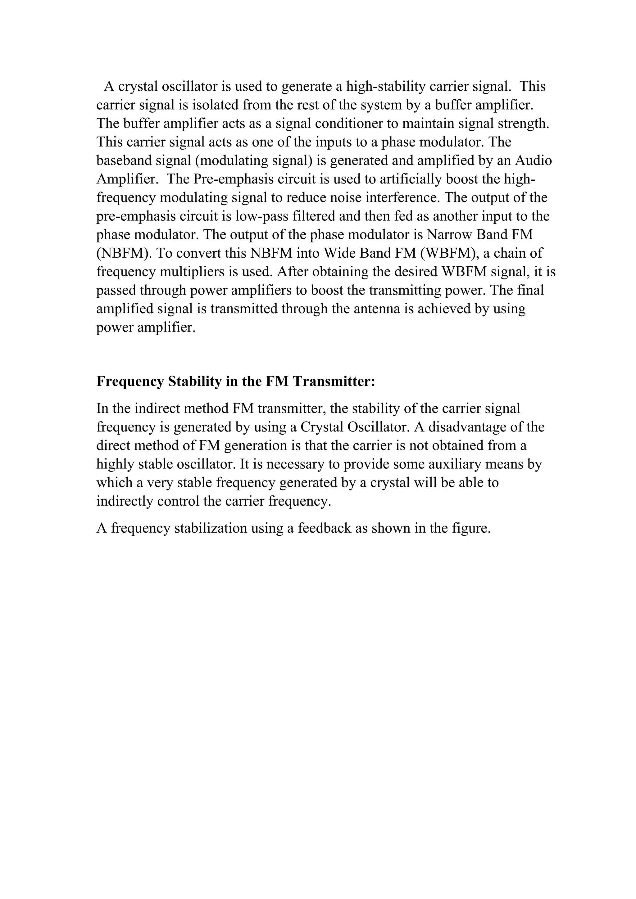
Frequency Stability in the FM Transmitter:
In the indirect method FM transmitter, the stability of the carrier signal
frequency is generated by using a Crystal Oscillator. A disadvantage of the
direct method of FM generation is that the carrier is not obtained from a
highly stable oscillator. It is necessary to provide some auxiliary means by
which a very stable frequency generated by a crystal will be able to
indirectly control the carrier frequency.
A frequency stabilization using a feedback as shown in the figure.
6.
The output ofthe Direct-FM circuit and the crystal oscillator when fed to the
mixer, yield the difference frequency term. The mixer's output is fed to the
frequency discriminator and then low pass filtered.The discriminator
provides here an error voltage that is proportional to the instantaneous
frequency at the input.
When the FM transmitter has a frequency exactly equal to its assigned
carrier frequency. From the low pass filter, output is zero.
Problem 1: In a broadcast Super Heterodyne receiver having RF amplifiers
is tuned to 555 kHz. The local oscillator is adjusted to 1010 kHz. Then
calculate the IF (Intermediate Frequency) and Image Frequency.
Problem 2: In a broadcast Super Heterodyne receiver having no RF
amplifiers is tuned to 555 kHz. The local oscillator frequency is adjusted to
1010 kHz and the quality factor is 50. Calculate the Intermediate Frequency,
Image Frequency, and Image Rejection Ratio.
Solution 1:
Given Incoming Signal Frequency, fs = 555 kHz
The given Local Oscillator Frequency, fo = 1010 kHz
The Intermediate Frequency
fIF = fo−fs = 1010−555kHz =455kHz
The Image Frequency:
fsi=fs+2fi
2fi=910kHz
Solution 2:
Single Stage RF Amplifier
incoming Signal Frequency
fs=555kHz
Local Oscillator Frequency
fo = 1010kHz
Intermediate Frequency
7.
fIF = fo−fs= 455kHz
The given Quality Factor Q = 50
Image Frequency
Fsi = 2×fIF=910kHz