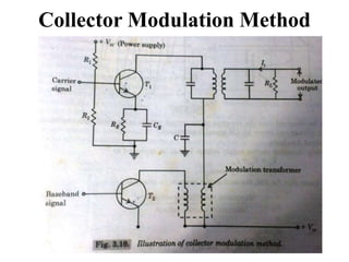
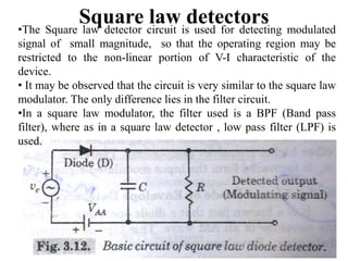
1. This document discusses non-linear signal processing and provides an overview of amplitude modulation (AM), frequency modulation (FM), and their generation and demodulation.
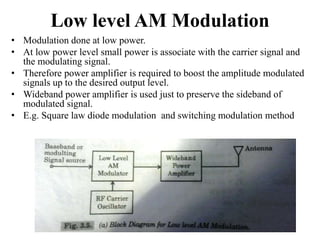
2. It defines key concepts such as modulation, carrier signal, bandwidth, and modulation index. For AM, it describes how the amplitude of the carrier wave is varied by the modulating signal.
3. Methods for generating and demodulating AM signals include square law diode modulation, collector modulation, and envelope detectors. FM varies the instantaneous frequency of the carrier proportionally to the modulating signal.


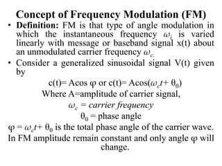
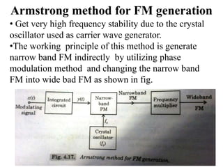
![• Let as x(t) is modulating signal
• The standard equation of AM may expressed
as
s(t)=x(t)cos ωct + Acos ωct
s(t)= [x(t)+A]cos ωct … (2)
• FT (Fourier transform) of cos ωct
is π[δ(ω+ωc )+ δ(ω-ωc )],
So for Acos ωct πA[δ(ω+ωc )+ δ(ω-ωc )]
For x(t) X(ω)
ejωct X(ω-ωc ) and
Similarly e-jωct X(ω+ωc )](https://image.slidesharecdn.com/amandfm-190418094601/85/Non-Linear-Signal-Processing-11-320.jpg)
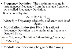
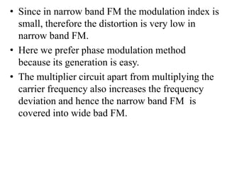
![• So, x(t)cos ωct =x(t) [½ (ejωct + e-jωct )]
= ½ x(t) ejωct + ½ x(t) e-jωct
FT of above equation is
x(t)cos ωct ½ [X(ω+ωc )+ X(ω-ωc )]
So, FT of AM equation is
S(t) S(ω)= ½ [X(ω+ωc )+ X(ω-ωc )]+
πA[δ(ω+ωc )+ δ(ω-ωc )]
BW of AM signal:
BW= [(ω c +ωm )+ (ω c -ωm )]=2 ωm
ωm = modulating signal frequency](https://image.slidesharecdn.com/amandfm-190418094601/85/Non-Linear-Signal-Processing-12-320.jpg)

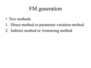
![• Put equation (2) in (1),
i=a[A(1+macos ωmt ) cos ωct]+b[A(1+macos ωmt )
cos ωct]2 … (3)
• Above expression is expanded, the we may observed
the presents of terms of frequencies like
2ωc, 2(ωc± ωm ), ωm, 2ωm besides the input frequency
term.
• Hence the diode current i containing all these
frequencies is pass the frequencies below or up to
modulating frequency ωm and reject the other higher
frequency component.
• Therefore the modulating signal with ωm frequency is
recovered from the input modulated signal.](https://image.slidesharecdn.com/amandfm-190418094601/85/Non-Linear-Signal-Processing-28-320.jpg)