Download as PDF, PPTX

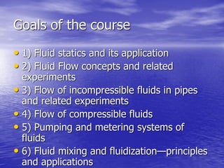
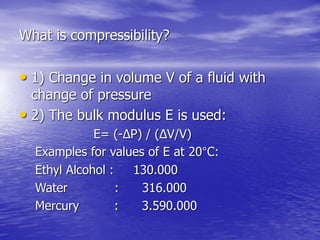

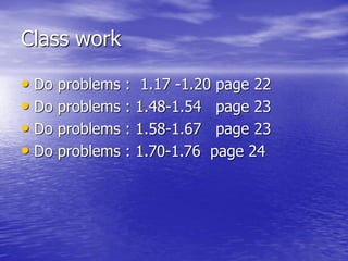

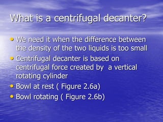
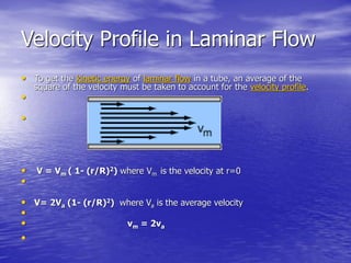
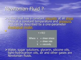
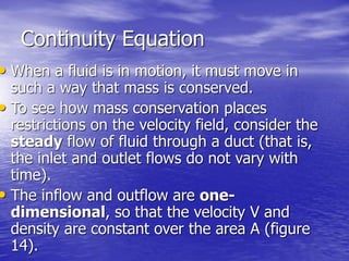
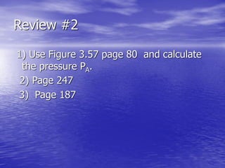
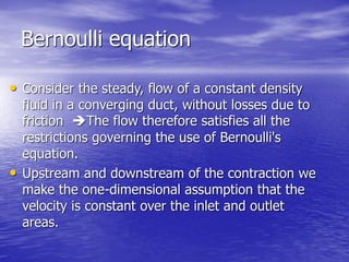
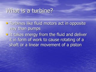
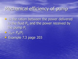
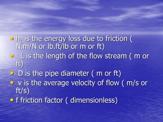
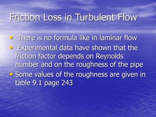
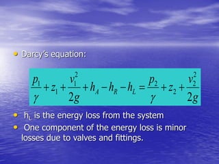
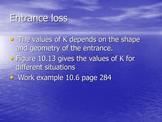
![Calculation of a gravity decanter
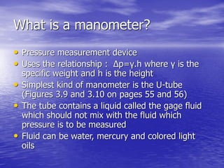
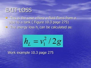
At point 1: P1 =0
At point 4: P4 =P1+ ρA. ZA2= ρA. ZA2
At point 5: P5=P4= ρA. ZA2
At point 2: P2= P5 - ρA. ZA1= ρA. (ZA2- ZA1)
At point 3: P3= 0= P2 - ρB. ZB
P3= ρA. (ZA2- ZA1) - ρB. ZB=0
ZT=ZA1 + ZB =} ρA. (ZA2- ZA1) - ρB.( ZT-ZA1)=0
And finally : ZA1= [ZA2 – ZT (ρB/ ρA)]/ [1- (ρB/ ρA)]](https://image.slidesharecdn.com/fluidmechanicsforchrmical-150729010343-lva1-app6892/85/Fluid-mechanics-for-chermical-engineering-students-20-320.jpg)
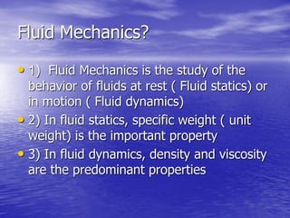
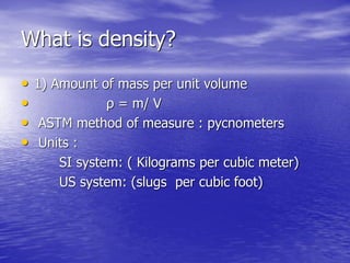
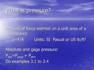
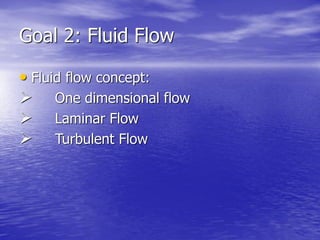
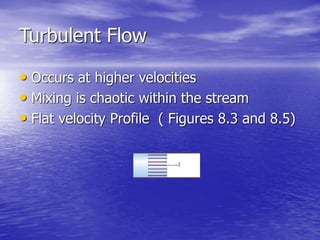
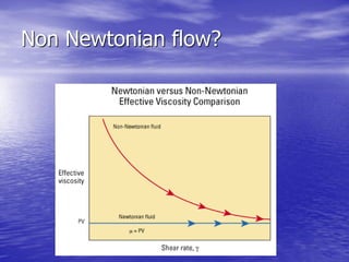
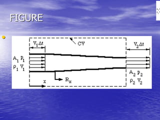
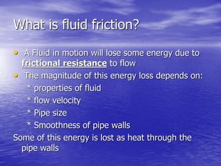
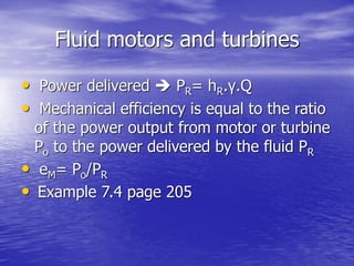
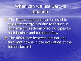
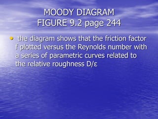
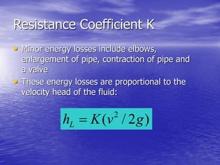
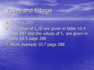
![Separation time of the
two fluids in the decanter
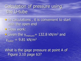
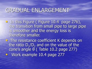
ZA1= [ZA2 – ZT (ρB/ ρA)]/ [1- (ρB/ ρA)]
This equation shows that the position of liquid-
liquid interface depends on:
A) Ratio of densities
B) Elevation of overflow lines
By definition the time of separation is calculated
by: t= (100.μ) / (ρA- ρB)
If ρA≈ ρB → t approaches ∞](https://image.slidesharecdn.com/fluidmechanicsforchrmical-150729010343-lva1-app6892/85/Fluid-mechanics-for-chermical-engineering-students-21-320.jpg)
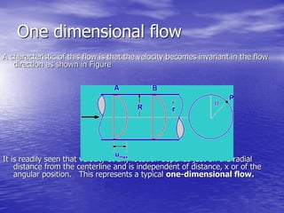
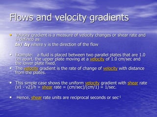
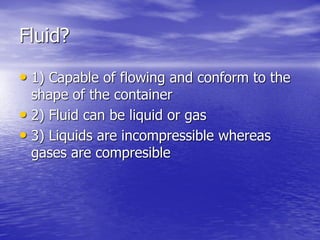
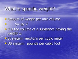
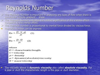
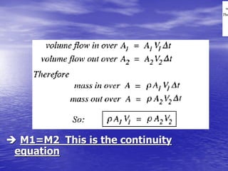
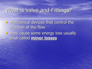
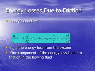
![For Common Fluids
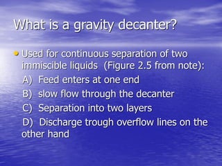
• Water, oil, gasoline, air ……
the shearing stress and rate of
shearing strain ( velocity gradient) can be
related by :
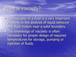
τ= μ ( dv /dy)
Where μ is the dynamic viscosity with unit
as [μ] = N.s/m2 or Pa.s and [τ] = N/m2](https://image.slidesharecdn.com/fluidmechanicsforchrmical-150729010343-lva1-app6892/85/Fluid-mechanics-for-chermical-engineering-students-30-320.jpg)
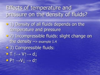
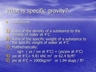
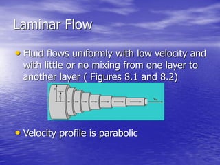
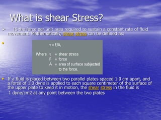
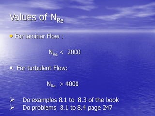
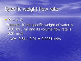
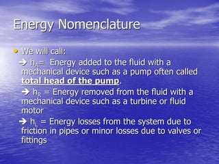
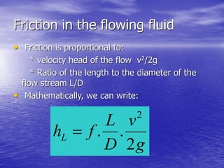
![Dynamic viscosity
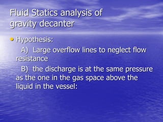
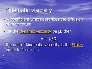
The dynamic viscosity of a fluid is its resistance to
shear or flow and is a measure of the fluids
adhesive/cohesive or frictional properties.
τ= μ ( dv /dy)
Where μ is the absolute or dynamic viscosity with
unit as [μ] = N.s/m2 or Pa.s and [τ] = N/m2](https://image.slidesharecdn.com/fluidmechanicsforchrmical-150729010343-lva1-app6892/85/Fluid-mechanics-for-chermical-engineering-students-32-320.jpg)
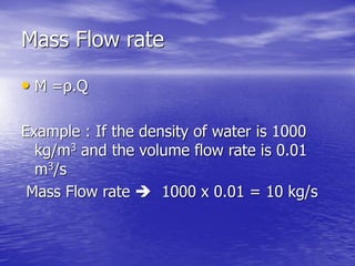
![Volume Flow rate
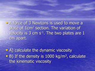
volume of fluid passing trough a
section A per unit time
Q = A.V [Q] = m3/s
Example: If a section is 6.356.10-4m2 and
the velocity equal 3m/s . Calculate Q
Response : Q= 1.907.10-3 m3/s](https://image.slidesharecdn.com/fluidmechanicsforchrmical-150729010343-lva1-app6892/85/Fluid-mechanics-for-chermical-engineering-students-43-320.jpg)
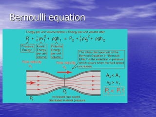
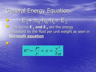
![Bernoulli equation
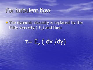
• P1 + ½ ρ v1
2 + ρgh1= P2 + ½ ρ v2
2 + ρgh2
• P2= P1 + ½ ρ[ v1
2 - v2
2] + ρg[h1-h2]
• Calculate v2?
• Continuity equation A1V1= A2V2
• V2 = [A1/ A2] V1
• A1= ¼ ΠD1
2= ¼ x3.14x (25)2= 491 mm2
• A2 = ¼ ΠD2
2= ¼ x3.14x (50)2= 1963 mm2
• V2 = [ 491/1963] x 3 = 0.75 m/s
• ρ = 1000 kg/m3](https://image.slidesharecdn.com/fluidmechanicsforchrmical-150729010343-lva1-app6892/85/Fluid-mechanics-for-chermical-engineering-students-56-320.jpg)
![Bernoulli equation
• P2 = P1 + ½ x1000 x [ 32- 0.752 ] +
1000X 9.81 x (-2)
• P2=P1 – 15.4 kPa
• P2 = 345 – 15.4 = 329.6 kPa](https://image.slidesharecdn.com/fluidmechanicsforchrmical-150729010343-lva1-app6892/85/Fluid-mechanics-for-chermical-engineering-students-57-320.jpg)


This document outlines the goals and topics covered in a fluid mechanics course. The course covers fluid statics, fluid flow concepts, flow of incompressible and compressible fluids, pumping systems, fluid mixing, and fluidization. Key concepts discussed include fluid properties like density, viscosity, compressibility, and pressure. Laminar and turbulent flow regimes are defined. The continuity, Bernoulli, and Reynolds equations are introduced. Example problems are provided to help understand concepts like pressure, viscosity, flow rate calculations, and fluid flow analysis.