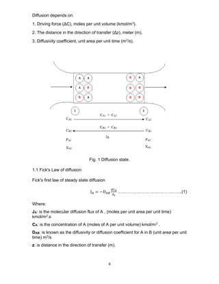
The document outlines fundamentals of mass transfer, focusing on diffusion mechanisms, including molecular and eddy diffusion, and their significance in separation processes. It emphasizes the principles of diffusion driven by concentration gradients and introduces Fick's laws. Additionally, it discusses applications like distillation and absorption in mass transfer operations.
![3
or more different potentials or driving forces, including differences (gradients) of
concentration (ordinary diffusion), pressure (pressure diffusion), temperature
(thermal diffusion), and external force fields (forced diffusion) that act unequally on
the different chemical species present. Pressure diffusion requires a large
pressure gradient, which is achieved for gas mixtures with a centrifuge. Thermal
diffusion columns or cascades can be employed to separate liquid and ga s
mixtures by establishing a temperature gradient across the mixture. More widely
applied is forced diffusion in an electrical field, to cause ions of different charges
to move in different directions at different speeds. In this chapter, only molecular
diffusion caused by concentration gradients is considered, because this is the most
common type of molecular diffusion in commercial separation processes.
Furthermore, emphasis is on binary systems, for which molecular diffusion theory
is simple and applications are relatively straightforward. Multi-component
molecular diffusion, which is important in many applications, is much more
complex than diffusion in binary systems, and is a more appropriate topic for
advanced study using a specialized text.
Molecular diffusion occurs in solids and in fluids that are stagnant or in laminar or
turbulent motion. Eddy diffusion occurs in fluids in turbulent motion. When both
molecular diffusion and eddy diffusion occur, they take place in parallel and are
additive. Furthermore, they take place because of the same concentration
difference (gradient). When mass transfer occurs under turbulent flow conditions,
but across an interface or to a solid surface, conditions may be laminar or nearly
stagnant near the interface or solid surface. Thus, even though eddy diffusion may
be the dominant mechanism in the bulk of the fluid, the overall rate of mass transfer
is controlled by molecular diffusion because the eddy diffusion mechanism is
damped or even eliminated as the interface or solid surface is approached. Mass
transfer of one or more species results in a total net rate of bulk flow or flux in one
direction relative to a fixed plane or stationary coordinate system [1].](https://image.slidesharecdn.com/lecturenotesinmasstransfer-230129175925-2e4e64a2/85/Lecture-Notes-in-Mass-Transfer-3-320.jpg)
![5
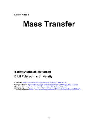
Diffusion with bulk of mass in motion:
Total diffusion = Molecular diffusion + Convection term
Convection term = Eddy diffusion = Molar flux due to convection
Convection term = Concentration . mass transfer velocity = CA . V
Mass transfer velocity (V) =
Mass flux
Concentration
=
NA + NB
CT
=
kmol
m2. s
kmol
m3
=
m
s
Total diffusion = NA = JA + CA . V ………………………(2)
Total diffusion equation in the form of concentration (normally used for liquids):
NA = −DAB
dCA
dz
+
CA
CT
(NA + NB)……………………….(3)
Total diffusion equation in the form of partial pressure (normally used for gases):
NA = −
DAB
RT
dPA
dz
+
PA
PT
(NA + NB)……………………….(4)
Total diffusion equation in the form of mole fraction (used for gases and liquids):
NA = −
DABPT
RT
dXA
dz
+ xA (NA + NB)……………………….(4)
If stagnant diffusion layer, then NB = 0
NA =
DAB
RT
PT
dz
Ln [
PT−PA2
PT−PA1
]…………………………….(5)
1.1.1 Counter diffusion type equimolecular counter diffusion:
When the mass transfer rates of the two components are equal and opposite the
process is said to be one of equimolecular counter diffusion. Such a process
occurs in the case of the box with a movable partition. It occurs also in a distillation
column when the molar latent heats of the two components are the same (λA =
λB).
NA =
DAB
RT
[
PA1−PA2
z2−z1
]…………………………………(6)](https://image.slidesharecdn.com/lecturenotesinmasstransfer-230129175925-2e4e64a2/85/Lecture-Notes-in-Mass-Transfer-5-320.jpg)
![6
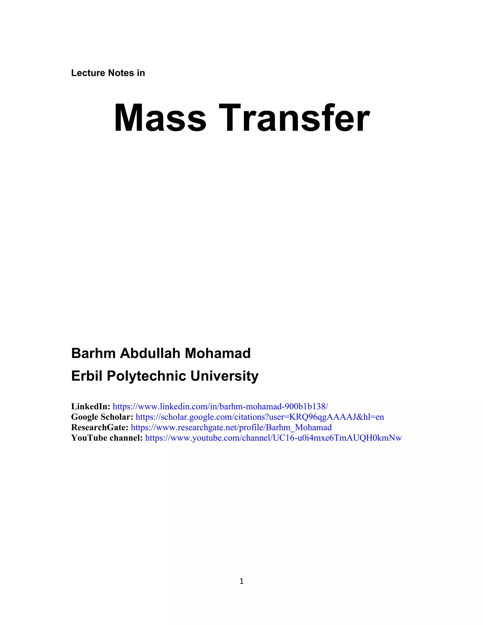
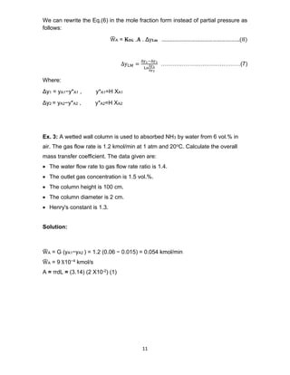
Ex. 1: Ammonia gas is diffusing at a constant rate through a layer of stagnant air
1 mm thick. Conditions are such that the gas contains 50 percent by volume
ammonia at one boundary of the stagnant layer. The ammonia diffusing to the
other boundary is quickly absorbed and the concentration is negligible at that
plane. The temperature is 295 K and the pressure atmospheric, and under these
conditions the diffusivity of ammonia in air is 0.18 cm2/s. Estimate the rate of
diffusion of ammonia through the layer.
Solution:
If the subscripts 1 and 2 refer to the two sides of the stagnant layer and the
subscripts A and B refer to ammonia and air respectively, then the rate of diffusion
through a stagnant layer is given by:
NA =
DAB
RT
PT
dz
Ln [
PT − PA2
PT − PA1
]
PT = 101.3 kPa, PA2 = 0, PA1 = ya.PT = ( 0.5 )101.3 = 50.65 kPa
Δ𝐳 = 𝐳𝟐−𝐳𝟏 = 1 mm = (1)10−3 m
R = 8.314
kj
kmol .K
, T = 295 K and DAB = 0.18
cm2
s
= 1.8 X 10⁻⁵ m2
s
NA =
1.8 X 10⁻⁵
8.314 (295)
101.3
1X10⁻³
Ln [
101.3
101.3−50.65
] = 5.153 X 10⁻³ kmol
m2.s
Ex. 2: In an air-carbon dioxide mixture at 298 K and 202.6 kPa, the concentration
of CO2 at two planes (3 mm) apart are 25 vol.% and 15 vol.% respectively. The
diffusivity of CO2 in air at 298 K and 202.6 kPa is 8.2 X10⁻⁶ m2/s. Calculate the rate
of transfer of CO2 across the two planes, assuming:
a. Equimolecular counter diffusion.
b. Diffusion of CO2 through a stagnant air layer.](https://image.slidesharecdn.com/lecturenotesinmasstransfer-230129175925-2e4e64a2/85/Lecture-Notes-in-Mass-Transfer-6-320.jpg)
![7
Solution:
PA1= yA1 . PT = (0.25) 202.6 = 50.65 kPa
PA2 = yA2 . PT = (0.15) 202.6 = 30.39 kPa
a. Equimolecular counter diffusion:
NA =
DAB
RT
[
PA1−PA2
z2−z1
]
NA =
8.2 X 10⁻⁶
8.314 (298)
[
50.65 − 30.39
3 X 10⁻³
] = 2.23X10⁻⁵ kmol
m2. s
b. Stagnant diffusion.
NA =
DAB
RT
PT
dz
Ln [
PT−PA2
PT−PA1
]
NA =
8.2 X 10⁻⁶
(8.314 )(298 )
202.6
3 X 10⁻³
Ln [
202.6 − 30.39
202.6 − 50.65
] = 2.79 X 10⁻⁵ kmol
m2. s
1.2 Distillation
In distillation (fractionation), a feed mixture of two or more component is separated
into two or more products, including, and often limited to an overhead distillate and
a bottom, whose compositions differ from that of the feed. Most often, the feed is
a liquid or vapor – liquid mixture. The bottoms products is almost always a liquid,
but the distillate may be a liquid or a vapor or both. The separation requires that
(1) a second phase be formed so that both li quid and vapor phases are present
and can contact each other on each stage within a separation column, (2) the
components have different volatilities so that they will partition between the two
phases to different extents, and (3) the two phases can be separated by gravity or
other mechanical means. Distillation differs from absorption and stripping in that
the second phase is created by thermal means (vaporization and condensation)
rather than by the introduction of a second phase that usually contains an
additional component or component does not present in the feed mixture. The](https://image.slidesharecdn.com/lecturenotesinmasstransfer-230129175925-2e4e64a2/85/Lecture-Notes-in-Mass-Transfer-7-320.jpg)
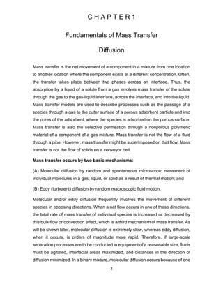
![8
word distillation is derived from Latin word destillare, which means dripping or
trickling down. By at least the sixteenth century, it was known that the extent of
separation could be improved by providing multiple vapor-liquid contacts (stages)
in a so-called Rectificatorium. The term rectification is derived from the Latin words
recte facere , meaning to improve. Modern distillation derives its ability to produce
almost pure products from the use of multistage contacting.
A- Distillation of binary mixtures
Binary Mixture: mixture contains only two components differ in boiling point.
Equipment and Design Consideration Industrial distillation operations are most
commonly conducted in trayed towers, but packed columns are finding increasing
use. Occasionally, distillation columns contain both trays and packing. Types of
trays and packing are identical to those used for absorption and stripping.
A schematic diagram for the distillation column for binary mixture is presented
below [1].
Fig. 2 A schematic diagram for the distillation process.
Factors that influence the design or analysis of a binary distillation operation
include:
1. Feed flow rate, composition, temperature, pressure, and phase condition.
2. Desired degree of separation between two components.](https://image.slidesharecdn.com/lecturenotesinmasstransfer-230129175925-2e4e64a2/85/Lecture-Notes-in-Mass-Transfer-8-320.jpg)
![9
3. Operating pressure (which must be below the critical pressure of the mixture).
4. Vapor pressure drop, particularly for vacuum operation.
5. Minimum reflux ratio and actual reflux ratio.
6. Minimum number of equilibrium stages and act ual number of equilibrium stages
(stage efficiency).
7. Type of condenser (total, partial, or mixed).
8. Degree of sub-cooling, if any, of the liquid reflux.
9. Type of re-boiler (partial or total).
10. Type of contacting (trays or packing or both).
11. Height of the column.
12. Feed entry stage.
13. Diameter of the column.
14. Column internals
1.3 The wetted wall column
The wetted wall column is a small experimental device used to determine the
average mass transfer coefficient (𝐊𝐎𝐆 ). Usually it is (1 - 1.5 inch) in diameter and
one meter long.
Fig. 3 The wetted wall column mass balance [2].](https://image.slidesharecdn.com/lecturenotesinmasstransfer-230129175925-2e4e64a2/85/Lecture-Notes-in-Mass-Transfer-9-320.jpg)
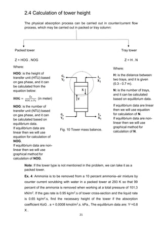
![15
2.3 Design of single stage counter-current flow
absorption tower (packed tower)
Two common gas absorption equipments are packed tower and plate tower. Other
absorption equipments are, namely, spray column, agitated contactor, venture
scrubber, etc. The gas and the liquid phases come in contact in several discrete
stages. Thus, a stage wise contact is there in a plate column. But in packed tower,
the up-flowing gas remains in contact with down-flowing liquid throughout the
packing, at every point of the tower. Therefore, packed tower is known as
“continuous’’ differential contact equipment It is different from the stage-wise
distillation column. In the stage distillation column, the equilibrium in each stage
will vary not in a continuous manner whereas in the packed column the equilibrium
is changed point wise in each axial location [2].
Steps for the design of packed tower:
(A) Selection of solvent
(B) Selection of packing
(C) Calculation of minimum solvent flow rate as well as actual solvent flow rate
(D) Column diameter
(E) Height of column
(F) Design of solvent distributors and redistributors (if needed)
(G)Design of gas distributor, packing support, shell, nozzles, column support
The following items and variables should be known for design of a packed
absorption tower:
(a) Equilibrium data; (b) Gas and liquid flow rates; (c) Solute concentration
in two terminals; (d) Individual and overall volumetric mass transfer
coefficients (Ky𝑎
̅, Kx𝑎
̅, KG𝑎
̅, KL𝑎
̅, etc.).](https://image.slidesharecdn.com/lecturenotesinmasstransfer-230129175925-2e4e64a2/85/Lecture-Notes-in-Mass-Transfer-15-320.jpg)
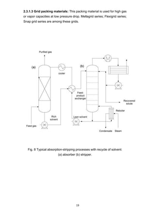
![17
(a) Raschig rings; (b) Lessing rings and (c) Berl saddle
modified Raschig rings
(Cross-partition rings)
Fig.4 First generation dumped or random packing materials [2].
The second-generation random packing materials are mainly (a) Intalox saddle
(modified); (b) Pall ring (modified). Intalox saddle is the modified version of Berl
saddle and offers less friction resistance due to particular shape (two saddles will
never nest). Pall rings are modified version of Raschig rings. These are shown in
Figure 5.
(a) Intalox saddle (modified) (b) Pall ring (modified)
Fig. 5 Second generation dumped or random packing materials [2].
The third-generation random packing materials are numeral; (a) Intalox Metal
Tower Packing (IMTP); (b) Nutter ring; (c) Cascade Mini-Ring (CMR); (d) Jaeger
Tripac; (e) Koch Flexisaddle; (f) Nor-Pac; (g) Hiflow ring, etc. These are shown in
Figure 6.](https://image.slidesharecdn.com/lecturenotesinmasstransfer-230129175925-2e4e64a2/85/Lecture-Notes-in-Mass-Transfer-17-320.jpg)
![18
Fig. 6 Third generation dumped or random packing materials [2].
2.3.1.2 Structured packing materials: These materials are used widely as
packing materials in packed tower due to low gas pressure drop and improved
efficiency. Corrugated metal sheet structured packing and Wire mesh structured
packing materials are widely used in the industries. These include Mellapak,
Flexipak, Gempak, Montz and MaxPak. These are shown in Figure 7.
Fig. 7 Snapshots of some structured packing materials [2].
Mellapak Flexipak Montez corrugated
metal sheet
Wire mesh
packing
(e) Koch Flexisaddle (f) Nor-Pac (g) Hiflow ring
(a) Intalox metal
tower packing
(IMTP)
(b) Nutter ring (c) Cascade
Mini ring
(CMR)
(d) Jaeger Tripac](https://image.slidesharecdn.com/lecturenotesinmasstransfer-230129175925-2e4e64a2/85/Lecture-Notes-in-Mass-Transfer-18-320.jpg)
![20
Fig. 9 Industrial gas absorption processes [2].
Table 1 Examples of industrial gas absorption processes [2].
Industry Component to be
removed
Solvent
Wood industry (Kraft
and sulphite methods)
Glass production
SO2 Water
Carbon industry CO2 Water, basic liquids
(K2CO3) or other
solvents (acetone, etc.)
H2SO4 Production SO3 H2SO4 (98%)
HNO3 Production NOX Water (absorption and
chemical reaction)
HCl Production HCL Water
Explosive manufacture NOX Water](https://image.slidesharecdn.com/lecturenotesinmasstransfer-230129175925-2e4e64a2/85/Lecture-Notes-in-Mass-Transfer-20-320.jpg)
![22
Solution:
y2 = (1−𝑟𝑒𝑐𝑜𝑣𝑒𝑟𝑦) y1 = (1−0.99) (0.1) = 0.001
Convert mole fraction to mole ratio:
𝑦1 =
𝑦1
1 − 𝑦1
=
0.1
1 − 0.1
= 0.11
𝑦2 =
𝑦2
1−𝑦2
=
0.001
1−0.001
= 0.001
We can see that at low conc. (mole ratio = mole fraction):
The gas mole flux, G
̅ =
Gas mass flux
Average gas molecular weight
=
0.95
[(0.1) (17) +(0.99) (29)]
=
0.0312
kmol
m2.s
The liquid mole flux, L
̅ =
Liquid mass flux
Average liquid molecular weight
=
0.65
18
= 0.0361
kmol
m2.s
The mole flux of the inert gas, G
̅𝐬 = G
̅ (𝟏−𝐲𝟏) = (0.0312) (1−0.11) = 0.027
kmol
m2.s
The mole flux of the inert liquid, L
̅s = L
̅ (𝟏−𝐱𝟐 )= (0.0361) (1−0) = 0.0361
kmol
m2.s
Therefore, for pure solvent: L
̅s = L
̅
𝐇𝐎𝐆 =
G
̅s
KOG . a . PT
=
0.027
( 0.0008) (101.3)
= 0.333 m
Since the equilibrium is linear:
∅ =
mGs
̅̅̅̅
Ls
̅̅̅
=
(0.8) (0.027)
(0.0361)
= 0.598
NOG =
1
(1 − ∅)
ln [
(1 − ∅)y1 + ∅y2
(1 − ∅)y2 + ∅y2
]
=
1
(1 − 0.598)
ln [
(1 − 0.598)0.1 + 0.598(0.001)
(1 − 0.598)0.001 + 0.598(0.001)
] = 9.2
Z = HOG . NOG = (0.333)(9.2) = 3.06 m](https://image.slidesharecdn.com/lecturenotesinmasstransfer-230129175925-2e4e64a2/85/Lecture-Notes-in-Mass-Transfer-22-320.jpg)
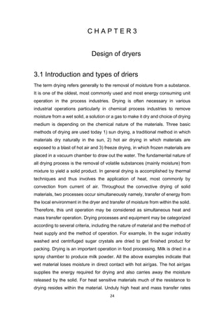
![23
2.5 Mass transfer coefficient from empirical
correlation
Several workers have measured the rate of transfer from a liquid flowing down
the inside wall of a tube to a gas passing counter currently upwards. Gilliland
and Sherwood vaporized a number of liquids including water, toluene, aniline
and propyl, amyl and butyl alcohols into an air stream flowing up the tube in
order to measure the individual mass transfer coefficient (kg). Gilliland and
sherwood used the empirical relation below to measure the individual mass
transfer coefficient (Kg) and this relation in forms of dimensionless [3].
Ex. 5: Calculate the gas film coefficient for the absorption of sulpher dioxide
from a dilute mixture with air in a wetted wall column using Gilliland and
Sherwood correlation for wetted wall column for the following data:
• Gas velocity = 2.5 m/s.
• Gas temperature = 293 K.
• Gas viscosity = 1.78 X 10⁻⁵ N.s/m2.
• Gas density = 1.22 kg/m3.
• Gas diffusivity = 1.22 X 10⁻⁵ m2/s.
• Inside column diameter = 25 mm.
Solution:
Sh = 0.023 (Re) 0.83 (Sc) 0.44
Sh =
Kg. d
D
= kg =
25 X 10−3
1.22 X 10−5
= 2049 kg
Re =
ρud
μ
=
(1.22)(2.5)(25 X 10−3
)
1.78 X 10−5
= 4283.7
Sc =
μ
ρ. D
=
1.78 X 10⁻⁵
(1.22)1.22 X 10−5
= 1.1959
2049 kg = 0.023 (4283.7) 0.83 (1.1959) 0.44
Kg = 0.545
m
s](https://image.slidesharecdn.com/lecturenotesinmasstransfer-230129175925-2e4e64a2/85/Lecture-Notes-in-Mass-Transfer-23-320.jpg)
![25
applied at the surface only result in overheating or over drying of the surface
layer resulting in quality problems without major increase in the drying kinetics.
The rate of migration of the moisture from within the solid to the evaporation
front often controls the overall drying rate. Therefore, drying may be defined as
an operation in which the liquid, generally water, present in a wet solid is
removed by vaporization to get a relatively liquid free solid product. Drying of a
solid does not demand or ensure complete removal of the moisture. Sometimes
it is desirable to retain a little moisture in the solid after drying. Dryer and drying
process selection for a specific operation is a complex problem, and many
factors have to be taken into account. Though, the overall selection and design
of a drying system for a particular material is dictated by the desire to achieve
a favorable combination of a product quality and process economics. In general,
with respect to the rate and total drying time, dryer performance is dependent
on the factors such as air characteristics, product characteristics, equipment
characteristics. But despite the many commercially available drying techniques
at present most dehydrated products (i.e., fruits and vegetables) are still
produced by the method of hot air drying. Because this is regarded as the
simplest and most economical. There are other water/liquid removal processes
such as filtration, settling, centrifugation, supercritical extraction of water from
gels etc. In all these operations liquid is removed by mechanical means, but a
considerable amount of liquid is still retained in the solid. This residual liquid
can be removed by drying. One such example is the production of condensed
milk involves evaporation, but the production of milk powder involves drying.
The phase change and production of a soild phase as end product are essential
features of the drying process. Drying is an essential operation in chemical,
agricultural, biotechnology, food, polymer, pharmaceutical, pulp and paper,
mineral processing, and wood processing industries [3].
3.2 Physical mechanism of drying
Drying does not mean only removal of the moisture but during the process,
physical structure as well as the apperance has to be preserved. Drying is
basically governed by the principles of transport of heat and mass. When a
moist solid is heated to an appropriate temperature, moisture vaporizes at or
near the solid surface and the heat required for evaporating moisture from the
drying product is supplied by the external drying medium, usually air or a hot](https://image.slidesharecdn.com/lecturenotesinmasstransfer-230129175925-2e4e64a2/85/Lecture-Notes-in-Mass-Transfer-25-320.jpg)
![26
gas. Drying is a diffusional process in which the transfer of moisture to the
surrounding medium takes place by the evaporation of surface moisture, as
soon as some of the surface moisture vaporizes, more moisture is transported
from interior of the solid to its surface. This transport of moisture within a solid
takes place by a variety of mechanisms depending upon the nature and type of
the solid and its state of aggregation. Different types of solids may have to be
handled for drying crystalline, granular, beads, powders, sheets, slabs, filter-
cakes etc. The mechanism of moisture transport in different solids may be
broadly classified into (i) transport by liquid or vapour diffusion (ii) capillary
section, and (iii) pressure induced transport. The mechanism that dominates
depends on the nature of the solid, its pore structure and the rate of drying.
Different mechanisms may come into play and dominate at different stages of
drying of the same material.
The following term are commonly used in designing of drying systems.
Moisture content of a substance which exerts as equilibrium vapour pressure
less than of the pure liquid at the same temperature is refered to as bound
moisture.
Moisture content of the solid which exters an equillibrium vapour pressure equal
to that of pure liquid at the given temperature is the unbound moisture.
The moisture content of solid in excess of the equilibrium moisture content is
refered as free moisture. During drying, only free moisture can be evporated.
The free moisture content of a solid depends upon the vapour concentration in
the gas.
The moisture contents of solid when it is in equilibrium with given partial
pressure of vapour in gas phase is called as equilibrium moisture content.
Similalry, the moisture content at which the constant rate drying peroid ends
and the falling rate drying period starts is called critical moisture content.
During the constant rate drying period, the moisture evporated per unit time
per unit area of drying surface remains constant and in falling rate drying
period the amount of moisture evporated per unit time per unit area of drying
surface continuously decreases [3].](https://image.slidesharecdn.com/lecturenotesinmasstransfer-230129175925-2e4e64a2/85/Lecture-Notes-in-Mass-Transfer-26-320.jpg)
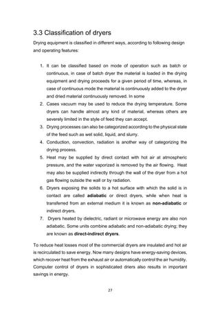
![28
3.4 Drying equipment
3.4.1 Batch type dryers
3.4.1.1 Tray dryer
Schematic of a typical batch dryer is shown in figure 11. Tray dryers usually
operate in batch mode, use racks to hold product and circulate air over the
material. It consists of a rectangular chamber of sheet metal containing trucks
that support racks. Each rack carries a number of trays that are loaded with the
material to be dried. Hot air flows through the tunnel over the racks. Sometimes
fans are used to on the tunnel wall to blow hot air across the trays. Even baffles
are used to distribute the air uniformly over the stack of trays. Some moist air is
continuously vented through exhaust duct; makeup fresh air enters through the
inlet. The racks with the dried product are taken to a tray-dumping station.
Fig. 11 Tray dryer [3].
These types of dryers are useful when the production rate is small. They are
used to dry wide range of materials but have high labor requirement for
loading and unloading the materials and are expensive to operate. They find
most frequent application for drying valuable products. Drying operation in
case of such dryers is slow and requires several hours to complete drying of
one batch. With indirect heating often the dryers may be operated under
vaccum. The trays may rest on hollow plates supplied with steam or hot water
or may themselves contain spaces for a heating fluid. Vapour from the solid
may be removed by an ejector or vacuum pump. Freeze-drying involves the
sublimation of water from ice under high vacuum at temperatures well below
0oC. This is done in special vacuum dryers for drying heat-sensitive products.](https://image.slidesharecdn.com/lecturenotesinmasstransfer-230129175925-2e4e64a2/85/Lecture-Notes-in-Mass-Transfer-28-320.jpg)
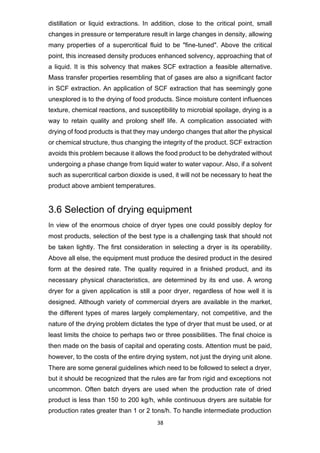
![29
3.4.1.2 Pan dryer
The atmospheric pan drier has a jacketed round pan in which a stirrer or mill
revolves slowly, driven from below. The slow-moving stirrer exposes fresh
surfaces and thereby raises the rate of evaporation and, hence, of drying. The
pan drier is a batch machine and is limited to small batches. Pan driers may
be used first to evaporate a solution to its crystallizing concentration and then
can function as a crystallizer by sending cold water instead of steam into the
jacket. The effect of the stirrer during crystallization prevents the growth of
large crystals and promotes formation of small, uniform crystals. The mother
liquor is then drained off and the crystals dried in the same apparatus [3].
Fig. 12 Pan dryer [3].
3.4.1.3 Agitated vacuum dryer
The agitated vacuum dryer is one of the most versatile in the range and is
similar in principle to a pan dryer. The dryer essentially consists of a jacketed
cylindrical vessel arranged for hot water, steam or a suitable thermal fluid flow
through the jacket for heating. Doors are provided on the shell, at the top for
loading the feed material and at the bottom for discharging. The dryers are
available in variety of sizes. The entire drying chamber is well machined to
insure small clearance with the agitator blade. Thus, ensures proper shuffling
of the material and avoids localized overheating. Due to the agitation of the
product in the agitated vacuum dryer the drying time is substantially reduced.](https://image.slidesharecdn.com/lecturenotesinmasstransfer-230129175925-2e4e64a2/85/Lecture-Notes-in-Mass-Transfer-29-320.jpg)
![30
Fig. 13 Agitated pan dryer [3].
A choice of the agitator design which can be arranged with or without heating
depends on the material characteristics and process requirements. While
designing the shell one has to consider the external pressure and the shaft
designing includes fatigue consideration. Designing the impeller needs
consideration of characteristics of the material before and after drying [3].
3.4.2 Continuous dryer
3.4.2.1 Rotary dryer
The rotary drier is basically a cylinder, inclined slightly to the horizontal, which
may be rotated, or the shell may be stationary, and an agitator inside may
revolve slowly. In either case, the wet material is fed in at the upper end, and
the rotation, or agitation, advances the material progressively to the lower end,
where it is discharged. Figure 14 shows a direct heat rotary drier. Typical
dimensions for a unit like this are 9 ft diameter and 45 ft length. In direct heat
revolving rotary driers, hot air or a mixture of flue gases and air travels through
the cylinder. The feed rate, the speed of rotation or agitation, the volume of](https://image.slidesharecdn.com/lecturenotesinmasstransfer-230129175925-2e4e64a2/85/Lecture-Notes-in-Mass-Transfer-30-320.jpg)
![31
heated air or gases, and their temperature are so regulated that the solid is
dried just before discharge.
Fig. 14 Counter current direct heat rotary dryer [4].
The shell fits loosely into a stationary housing at each end. The material is
brought to a chute that runs through the housing; the latter also carries the
exhaust pipe. The revolving shell runs on two circular tracks and is turned by
a girth gear that meshes with a driven pinion. The inclination is one in sixteen
for high capacities and one in thirty for low ones. As the shell revolves, the
solid is carried upward one-fourth of the circumference; it then rolls back to a
lower level, exposing fresh surfaces to the action of the heat as it does so.
Simple rotary driers serve well enough when fuel is cheap. The efficiency is
greatly improved by placing longitudinal plates 3 or 4 in. wide on the inside of
the cylinder. These are called lifting flights. These carry part of the solid half-
way around the circumference and drop it through the whole of a diameter in
the central part of the cylinder where the air is hottest and least laden with
moisture. By bending the edge of the lifter slightly inward, some of the material
is delivered only in the third quarter of the circle, producing a nearly uniform
fall of the material throughout the cross section of the cylinder. The heated air
streams through a rain of particles. This is the most common form of revolving
rotary cylinder. It has high capacity, is simple in operation, and is continuous.](https://image.slidesharecdn.com/lecturenotesinmasstransfer-230129175925-2e4e64a2/85/Lecture-Notes-in-Mass-Transfer-31-320.jpg)
![32
3.4.2.2 Drum dryer
In drum dryers (Figure 15) a liquid containing dissolved solids or slurry carrying
suspended solids forms a thin layer on the outside surface of a large rotating
drum. For a single drum unit thickness of the film can be controlled by an
adjustable scraping blade. In case of a double drum unit thickness can be
controlled by the gap between the drums (Figure 16). A gas, normally air may
be blown over the surface for rapid removal of moisture. The rotation of the
drum adjusted so that all of the liquid is fully vaporized, and a dried deposit
can be scrapped off with the help of flexible or adjustable knife. This type of
dryer mainly handles the materials that are too thick for a spray dryer and too
thin for a rotary dryer. The solid collects on an apron in front of the knife and
rolls to a container or to a screw conveyor. The operation of the drum drier is
continuous. The drum is rotated continuously by a gear driven by a pinion that
receives its motion through a belt, a chain, or a reduction gear from. The speed
of the drum may be regulated by a variable-speed drive to adopt the speed to
any slight variation in the feed quality. The speed of the drum regulated
depending upon the nature of materials (i.e wet or dry), if the product material
is wet/dry quite a distance before the knife is reached, the speed should be
decreased/increased. The design of the components is similar to that of drum
filter. The knife may be held just against the surface. It may be brought closer
by turning the adjusting wheels. The knife supports may be turned through
part of a circle so that the angle of the blade of the knife relative to the drum
surface may be selected for the greatest shearing effect. In recent years,
double drum dryers have replaced single drum dryer in several applications
(Figure 15), due to their more efficient operation, wide range of products and
high production rates [4].](https://image.slidesharecdn.com/lecturenotesinmasstransfer-230129175925-2e4e64a2/85/Lecture-Notes-in-Mass-Transfer-32-320.jpg)
![33
Fig. 15 Single drum dryer [4].
Fig. 16 Double drum dryer [4].](https://image.slidesharecdn.com/lecturenotesinmasstransfer-230129175925-2e4e64a2/85/Lecture-Notes-in-Mass-Transfer-33-320.jpg)
![34
3.4.2.3 Flash dryer
The flash driers (Figure 17), also called pneumatic dryers, are similar in their
operating principle to spray dryer. The materials that are to be dried (i.e. solid
or semisolid) are dispersed in finely divided form in an upward flowing stream
of heated air. These types of dryers are mainly used for drying of heat sensitive
or easily oxidizable materials. The wet materials that are too dried can be
passed into a high-temperature air stream that carries it to a hammer mill or
high-speed agitator where the exposed surface is increased. The drying rate is
very high for these dryers (hence the term flash dryers), but the solid
temperature does not rise much because of the short residence time. A flash
dryer is not suitable for particles which are large in size or heavy particles. The
special advantage of this type of dryer is that no separate arrangement is
required for transporting the dried product. The fine particles leave the mill
through a small duct to maintain the carrying velocities (drying gas) and reach
a cyclone separator. A solid particle takes few seconds to pass from the point
of entry into the air stream to the collector. The inlet gas temperature is high
and varies from 650oC to 315oC, for example, in 2 seconds, or from 650oC to
175oC in 4 seconds. The thermal efficiency this type of dryer is generally low.
A material having an initial moisture content of 80 % may be reduced to 5 or 6
% in the dried product [4].
Fig. 17 Flash dryer [4].](https://image.slidesharecdn.com/lecturenotesinmasstransfer-230129175925-2e4e64a2/85/Lecture-Notes-in-Mass-Transfer-34-320.jpg)
![35
3.4.2.4 Fluidized bed dryer
Fluidized bed dryer consists of a steel shell of cylindrical or rectangular cross
section. A grid is provided in the column over which the wet material is rests. In
this type of dryer, the drying gas is passed through the bed of solids at a velocity
sufficient to keep the bed in a fluidized state. Mixing and heat transfer are very
rapid in this type of dryers. The dryer can be operated in batch or continuous
mode (Figure 18). Fluidized bed dryer is suitable for granular and crystalline
materials. If fine particles are present, either from the feed or from particle
breakage in the fluidized bed, there may be considerable solid carryover with
the exit gas and bag filters are needed for fines recovery. The main advantage
of this type of dryer are rapid and uniform heat transfer, short drying time, good
control of the drying conditions.
In case of rectangular fluid-bed dryers separate fluidized compartments are
provided through which the solids move in sequence from inlet to outlet. These
are known as plug flow dryers; residence time is almost the same for all
particles in the compartments. But the drying conditions can be changed from
one compartment to another, and often the last compartment is fluidized with
cold gas to cool the solid before discharge [4].
Fig. 18 Continuous fluidized bed dryer [4].](https://image.slidesharecdn.com/lecturenotesinmasstransfer-230129175925-2e4e64a2/85/Lecture-Notes-in-Mass-Transfer-35-320.jpg)
![36
3.4.2.5 Screen conveyor dryers
Screen conveyor dryer is also called a direct heat continuous type dryer. The
solid to be dried are fed on to endless, perforated, conveyor belt through which
hot air is forced. The belt is housed in a long rectangular drying chamber or
tunnel (Figure 19). The chamber is divided into series of separate sections,
each with its own fan and air heater. Air may be recirculated through and vented
from each section separately or passed from one section to another counter
current to the solid movement. The solid is carried through the tunnel and
discharged at the opposite end. In order to prevent the higher flow rate of hot
air through thinner regions of the bed a uniform feeding rate and distribution of
the material over the conveyor is necessary. Coarse granular, flakey, or fibers
materials can be dried by through circulation without any pretreatment and
without loss of material through the screen. High drying rate can be achieved
with good product quality control. Thermal efficiency of this type of dryer is high
and with steam heating, the steam consumption for heating the drying gas can
be as low as 1.5 kg per kg of water evaporated. Only disadvantage of this type
of dryer are high initial cost and high maintenance cost due to the mechanical
belt.
Fig. 19 Screen conveyor dryer [4].](https://image.slidesharecdn.com/lecturenotesinmasstransfer-230129175925-2e4e64a2/85/Lecture-Notes-in-Mass-Transfer-36-320.jpg)
![37
3.5 Novel drying technologies
Newer technologies focus on saving in energy consumption that result in
considerable overall improvement in energy efficiency. In addition, the final
quality of the product is greatly influenced by the drying technique and strategy.
A brief overview of some novel drying techniques is given below:
3.5.1 Microwave drying
Microwave heating is a direct drying method. High-frequency radio waves are
utilized in microwave drying. A high frequency generates the waves and wave
channel guides them into an oven that is designed to prevent the waves from
leaving the chamber. In microwave drying, heat is generated by directly
transforming the electromagnetic energy into kinetic molecular energy, thus the
heat is generated deep within the material to be dried. Selection of proper
wavelength is necessary to ensure thorough penetration into the material. Apart
from these, other parameters such as material type and depth of material being
exposed also affect the penetration. Therefore, selection of proper wavelengths
and dehydration condition for each product is selected individually.
This type of heating is instantaneous, uniform and penetrating throughout the
material, which is a great advantage for the processing of pharmaceutical
compounds. In case of microwave drying the waves bounce from wall to wall,
until the product absorbs eventually all of the energy, generating heat within the
material, resulting in dehydration. Vapour from the liquid evaporating inside the
product is emitted through the pore structure of the solid material‟s macro-
capillary system, resulting in a high drying rate. This type of dryer is highly
efficient and power utilization efficiencies are generally greater than 70 %.
Important commercial aspects of this dryer include the ability to maintain colour,
moisture and quality of the natural food [4].
3.5.2 Supercritical fluid extraction and its application
to drying
The supercritical fluid (SCF) is a substance at a temperature and pressure
above its critical point. It can effuse through solids like a gas, and dissolve
materials like a liquid. Supercritical fluids possess unique properties that enable
them to extract components selectively from a mixture. This ability has been
investigated as an alternative to currently used separation processes such as](https://image.slidesharecdn.com/lecturenotesinmasstransfer-230129175925-2e4e64a2/85/Lecture-Notes-in-Mass-Transfer-37-320.jpg)
![39
rates other factors must be considered [4].
The dryer must also operate reliably, safely, and economically. Operation and
maintenance costs must not be excessive; pollution must be controlled; energy
consumption must be minimized. As with other equipment these requirements
may be conflict with one another, and a compromise needs to be reached in
finding the optimum dryer for a given service. As far as the drying operation
itself is concerned, adiabatic dryers are generally less expensive than non-
adiabatic dryers, in spite of the lower thermal efficiency of adiabatic units.
Unfortunately, there is usually a lot of dust carry over from adiabatic dryers, and
these entrained particles must be removed from the drying gas. Elaborate
particle-removal equipment may be needed, equipment that may cost as much
as the dryer itself. This often makes adiabatic dryers less commercially
attractive than a “buttoned-up” non-adiabatic system in which little or no gas is
used.](https://image.slidesharecdn.com/lecturenotesinmasstransfer-230129175925-2e4e64a2/85/Lecture-Notes-in-Mass-Transfer-39-320.jpg)
![40
3.6 Design consideration of driers
3.6.1 Design of dryer
Design of a rotary dryer only on the basis of fundamental principle is very difficult.
Few of correlations that are available for design may not prove to be satisfactory
for many systems. The design of a rotary dryer is better done by using pilot plant
test data and the full-scale operating data of dryer of similar type if available,
together with the available design equations. A fairly large number of variables
are involved such as solid to be dried per hour, the inlet and exit moisture
contents of the solid, the critical and equilibrium moisture contents, temperature
and humidity of the drying gas. The design procedure based on the basic
principles and available correlations is discussed below. In this case we assume
that the solid has only unbound moisture and as shown in Figure 20 in stage II
the solid is at the wet bulb temperature of the gas [4].
Fig. 20 Temperature profile for solid and gas in a counter current
rotary dryer [4].
1. Heat losses from dryer surfaces are neglected.
2. Once the capacity of the dryer is known, the drying gas flow rate, its
temperature and humidity are decided considering a number of factors.
And the following moisture & enthalpy balances need to be satisfied.
Gs (Y1 - Y2) = Ms (X1 – X2)
Gs (Hg2 – Hg1) = Ms (HS2 – Hs1) …………………….. (8)
Where;
Gs = flow rate of air (dry basis, kg/h)
Ms = flow rate of solid (kg/h, dry basis)
Hs = humidity of air (kg/H2O/kg dry air)](https://image.slidesharecdn.com/lecturenotesinmasstransfer-230129175925-2e4e64a2/85/Lecture-Notes-in-Mass-Transfer-40-320.jpg)
![42
Fig. 21 Scanning electron microscopy images of the cross section of a
flat sheet: (a) Hollow fiber (b) Membrane prepared from a modified poly-
ketone [4].
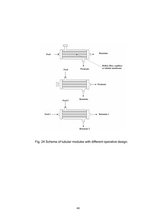
Tubular membranes can be distinguished–in hollow fibers (fiber diameter below
0.5 mm), capillary (fiber diameter comprised between 0.5 and 10 mm) and
tubular (fiber diameter > 10mm).
For applications on large scale, membranes are efficiently packed in small and
compact Plate-and -frame modules make use of flat-sheet membranes (in
sandwich configuration) separated by support plates. These modules have low
packing densities and are correspondingly expensive; they are for examples
used to produce potable water in small-scale applications.
Spiral-wound modules allow the efficient packaging of flat-sheet membrane in a
convenient cylindrical form. They consist in an arrangement of two rectangular
membranes placed back-to-back and sealed on three sides. They are rolled
around a collector tube connected to the fourth side which remains open. The
solution to be treated is brought to one end of this cylinder and the product
circulates between both membranes to the collector tube. A spiral-wound module
is contained in a pressure vessel assembly, consisting of a cylindrical housing
for the modules, a plumbing [4].](https://image.slidesharecdn.com/lecturenotesinmasstransfer-230129175925-2e4e64a2/85/Lecture-Notes-in-Mass-Transfer-42-320.jpg)
![43
Fig. 22 Scheme of a plate and frame membrane module [4].
Fig. 23 Scheme of a spiral wound module [4].](https://image.slidesharecdn.com/lecturenotesinmasstransfer-230129175925-2e4e64a2/85/Lecture-Notes-in-Mass-Transfer-43-320.jpg)