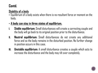
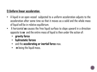
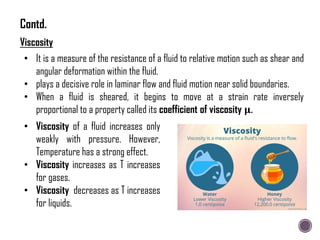
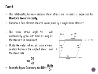
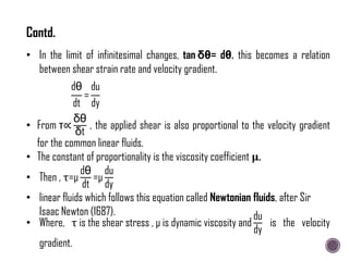
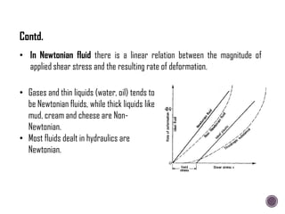
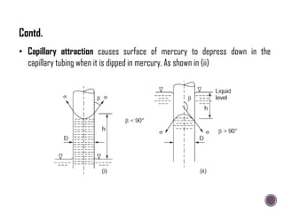
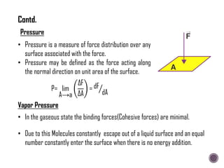
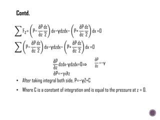
The document discusses the fundamental concepts of fluid mechanics, including the definitions and properties of fluids, including density, viscosity, and surface tension. It outlines the branches of fluid mechanics, specifically hydraulics, and describes the applications and significance of these properties in engineering, such as fluid flow, pressure variation, and hydrostatics. Key equations and principles like Pascal's Law and the relationship between shear stress and viscosity are also covered.


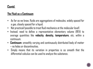
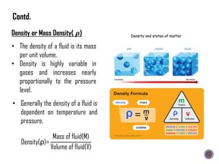
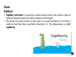
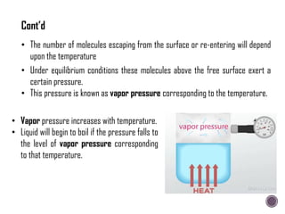
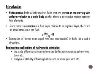
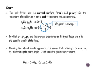
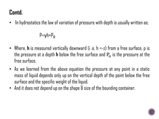
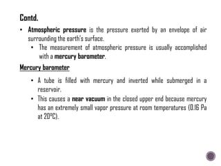
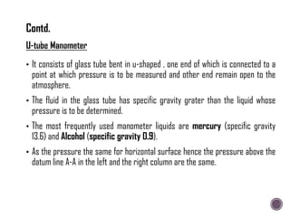
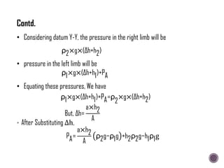
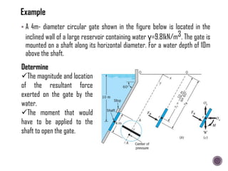
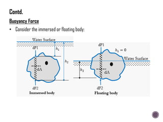
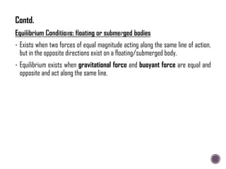
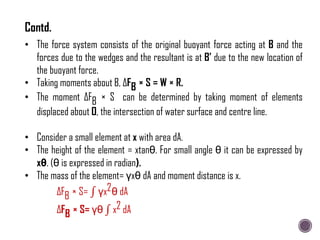
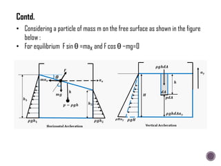
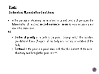
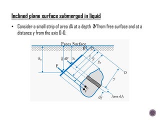
![ An inverted U-tube manometer is fitted between two pipes as shown in
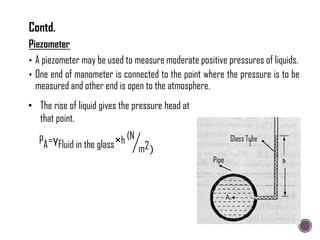
Figure. Determine the pressure at E if PA = 0.4 bar or 40kPa (gauge).
PB = PA – [(0.9 × 1000) × 9.81 × 1.2]
= 40000 – [(0.9 × 1000) × 9.81 × 1.2]
= 29,405.2 N/m2
PC = PB – [(0.9 × 1000) × 9.81 ×
0.8] = 22342 N/m2
PD =PC = 22342 N/m2
PE = PD + [1000 × 9.81 × 0.8] =
30190 N/m2 = 30.19 kPa (gauge)](https://image.slidesharecdn.com/hydraulicsintroductionhydrostatics-240213132939-e6ac6d7e/85/Hydraulics-Introduction-Hydrostatics-pdf-61-320.jpg)
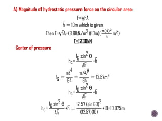
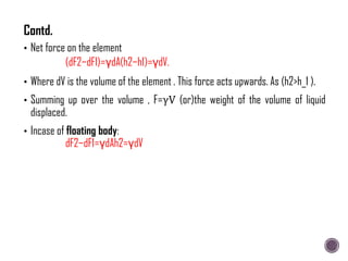
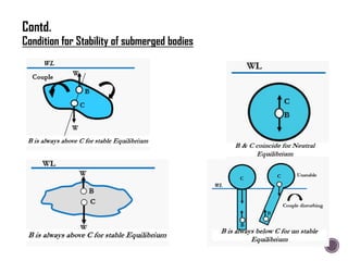
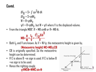
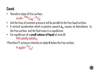
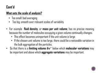
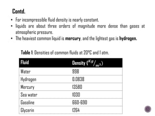
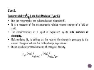
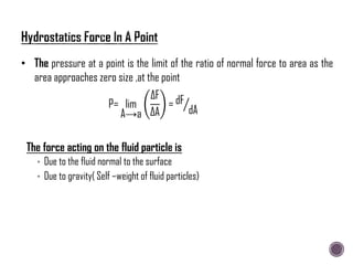
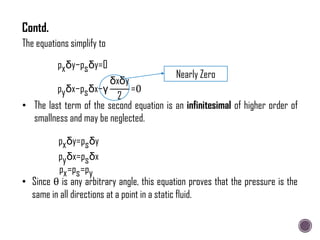
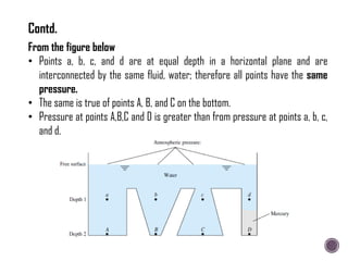
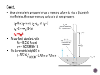
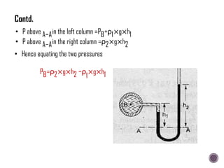
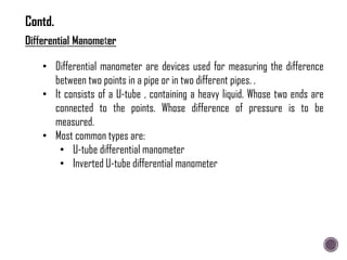
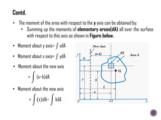
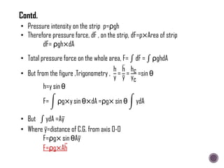
![Starting from level in chamber A and level 3 as datum
PB=PA+ y1+∆y γ1 + y2+y3−∆y ×y2 − 2y3×γ3 − y2−y3+∆y ×γ2 −{(y1−∆y)×γ1}
PB =PA −{ 2×y3× γ3−γ2 +2∆y×(γ2−γ1)}
• Let pressure PA>PB and let it cause a depression of ∆y in chamber A. The
fluid displaced goes into the U tube limb of area a.
• The displacement in the limb will therefore by (y × A/a) which becomes
better readable.
• There fore the displaced volume of fluid:
ay3=∆yA
∆y= (a A)y3
PA−PB=2×y3×[γ3−γ2×{1−( a A)}]
• Very often γ1 is small (because gas is generally the medium) and the last
term is negligible. So
Contd.](https://image.slidesharecdn.com/hydraulicsintroductionhydrostatics-240213132939-e6ac6d7e/85/Hydraulics-Introduction-Hydrostatics-pdf-63-320.jpg)
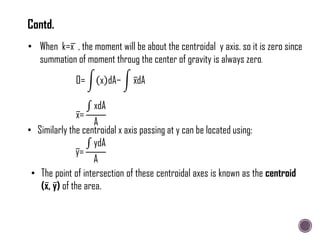
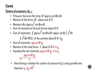
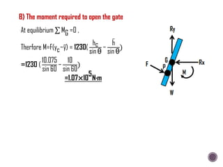
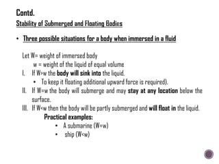
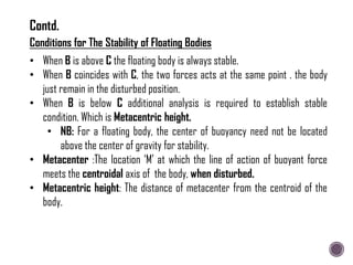
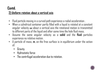
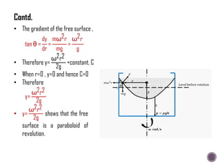
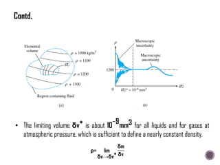
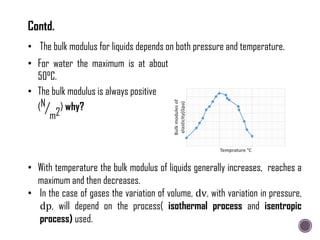
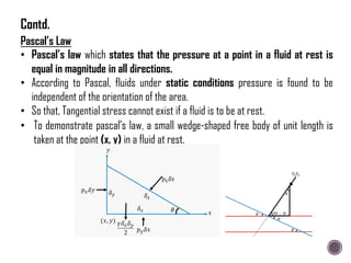
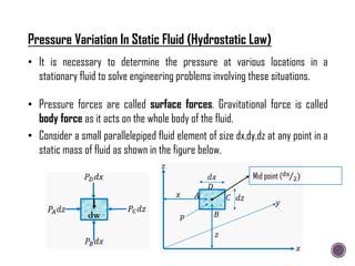
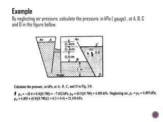
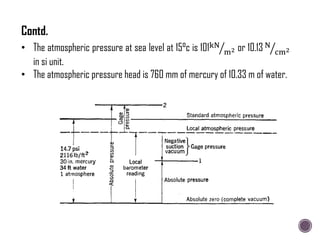
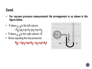
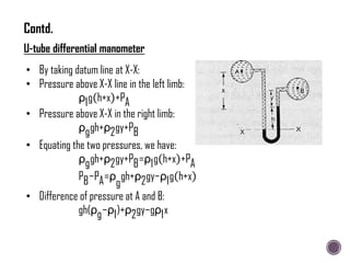
![hc
sin θ
=
ρg sin θ
ρgAh
[IG+Ay
2
]
hc=
sin2 θ
Ah
[IG+Ay
2
]
But
h
y
= sin θ
hc=
sin2 θ
Ah
[IG+
Ah
2
sin2 θ
]
hc=
IG sin2 θ
Ah
+h
Contd.](https://image.slidesharecdn.com/hydraulicsintroductionhydrostatics-240213132939-e6ac6d7e/85/Hydraulics-Introduction-Hydrostatics-pdf-82-320.jpg)