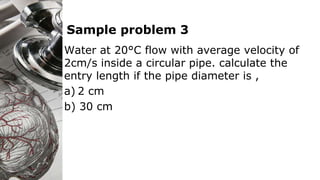
Here are the key steps to solve this problem:
1) Given: Flow rate Q = 34 Lps = 0.034 m3/s
Pipe diameter D = 0.1 m
Water properties at 50°F: ρ = 1000 kg/m3, μ = 1.12 centipoise
2) Calculate Reynolds number: Re = ρVD/μ
= (1000 kg/m3)×(0.034 m3/s)×(0.1 m)/(1.12×10-3 kg/m-s)
= 3000
3) The flow is turbulent for Re > 2000.
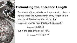
4) Entrance length for turbulent flow: Lh = 4.4D(