SlideShare a Scribd company logo
TOM
Yatin Kumar Singh Page 1
1.1 Introduction
A mechanism is a set of machine elements or components or parts arranged in a specific order to produce a
specified motion. The machine elements or components are considered rigid or resistant bodies that do not
deform under the action of forces. Resistant bodies are bodies that do not suffer appreciable distortion or
change in physical form due to forces acting on them, e.g. springs, belts, and fluids. Elastic bodies are also
resistant bodies. They are capable of transmitting the required forces with negligible deformation. Rigid
bodies are bodies that do not deform under the action of forces. All resistant bodies are considered rigid
bodies for the purpose of transmitting motion. In this chapter, we shall study the different ways of connecting
rigid (resistant) bodies to obtain various types of mechanisms.
Kinematics is a subject that deals with the study of relative motion of parts constituting a machine, neglecting
forces producing the motion. A structure is an assemblage of a number of resistant bodies meant to take up
loads or subjected to forces having straining actions, but having no relative motion between its members.
Frame is a structure that supports the moving parts of a machine.
1.2 Kinematic Joint
A kinematic joint is the connection between two links by a pin. There is clearance between the pin and the
hole in the ends of the links being connected so that there is free motion of the links.
1.2.1 Type of Kinematic Joints
The type of kinematic joints generally used in mechanisms are:-
Binary Joint: In a binary joint, two links are connected at the same joint by a pin, as shown in Fig.1.1 (a).
Ternary Joint: In a ternary joint, three links are connected at the same joint by a pin. It is equivalent to two
binary joints. In Fig.1.1 (b), joints B and C are ternary joints and others are binary joints.
Quaternary Joint: When four links are connected at the same joint by a pin, it is called a quaternary joint.
One quaternary joint is equivalent to four binary joints. In Fig.1.1(c), joint B is a quaternary joint; A, C, E, F are
ternary joints; and D is a binary joint.
Fig.1.1 Type of kinematic joints
1.3 Elements or Links
A link (or element or kinematic link) is a resistant body (or assembly of resistant bodies) constituting a part
(or parts) of the machine, connecting other parts, which have motion, relative to it. A slider crank mechanism
of an internal combustion engine, shown in Fig.1.2, consists of four links, namely, (1) frame, (2) crank, (3)
connecting rod and (4) slider.
TOM
Yatin Kumar Singh Page 2
Fig.1.2 Kinematic links of a slider crank mechanism
1.3.1 Classification of Links
Links can be classified as binary, ternary, or quaternary depending upon the ends on which revolute or
turning pairs can be placed, as shown in Fig.1.3. A binary link has two vertices, a ternary has three vertices,
and a quaternary link has four vertices, and so on.
Fig.1.3 Types of links
There are four types of links: rigid, flexible, fluid, and floating links.
Rigid Link: A rigid link does not undergo any deformation while transmitting motion. Links in general are
elastic in nature. They are considered rigid if they do not undergo appreciable deformation while
transmitting motion, e.g. connecting rod, crank, tappet rod, etc.
Flexible Link: A flexible link is one which while transmitting motion is partly deformed in a manner not to
affect the transmission of motion, e.g. belts, ropes, chains, springs, etc.
Fluid Link: A fluid link is deformed by having fluid in a closed vessel and the motion is transmitted through
the fluid by pressure, as in the case of a hydraulic press, hydraulic jack, and fluid brake.
Floating Link: It is a link which is not connected to the frame.
1.4 Kinematic Pair
The two links of a machine, when in contact with each other, are said to form a pair. A kinematic pair consists
of two links that have relative motion between them. In Fig.1.2, links 1 and 2, 2 and 3, 3 and 4, and 4 and 1
constitute kinematic pairs.
1.4.1 Classification of Kinematic Pairs
Kinematic pairs may be classified according to the following considerations:
 Type of relative motion
 Type of contact
 Type of mechanical constraint.
TOM
Yatin Kumar Singh Page 3
Kinematic Pairs According to the Relative Motion
Sliding Pair: It consists of two elements connected in such a manner that one is constrained to have sliding
motion relative to another. For example, a rectangular bar in a rectangular hole (Fig.1.4(a)), piston and
cylinder of an engine, cross-head and guides of a steam engine, ram and its guides in a shaper, tailstock on the
lathe bed, etc. all constitute sliding pairs.
Turning (Revolute) Pair: It consists of two elements connected in such a manner that one is constrained to
turn or revolve about a fixed axis of another element. For example, a shaft with collar at both ends revolving
in a circular hole (Fig.1.4 (b)) crankshaft turning in a bearing, cycle wheels revolving over their axles, etc. all
constitute turning pairs.
Rolling Pairs: When two elements are so connected that one is constrained to roll on another element which
is fixed, forms a rolling pair. Ball and roller bearings, a wheel rolling on a flat surface (Fig.1.4(c)) are examples
of rolling pairs.
Screw (or Helical) Pair: When one element turns about the other element by means of threads, it forms a
screw pair. The motion in this case is a combination of sliding and turning. The lead screw of a lathe with nut,
bolt with a nut Fig.1.4 (d), screw with nut of a jack, etc. are some examples of screw pairs.
Spherical Pair: When one element in the form of a sphere turns about the other fixed element, it forms a
spherical pair. The ball and socket joint Fig.1.4 (e), pen stand, the mirror attachment of vehicles, etc. are some
examples of spherical pair.
Kinematic Pairs According to the Type of Contact
Lower Pair: When the two elements have surface (or area) contact while in motion and the relative motion is
purely turning or sliding, they are called a lower pair. All sliding pairs, turning pairs, and screw pairs form
lower pairs. For example, nut turning on a screw, shaft rotating in a bearing, universal joint, all pairs of a
slider crank mechanism, pantograph etc., are lower pairs.
Higher Pairs: When the two elements have point or line contact while in motion and the relative motion
being the combination of sliding and turning, then the pair is known as a higher pair. Belts, ropes, and chains
drive, gears, cam and follower, ball and roller bearings, wheel rolling on a surface, etc., all form higher pairs.
Kinematic Pairs According to the Type of Mechanical Constraint:
Closed Pair: When the two elements of a pair are held together mechanically in such a manner that only the
required type of relative motion occurs, they are called a closed pair. All lower pairs and some higher pairs
(e.g. enclosed cam and follower) are closed pairs (Fig.1.5 (a)).
Unclosed Pair: When the two elements of a pair are not held mechanically and are held in contact by the
action of external forces, are called unclosed pair, e.g. cam and spring loaded follower pair (Fig.1.5 (b)).
TOM
Yatin Kumar Singh Page 4
Fig.1.4 Types of kinematic pairs according to the type of relative motion
Fig.1.5 Closed and unclosed pairs
1.5 Constrained Motion
The three types of constrained motion are as follows:
TOM
Yatin Kumar Singh Page 5
Completely Constrained Motion: When the motion between a pair takes place in a definite direction
irrespective of the direction of force applied, then the motion is said to be a completely constrained motion.
For example, a square bar in a square hole, a shaft with collars at each end in a circular hole, a piston in the
cylinder of an internal combustion engine, have all completely constrained motion.
Partially (or Successfully) Constrained Motion: When the constrained motion between a pair is not
completed by itself but by some other means, it is said to be successfully constrained motion. For example,
the motion of a shaft in a footstep bearing becomes successfully constrained motion when compressive load
is applied to the shaft (Fig.1.6 (a)).
Incompletely Constrained Motion: When the motion between a pair can take place in more than one
direction, it is said to be incompletely constrained motion, e.g. a circular shaft in a circular hole. (Fig.1.6 (b)).
Fig.1.6 Types of constrained motion
1.6 Kinematic Chain
A kinematic chain may be defined as an assembly of links in which the relative motion of the links is possible
and the motion of each relative to the others is definite. The last link of the kinematic chain is attached to the
first link. The four-bar mechanism and the slider crank mechanism are some of the examples of a kinematic
chain. The following relationship holds for a kinematic chain having lower pairs only:
� = � − .
� =
�
− .
Where L = number of binary links; P = number of lower pairs; J = number of binary joints.
If
LHS > RHS, then chain is called Locked Chain or Redundant Chain.
LHS = RHS, then chain is Constrained
LHS < RHS, then chain is Unconstrained
For a kinematic chain having higher pairs, each higher pair is taken equivalent to two lower pairs and an
additional link. In that case,
� +
�
=
�
− .
TOM
Yatin Kumar Singh Page 6
where H = number of higher pairs.
1.7 Mechanism
When one of the links of a kinematic chain is fixed, the chain is called a mechanism.
1.7.1 Types of Mechanisms:
The mechanisms are of the following types:
Simple Mechanism: A mechanism which has four links.
Compound Mechanism: A mechanism which has more than four links
Complex Mechanism: It is formed by the inclusion of ternary or higher order floating link to a simple
mechanism.
Planar Mechanism: When all the links of the mechanism lie in the same plane.
Spatial Mechanism: When the links of the mechanism lie in different planes.
1.7.2 Equivalent Mechanisms
Turning pairs of plane mechanisms may be replaced by other types of pairs such as sliding pairs or cam pairs.
The new mechanism thus obtained having the same number of degrees of freedom as the original mechanism
is called the equivalent mechanism. The equivalent mechanism will have same degrees of freedom and shall
be kinematically similar. The following rules may be used to obtain the equivalent mechanism:
A sliding pair is equivalent to a turning pair, as shown in Fig.1.13 (a).
A spring can be replaced by two binary links, as shown in Fig.1.13 (b).
A cam pair can be replaced by one binary link together with two turning pairs at each end, as shown in
Fig.1.13(c).
TOM
Yatin Kumar Singh Page 7
Fig.1.13 Equivalent mechanisms
1.8 Mechanism and Machines
A machine is a device that transforms energy available in one form to another to do certain type of desired
useful work. The parts of the machine move relative to one another. Its links may transmit both power and
motion. On the other hand, a mechanism is a combination of rigid or restraining bodies, which are so shaped
and connected that they move upon each other with definite relative motion. A mechanism is obtained when
one of the links of the kinematic chain is fixed. A machine is a combination of two or more mechanisms
arranged in such a way so as to obtain the required motion and transfer the energy to some desired point by
the application of energy at some other convenient point. A machine is not able to move itself and must get
the motive power from some source.
Some examples of mechanisms are: slider crank, typewriter, clocks, watches, spring toys, etc. Steam engine,
internal combustion engine, lathe, milling machine, drilling machine, etc. are some examples of machines.
1.8.1 Classification of Machines
The machines may be classified as the following:
Simple Machine: In a simple machine, there is one point of application for the effort and one point for the
load to be lifted. Some examples of simple machines are lever, screw jack, inclined plane, bicycle, etc.
Compound Machine: In a compound machine, there are more than one point of application for the effort and
the load. It may be thought of as a combination of many simple machines. Some examples of compound
machines are lathe machine, grinding machine, milling machine, printing machine, etc.
1.9 Degrees of Freedom
An unconstrained rigid body moving in space can have three translations and three rotational motions (i.e. six
motions) about the three mutually perpendicular axes. Degrees of freedom of a kinematic pair is defined as
the number of independent relative motions, both translational and rotational, a kinematic pair can have.
� = −
The degrees of freedom of some of the systems are as follows:
 A rigid body has 6 degrees of freedom.
 A rectangular bar sliding in a rectangular hole has one degree of freedom as the motion can be expressed by
the linear displacement only.
 The position of the crank of a slider crank mechanism can be expressed by the angle turned through and thus
has one degree of freedom.
TOM
Yatin Kumar Singh Page 8
 A circular shaft rotating in a hole and also translating parallel to its axis has two degrees of freedom, i.e. angle
turned through and displacement.
 A ball and a socket joint has three degrees of freedom.
1.9.1 Degrees of Freedom of Planar Mechanisms
Mobility of a mechanism: The mobility of a mechanism is defined as the number of degrees of freedom it
possesses. An equivalent definition of mobility is the minimum number of independent parameters required
to specify the location of every link within a mechanism.
Kutzbach Criterion: The Kutzbach criterion for determining the number of degrees of freedom of a planar
mechanism is:
� = � − − − � .
where
F = degrees of freedom
n = total number of links in a mechanism out of which one is a fixed link.
n − 1 = number of movable links
p = number of simple joints or lower pairs having one degree of freedom
h = number of higher pairs having two degrees of freedom and so on.
When two links are joined by a hinge, two degrees of freedom are lost. Hence for each joint two degrees of
freedom are lost. Therefore, for p number of joints the number of degrees of freedom lost are 2p. When a
kinematic chain is made up of different type of links, then the number of lower pairs p is computed as follows:
= � + � + � + ⋯ .
where
n2 = number of binary links
n3 = number of ternary links, and so on.
To determine the degrees of freedom of a mechanism, the presence of a redundant link or redundant pair
may also be considered.
(i) A mechanism may have one or more links which do not introduce any extra constraint. Such links are
called redundant links (nr) and should not be taken into account. Similarly redundant joints (pr) should also
not be taken into account.
In Fig.1.14(a), links 3 and 4 are parallel and are termed as redundant links, as none of them produces extra
constraint. By removing one of the two links, the motion remains the same. So one of the two links is
considered for calculating the degrees of freedom.
The corresponding kinematic pairs either between links 4 and 2, and 4 and 5; or 3 and 2, and 3 and 5 are
considered as redundant pair. Therefore, either of the two links and the corresponding kinematic pair should
be considered while calculating the degrees of freedom.
TOM
Yatin Kumar Singh Page 9
Fig.1.14
In Fig.1.14(b), links AB and CD are identical and each leads to same constraint.
(ii) Sometimes one or more links of a mechanism may have redundant degrees of freedom. If a link can be
moved without causing any movement in the rest of the mechanism then the link is said to have redundant
degree of freedom (Fr).
Fig.1.15
In Fig.1.15 (a), the link 3 can slide without causing any movement to the mechanism. Thus link 3 represents
one redundant degree of freedom. In Fig.1.15 (b), roller can rotate without causing any movement in the rest
of the mechanism. Thus Eq. (1) can be modified as:
� = � − � − − − − � − � .
1.9.2 Planar Mechanisms with Lower Pairs Only
For linkages with lower pairs only, h = 0, and
� = � − − .
A joint connecting k links at a single joint must be counted as k − 1 joints. Only four types of joints are
commonly found in planar mechanisms. These are the revolute, the prismatic, the rolling contact joints (each
having one degree of freedom), and the cam or gear joint (each having two degrees of freedom). These joints
are depicted in Fig.1.16. The following definitions apply to the actual degrees of freedom of a device.
F 1: the device is a mechanism with F degrees of freedom.
F = 0: the device is a Statically Determinate Structure.
F < − 1: the device is a Statically Indeterminate Structure.
TOM
Yatin Kumar Singh Page 10
Fig.1.16 Common types of joints found in planar mechanisms
The degrees of freedom of some of the planar mechanisms have been listed in Table 1.1.
Table 1.1 Degrees of Freedom of Planar Mechanisms
Gruebler’s Criterion: For a constrained motion, F = 1, so that
= n − − p − h
Or
+ � − � + = .
Eq. . represents the Gruebler s criterion.
If h = 0, then
=
�
− .
Therefore, a planar mechanism with F = 1 and having only lower pairs, cannot have odd number of links.
TOM
Yatin Kumar Singh Page 11
Eq. (1.8) is similar to Eq. (1.1 b) with p = J and n = L. As p and n are to be whole numbers, the relation can be
satisfied only if n is even.
For possible linkages made of binary links only,
n = 4, p = 4 No excess turning pair
n = 6, p = 7 One excess turning pair
n = 8, p = 10 Two excess turning pair
and so on.
Thus, we find that the number of excess turning pairs increase as the number of links increase. To get the
required number of turning pairs from the same number of binary links is not possible. Therefore, the
additional pairs or joints can be obtained only from the links having more than two joining points, i.e., ternary
or quaternary links, etc.
1.10 Four-Bar Chain
A four-bar chain has been shown in Fig.1.17. It consists of four binary links. Link AD is fixed (called frame), AB
is the crank (or driver link), BC is the coupler (or connecting rod), and CD the lever (or rocker or follower
link . θ is the input angle and ϕ the angle of transmission. The coupler BC may be a ternary link. The number
of degrees of freedom of the four-bar chain is one. A link that makes complete revolutions is the crank, the
link opposite to the fixed link is the coupler, and the fourth link a lever or rocker, if it oscillates or another
crank, if it rotates.
The four-bar mechanism with all its pairs as turning pairs is called the Quadric Cycle Chain. When one of
these turning pairs is replaced by a slider pair, the chain becomes Single Slider Chain. When two
turning pairs are replaced by slider pairs, it is called a Double Slider Chain or a Crossed Double Slider
Chain, depending on whether the two slider pairs are adjacent or crossed.
Fig.1.17 Four-bar chain
1.11 Grashof’s Law
This law states that for a four-bar mechanism the sum of the lengths of the largest and the shortest links
should be less than or equal to the sum of the lengths of the other links, that is,
� + ≤ + .
where
l, s = lengths of the longest and the shortest links, respectively.
p, q = lengths of the other two links.
TOM
Yatin Kumar Singh Page 12
Consider the four-bar chain shown in Fig.1.25. Let the length of fixed link O2O4 = l1, crank O2A = l2, coupler AB
= l3, and lever BO4 = l4. The following types of mechanisms are obtained by adjusting the lengths of various
links:
Fig.1.25 Four-bar chain
1.11.1 Crank–Crank (or Double Crank) Mechanism
When the shortest link is fixed and l + s ≤ p + q , crank-crank or double crank mechanism is obtained, as
shown in Fig.1.26. Links O2A or O4B may be the inputs links or cranks. They are able to make complete
rotations about points O2 and O4 respectively. Shortest link O2O4 = l1 is fixed. A four-bar mechanism behaves
as a crank-crank when the following conditions exist:
l1 < l2 or l3 or l4
and l1 < (l3 + l4 − l2)
and l1 < (|l3 − l4 | + l2)
where || stands for absolute value.
Fig.1.26 Crank–crank mechanism
1.11.2 Crank–Rocker (or Lever) Mechanism
)f any of the adjacent links of shortest link l i.e., l2 or l4 is fixed then l1 can have full revolution and the link l3
opposite to it oscillates. In Fig.1.27 (a , l2 is fixed, l1 is the crank to rotate about O2 and l3 oscillates, whereas
in Fig.1.27 (b), l4 is fixed, l1 is the crank to rotate about O4 and l3 oscillates. Again l + s p + q applies.
TOM
Yatin Kumar Singh Page 13
A four-bar mechanism behaves as a crank-rocker, when the following conditions exist:
l2 < l1 or l3 or l4
and l1 < (l3 + l4 − l2)
and l1 > (|l3 − l4| + l2)
Fig.1.27 Crank–rocker mechanism
1.11.3 Rocker–Rocker (or Double Rocker) Mechanism
If the link l3 opposite to the shortest link l1 is fixed and shortest link l1 is made the coupler, the other two
links l and l would oscillate, as shown in Fig.1.28 (a . When l + s ≤ p + q , the linkage is known as a class-
I four-bar linkage. A four-bar mechanism behaves as a double rocker mechanism when the following
condition is met:
l3 < l1 or l2 or l4
Fig.1.28 Rocker–rocker mechanism
1.11.4 Class-II Four-Bar Linkage
When (l + s) > (p + q), the linkage is known as a class-II four-bar linkage. In such a mechanism, fixing of any of
the links always results in rocker-rocker mechanism, as shown in Fig.1.28(b).
1.12 Inversion of Mechanisms
A kinematic chain becomes a mechanism when one of its links is fixed. Therefore, as many numbers of
mechanisms can be obtained as many are the links in the kinematic chain. This method of obtaining different
mechanisms by fixing different links of a kinematic chain is called inversion of the mechanism. The relative
TOM
Yatin Kumar Singh Page 14
motion between the various links is not altered as a result of inversion, but their absolute motion with
respect to the fixed link may alter drastically.
1.12.1 Inversions of a Four-Bar Chain
Some of the important inversions of a four-bar chain are:
 Beam Engine
 Coupled Wheel of Locomotive
 Watt s Indicator Mechanism
 Slider-Crank Chain.
1. Beam Engine: The beam engine mechanism is shown in Fig.1.31. It consists of four links. When the crank
AB rotates about the fixed centre A, the lever oscillates about a fixed centre D. The end E of the lever CDE is
connected to a piston rod which moves the piston up and down in the cylinder. This is also called crank and
lever mechanism.
Fig.1.31 Beam engine
2. Coupled Wheel of a Locomotive: In this mechanism, as shown in Fig.1.32, the links AB and CD are of
equal lengths and act as cranks. These cranks are connected to the respective wheels. The link BC acts as the
connecting rod. The link AD is fixed to maintain constant distance between the wheels. This mechanism is
used to transmit rotary motion from one wheel to the other. This is also called the double crank mechanism.
Fig.1.32 Coupled wheel of a locomotive
3. Watt’s Indicator Mechanism: This mechanism is shown in Fig.1.33. It consists of four links: a fixed link at
A, link AC, link CE, and link BFD. The links CE and BFD act as levers. The displacement of link BFD is directly
proportional to the pressure in the indicator cylinder. The point E on link CE traces out an approximate
straight line. It is also called double lever mechanism.
TOM
Yatin Kumar Singh Page 15
Fig.1. Watt’s indicator mechanism
4. Single Slider-Crank Chain: The single slider-crank chain shown in Fig.1.34 consists of three turning pairs
and one sliding pair. Link 1 corresponds to the frame of the mechanism, which is fixed. Link 2 is the crank and
link 3 the connecting rod. The link 4 is the slider. It is used to convert rotary motion into reciprocating motion
and vice-versa. Its important applications are in steam engines, internal combustion engines, reciprocating
compressors, etc. If the straight line path of the slider is offset from the fixed point of the crank then it is
called offset slider-crank chain. The offset is called the eccentricity.
Fig.1.34 Single-slider crank mechanism
1.12.2 Inversions of a Single-Slider Crank Chain
The inversions of a single slider crank chain are as follows:
 Pendulum Pump
 Oscillating Cylinder Engine
 Rotary Internal Combustion Engine
 Crank And Slotted Lever Quick-Return Motion Mechanism
 Whitworth Quick-Return Motion Mechanism.
1. Pendulum Pump: This inversion mechanism is obtained by fixing the link 4, i.e., the sliding pair, as shown
in Fig.1.35. When the link 2 (i.e., the crank) rotates, the link 3 (i.e., connecting rod) oscillates about a pin
pivoted to fixed link 4 at C and the piston attached to the piston rod (link 1) reciprocates in the cylinder. It is
used to supply feed water to a boiler.
TOM
Yatin Kumar Singh Page 16
Fig.1.35 Pendulum pump
2. Oscillating Cylinder Engine: In this mechanism, as shown in Fig.1.36, link 3 is fixed. When the crank (link
2) rotates, the piston attached to piston rod (link 1) reciprocates and the cylinder (link 4) oscillates about a
pin pivoted to the fixed link at A.
Fig.1.36 Oscillating cylinder engine
3. Rotary Internal Combustion Engine (Gnome Engine): It consists of several cylinders in one plane and all
revolve about fixed centre O, as shown in Fig.1.37. The crank (link 2) is fixed. When the connecting rod (link
4) rotates, the piston (link 3) reciprocates inside the cylinder forming link 1.
Fig.1.37 Rotary internal combustion engine
4. Crank and Slotted Lever Quick-Return Motion Mechanism: In this mechanism, as shown in Fig.1.38, the
link AC (link 3) corresponding to the connecting rod is fixed. The driving crank CB (link 2) revolves about
centre C. A slider (link 1) attached to the crank pin at B slides along the slotted lever AP (link 4) and makes
the slotted lever oscillate about the pivoted point A. A short link PQ transmits the motion from AP to the arm
TOM
Yatin Kumar Singh Page 17
which reciprocates with the tool along the line of stroke. The line of stroke is perpendicular to AC produced.
This mechanism is mostly used in shaping machines, slotting machine, and rotary internal combustion
engines.
�
�
= .
= � / .
Fig.1.38 Crank and slotted lever quick-return motion mechanism
5. Whitworth Quick-Return Motion Mechanism: In this mechanism, as shown in Fig.1.39, link CD (link 2) is
fixed. The driving crank CA (link 3) rotates about C. The slider (link 4) attached to the crank pin at A slides
along the slotted lever PA (link 1), which oscillates about pivot D.
Fig.1.39 Whitworth quick-return motion mechanism
The connecting rod PQ carries the ram at Q with cutting tool. The ram reciprocates along the line of stroke. It
is used in shaping and slotting machines.
�
�
= .
TOM
Yatin Kumar Singh Page 18
= � .
6. Toggle Mechanism: This mechanism has many applications where it is necessary to overcome a large
resistance with a small driving force. Fig.1.40 shows the toggle mechanism; links 4 and 5 are of equal length.
As the angles decrease and links and approach being collinear, the force F required to overcome a given
resistance P decreases as:
� = � .
)f approaches zero, for a given F, P approaches infinity. A stone crusher utilizes this mechanism to overcome
a large resistance with a small force. It can be used in numerous toggle clamping devices, for holding work
pieces.
Fig.1.40 Toggle mechanism
The summary of single slider crank chain and its inversions is given in Table 1.2.
Table 1.2 Summary of Single Slider Crank Chain And Its Inversions
1.13 Double Slider-Crank Chain
A kinematic chain consisting of two turning pairs and two sliding pairs is called double slider–crank chain, as
shown in Fig.1.41. Links 3 and 4 reciprocate, link 2 rotates and link 1 is fixed. Two pairs of the same kind are
adjacent.
TOM
Yatin Kumar Singh Page 19
Fig.1.41 Double slider–crank chain
1.13.1 Inversions of Double Slider–Crank Chain
The inversions of double slider-crank chain are as follows:
 Donkey Pump
 Oldham s Coupling
 Elliptical Trammel
 Scotch Yoke.
1. Donkey Pump: Figure 1.42 shows a donkey pump, in which link 2 (crank) rotates about point A. One end
of the crank is connected to the piston, through the piston rod, which reciprocates vertically in the pump
cylinder. This cylinder together with the body of the pump represents the fixed link 1. The other end of the
crank is connected to the slider (link 3) which reciprocates horizontally in the cylinder.
Fig.1.42 Donkey pump
TOM
Yatin Kumar Singh Page 20
2. Oldham’s Coupling: The Oldham s coupling shown in Fig. . , is used to connect two parallel shafts, the
distance between whose axes is small and variable. The shafts connected by the coupling rotate at the same
speed. The shafts have flanges at the ends, in which slots are cut. These form links 1 and 3. An intermediate
piece circular in shape and having tongues at right angles on opposite sides, is fitted between the flanges of
the two shafts in such a way that the tongues of the intermediate piece get fitted in the slots of the flanges.
The intermediate piece forms link 4, which slides or reciprocates in links 1 and 3. The link 2 is fixed.
Fig.1. Oldham’s coupling
= � × .
3. Elliptical Trammel: It is a device to draw ellipses. Fig.1.44 shows an elliptical trammel in which two
grooves are cut at right angles in a plate that is fixed. The plate forms the fixed link 4. Two sliding blocks are
fitted into the grooves. The slides form two sliding links 1 and 3. The link joining slides form the link 2. Any
point on link 2 or on its extension traces out an ellipse on the fixed plate, when relative motion occurs.
= � = �
Fig.1.44 Elliptical trammel
= � = �
Squaring and adding, we get
+ = .
TOM
Yatin Kumar Singh Page 21
which is the equation of an ellipse.
4. Scotch Yoke: This mechanism gives simple harmonic motion. Its early application was on steam pumps,
but it is now used as a mechanism on a test machine to produce vibrations. It is also used as a sine-cosine
generator for computing elements. Fig.1.45 shows a sketch of scotch yoke mechanism.
Fig.1.45 Scotch yoke
= − � = − � .
� = = � � .
= = � � .
TOM
Yatin Kumar Singh Page 22
Example 1.1: A chain with three links is shown in Fig.1.7. Prove that the chain is locked.
Fig.1.7 Three-bar chain
Solution:
Number of binary joints, J = 3; Number of binary links, L = 3; Number of lower pairs, P = 3
L = P −
= × − =
∴ LHS > RHS
Also
� = ( ) � −
= ( ) × − =
∴ LHS > RHS
Therefore, it is a locked chain.
Example 1.2 A four-bar chain is shown in Fig.1.8. Prove that it is a constrained chain.
Fig.1.8 Four-bar chain
Solution:
Number of binary joints, J = 4; Number of binary links, L = 4; Number of lower pairs, P = 4
Now
L = P −
= × − =
∴ LHS = RHS
Also
= ( ) × − =
∴ LHS = RHS
Therefore, it is a constrained chain.
Example 1.3 A five-bar chain is shown in Fig.1.9. Prove that it is an unconstrained chain.
TOM
Yatin Kumar Singh Page 23
Fig.1.9 Five-bar chain
Solution:
Number of binary joints, J = 5; Number of binary links, L = 5; Number of lower pairs, P = 5
Now
L = P −
= × − =
∴ LHS < RHS
Also
= ( ) × − = .
∴ LHS < RHS
Therefore, it is an un-constrained chain.
Example 1.4 Show that the chain shown in Fig.1.10 is an unconstrained kinematic chain.
Fig.1.10 Six-bar chain
Solution:
Number of binary joints, J = 7 (A = 1, B = 2, C = 2, D = 1, E = 1)
Number of binary links, L = 6
Number of lower pairs, P = − , − , − , − , − , − , − , − , −
Now
L = P −
= × − =
∴ LHS < RHS
Also
= ( ) × − =
∴ LHS < RHS
Therefore, it is an un-constrained chain.
Example 1.5 Show that the chain shown in Fig.1.11 is not a kinematic chain.
TOM
Yatin Kumar Singh Page 24
Fig.1.11 Nine-bar chain
Solution:
Number of binary joints, J = 13 (A = 2, B = 4, C = 2, D = 1, E = 2, F = 2)
Number of binary links, L = 9
Number of lower pairs, P = 13 (D = 1, A, C, E, F = 2 each, B = 4)
Now
L = P −
= × − =
LHS < RHS
Also
= ( ) × − = .
LHS > RHS
Therefore, it is not a kinematic chain. It is a locked chain or a frame.
Example 1.6 Determine the type of chain in Fig.1.12 (a)–(e).
Fig.1.12 Different types of chains
Solution:
(a) (i) L = P − ii J = L/ −
L = 3, P = 3, J = 3
LHS = 3 LHS = 3
R(S = × − = R(S = × / − = .
LHS > RHS LHS > RHS
It is a locked chain and not a kinematic chain.
(b) L = 4, P = 4, J = 4
LHS = 4 LHS = 4
TOM
Yatin Kumar Singh Page 25
R(S = × − = R(S = × / − =
LHS = RHS LHS = RHS
It is a constrained kinematic chain.
(c) L = 5, P = 5, J = 5
LHS = 5 LHS = 5
R(S = × − = R(S = × / − = .
LHS < RHS LHS < RHS
It is an unconstrained chain and not a kinematic chain.
(d) L = 6, P = 5, J = 7
LHS = 6 LHS = 7
RHS = 2 × − = R(S = × / − =
LHS = RHS LHS = RHS
It is a constrained kinematic chain.
(e) L = 4, P = 4, J = 4
LHS = 4 LHS = 4
R(S = × − = R(S = × / − =
LHS = RHS LHS = RHS
It is a constrained kinematic chain.
Example 1.7 Calculate the number of degrees of freedom of the linkages shown in Fig.1.18 (a) and (b).
Fig.1.18 Four- and five-bar chains
Solution:
(a) Number of binary links, n = 4
Number of lower pairs, p = 4
Degrees of freedom, F = n − − p = − − × =
(b) Number of binary links, n = 5
Number of lower pairs, p = 5
Degrees of freedom, F = n − − p = − − × =
Example 1.8 Calculate the number of degrees of freedom of the linkages shown in Fig.1.19 (a) to (c).
TOM
Yatin Kumar Singh Page 26
Fig.1.19 Various types of linkages
Solution: In Fig.1.19 (a), links 3 and 4 are parallel and are termed as redundant links, as one of them
produces extra constraint. By removing one of these two links, the motion remains same so one of the two
links is considered for calculating the degrees of freedom.
Number of binary links, n = 4
Number of lower pairs, p = 4
Degrees of freedom, F = n − − p = − − × = − =
2. Number of binary links, n = 8
Number of simple joints:
Binary joints at C and F = 2
Ternary joints at A, B, D and E = 4
P = 2 + 2 × 4 = 10
Degrees of freedom, F = n − − p = − − × = − =
3. Number of binary links, n = 14
Number of lower pairs, p = 18
Number of higher pairs, h = 1
(Slider can rotate and slide)
Degrees of freedom, F = n − − p – h = − − × – 1 = − − =
Example 1.9 Determine the number of degrees of freedom of the mechanism shown in Fig.1.20 (a) to (f).
TOM
Yatin Kumar Singh Page 27
Fig.1.20 Various types of mechanisms
Solution:
1. Number of binary links, n2 = 3
Number of ternary links, n3 = 2
Total number of links, n = n2 + n3 = 3 + 2 = 5
2p = 2n2 + 3n3 = 2 × 3 + 3 × 2 = 12
Degrees of freedom, F = n − − p = − − = − = 0
It is a structure.
2. Number of binary links, n2 = 5
Number of ternary links, n3 = 2
Total number of links, n = n2 + n3 = 5 + 2 = 7
2p = 2n2 + 3n3 = 2 × 5 + 3 × 2 = 16
Degrees of freedom, F = n − − p = − − = − =
3. The roller 3 carried at the end of the output link 2 can be rotated without causing any motion in the rest of
the mechanism. Thus roller 3 is a link with redundant degree of freedom. The roller can thus be considered
welded to the output link. Hence, there are three binary links 1, 2 and 4 together with two turning pairs 12,
14 and one higher pair 34. Thus
n = 3, p = 2, h = 1
Degrees of freedom, F = n − − p − h = − − × − = − − =
4. Number of binary links, n2 = 4
Number of ternary links, n3 = 2
Total number of links, n = n2 + n3 = 4 + 2 = 6
2p = 2n2 + 3n3 = 2 × 4 + 3 × 2 = 14
F = n − − p = − − = − =
5. Number of binary links, n2 = 5
Number of ternary links, n3 = 2
Number of quaternary links, n4 = 1
Total number of links, n = n2 + n3 + n4 = 5 + 2 + 1 = 8
TOM
Yatin Kumar Singh Page 28
2p = 2n2 + 3n3 + 4n4 = 2 × 5 + 3 × 2 + 4 × 1 = 20
F = n − − p = − − = − =
6. Number of binary links, n2 = 5
Number of ternary links, n3 = 2
Total number of links, n = n2 + n3 = 5 + 2 = 7
2p = 2n2 + 3n3 = 2 × 5 + 3 × 2 = 16
F = n − − p = − − = − =
Example 1.10 Determine the number of degrees of freedom of the mechanism shown in Fig.1.21(a) to (f).
Fig.1.21 Various types of mechanisms
Solution:
1. n2 = 3, n3 = 2, n = 5
2p = 2 × 3 + 3 × 2 = 12
F = − − =
2. n2 = 4, n3 = 2, n = 6
2p = 2 × 4 + 3 × 2 = 14
F = − − =
3. n2 = 5, n3 = 2, n4 = 1, n = 8
2p = 2 × 5 + 3 × 2 + 4 + 1 = 20
F = − − =
4. n2 = 4, n3 = 2, n = 6
2p = 2 × 4 + 3 × 2 = 14
F = − − =
5. n2 = 5, n3 = 2, n = 5 + 2 = 7
2p = 2n2 + 3n3 = 2 × 5 + 3 × 2 = 16
F = n − − p = − − = − =
6. The solution has been given in Example 1.9(c).
Example 1.11 Determine the number of degrees of freedom of the mechanism shown in Fig.1.20 (a)–(h).
TOM
Yatin Kumar Singh Page 29
Fig.1.22 Various types of mechanisms
Solution:
1. Number of binary links, n2 = 7
Number of ternary links, n3 = 2
Number of quaternary links, n4 = 1
Total number of links, n = n2 + n3 + n4 = 7 + 2 + 1 = 10
2p = 2n2 + 3n3 + 4n4 = 2 × 7 + 3 × 2 + 4 × 1 = 24
F = n − − p = − − = − =
2. n = 7, p = 7, h = 1
F = n − − p − h = − − × − = − − =
Example 1.12 Find the equivalent mechanisms with turning pairs for the mechanisms shown in Figs.1.23(a)
to (d).
Solution: A spring can be replaced by two binary links. Therefore, the equivalent mechanism is as shown in
Fig.1.23a (ii).
2. A cam pair can be replaced by one binary link with two turning pairs at each end. Therefore, the equivalent
mechanism is shown in Fig.1.23b(ii). The centres of curvature at the point of contact E lie at B and C,
respectively.
TOM
Yatin Kumar Singh Page 30
3. The equivalent mechanism is shown in Fig.1.23c (ii) as explained in (b) above.
4. A spring is equivalent to two binary links connected by a turning pair. A cam follower is equivalent to one
binary link with turning pairs at each end. The equivalent chain with turning pairs is shown in Fig.1.23d (ii).
Example 1.13 Calculate the degrees of freedom of the mechanisms shown in Fig.1.24(a–e).
Fig.1.24 Various types of mechanisms
Solution :
TOM
Yatin Kumar Singh Page 31
1. n2 = 4, n3 = 2, n = 4 + 2 = 6
2p = 2n2 + 3n3 = 2 × 4 + 3 × 2 = 14
F = n − − p − h = − − − = − =
2. n = 13
Binary pairs: A, B, C, D, E, F, G, H, K, L, M, N, P, two at Q and one slider.
P = 16
F = n − − p = − − × = − =
3. n2 = 5, n3 = 3, n = 5 + 3 = 8
2p = 2 × 5 + 3 × 3 = 19
F = n − − p = − − = − =
4. n = 5, p = 5, h = 1 (cam pair)
F = n − − p − h = − − × − = − − =
5. n = 12, p = 15, h = 1
F = n − − p − h = − − × − = − − =
Example 1.14 Identify the nature of each mechanism shown in Fig.1.29 (a) to (d).
Solution:
1. l1 = 5 cm, l2 = 7 cm, l3 = 10 cm, l4 = 9 cm; l = 10 cm, s = 5 cm, p + q = 7 + 9 = 16 cm
l + s = 10 + 5 = 15 cm
(l + s = 15 cm) < (p + q = 16 cm)
(ence Grashof s law is satisfied.
l1 < l2 < l3 < l4, i.e. 5 < 7 < 10 < 9, hence valid.
l3 + l4 − l2 = + − = cm
∴ (l1 = 5 cm) < 12 cm. Hence, valid.
|l3 − l4| + l2 = | − | + = cm
(l1 = 5 cm) < 8 cm. Hence, valid.
The shortest link l1 is fixed. Hence, it is a double crank (or drag link) mechanism.
2. l1 = 10 cm, l2 = 6 cm, l3 = 11 cm, l4 = 9 cm; l = 11 cm, s = 6 cm, l + s = 11 + 6 = 17 cm,
p + q = 10 + 9 = 19 cm
TOM
Yatin Kumar Singh Page 32
(l + s = 17 cm) < (p + q = 19 cm)
(ence Grashof s law is satisfied.
l2 < l1 or l3 or l4. Hence, valid.
l3 + l4 − l2 = + − = cm
(l1 = 10 cm) < (l3 + l4 − l2 = 14 cm). Hence, valid.
|l3 − l4| + l2 = |11 − | + = cm
(l1 = 10 cm) > (l3 − l4) + l2 = 8 cm Hence, valid.
The link l1 adjacent to the shortest link l2 is fixed. Therefore, it is a crank-rocker mechanism.
3. ll = 11 cm, l2 = 6 cm, l3 = 12 cm, l4 = 10 cm; l = 12 cm, s = 6 cm,
l + s = 12 + 6 = 18 cm, p + q = 11 + 10 = 21 cm
(l + s = 18 cm) < (p + q = 21 cm)
(ence, Grashof s law is satisfied.
l2 < l1 or l3 or l4. Hence, valid.
l3 + l4 − l2 = + − = cm
∴ l1 < (l3 + l4 − l2). Hence, valid.
|l3 − l4| + l2 = | − | + = cm
∴ l1 > (|l3 − l4| + l2). Hence, valid.
The link l1 adjacent to the shortest link l2 is fixed. Therefore, it is a crank-rocker mechanism.
4. l1 = 9 cm, l2 = 7 cm, l3 = 5 cm, l4 = 8 cm; l = 9 cm, s = 5 cm,
l + s = 9 + 5 = 14 cm, p + q = 7 + 8 = 15 cm
(l + s = 14 cm) < (p + q = 15 cm)
(ence, Grashof s law is satisfied.
l3 < l1 < l2 < l4. Hence, valid.
The link l1 opposite to the shortest link l3 (coupler) is fixed. Therefore, it is a rocker-rocker mechanism.
Example 1.15 Identify the nature of the mechanisms shown in Fig.1.30(a) to (d).
TOM
Yatin Kumar Singh Page 33
Fig.1.30 Four-bar mechanisms
Solution:
1. l1 = 100 mm, l2 = 400 mm, l3 = 700 mm, l4 = 800 mm; l = 800 mm, s = 100 mm,
l + s = 800 + 100 = 900 mm, p + q = 400 + 700 = 1100 mm
(l + s = 900 mm) < (p + q = 1100 mm)
(ence, Grashof s law is satisfied.
l1 < l2 < l3 < l4, i.e. 100 < 400 < 700 < 800. Hence, valid.
l3 + l4 − l2 = + − = mm
l1 < (l3 + l4 − l2). Hence, valid.
|l3 − l4| + l2 = | − | + = mm
|l1 < |l3 − l4| + l2
The shortest link is fixed. Therefore, it is a crank-crank mechanism.
2. l1 = 700 mm, l2 = 800 mm, l3 = 100 mm, l4 = 400 mm; l = 800 mm, s = 100 mm,
l + s = 800 + 100 = 900 mm, p + q = 700 + 400 = 1100 mm
(l + s = 900 mm) < (p + q = 1100 mm)
(ence, Grashof s law is valid.
l3 < l1 < l2 < l4. Hence, valid.
The link l1 opposite to the shortest link l3 (coupler) is fixed. Therefore, it is a rocker-rocker mechanism.
3. l1 = 800 mm, l2 = 100 mm, l3 = 400 mm, l4 = 700 mm; l = 800 mm, s = 100 mm,
l + s = 800 + 100 = 900 mm, p + q = 400 + 700 = 1100 mm
(l + s = 900 mm) < (p + q = 1100 mm)
(ence, Grashof s law is satisfied.
l2 < l1 < l3 < l4. Hence, valid.
l3 + l4 − l2 = + − = mm
l1 < (l3 + l4 − l2). Hence, valid.
|l3 − l4| + l2 = | − | + = mm
l1 > |l3 − l4| + l2. Hence, valid.
The link l1 adjacent to the shortest link l2 is fixed. Therefore, it is a crank-rocker mechanism.
4. l1 = 250 mm, l2 = 300 mm, l3 = 350 mm, l4 = 450 mm;
l = 450 mm, s = 250 mm, l + s = 450 + 250 = 700 mm,
p + q = 300 + 350 = 650 mm
(l + s) > (p + q)
Therefore, it is a rocker-rocker mechanism of class-II.
Example 1.16 In a crank and slotted lever quick-return mechanism shown in Fig.1.46, the distance between
the fixed centres is 300 mm and the length of the driving crank is 150 mm. Find the inclination of the slotted
lever with the vertical in the extreme position and the ratio of time of cutting stroke to return stroke.
Solution:
Given: AC = 300 mm, B1C = 150 mm
cos ( ) = = = .
TOM
Yatin Kumar Singh Page 34
Fig.1.46 Crank and slotted lever mechanism
�im� o� c���in� s�rok�
�im� o� r���rn s�rok�
= =
°
°
=
�nclina�ion o� slo���d l���r �i�� ��� ��r�ical = ° − = ° −
°
= °
Example 1.17 In a Whitworth quick return motion mechanism, as shown in Fig.1.47, the distance between
the fixed centres is 80 mm and the length of the driving crank is 100 mm. The length of the slotted lever is
180 mm and the length of the connecting rod is 150 mm. Calculate the ratio of the time of cutting to return
strokes.
Solution:
Given: CD = 80 mm, CA = 100 mm, PA = 180 mm, PQ = 150 mm
cos ( ) = = = .
�im� o� c���in� s�rok�
�im� o� r���rn s�rok�
=
° −
=
. °
. °
= .
Fig.1.47 Whitworth mechanism
TOM
Yatin Kumar Singh Page 35
Example 1.18 The distance between two parallel shafts connected by Oldham s coupling is mm. The
driving shaft revolves at 240 rpm. Determine the maximum speed of sliding of the tongue of the intermediate
piece along its groove.
Solution :
d = 25 mm, n = 240 rpm
� = � × = . rad/s
Maximum velocity of sliding = ω × d = . × . = . m/s
Example 1.19 In a crank and slotted lever mechanism, the length of crank is 560 mm and the ratio of time of
working stroke to return stroke is 2.8. Determine (a) distance between the fixed centres, and (b) the length of
the slotted lever, if length of stroke is 250 mm.
Solution:
Given: AB = 560 mm, stroke = 250 mm, ratio of times = 2.8
The mechanism is shown in Fig.1.48.
�im� o� �orkin� s�rok�
�im� o� r���rn s�rok�
=
° −
= .
cos ( ) =
=
cos . °
= . mm
��n��� o� s�rok� = D D = D D
= sin ( ° − ) = sin . °
Length of slotted lever. CD1 = 169.9 mm.
Fig. 1.48 Crank and slotted lever mechanism
Example 1.20 The configuration of a drag link mechanism is shown in Fig.1.49. Determine the time ratio and
the length of stroke. The crank O2A rotates clockwise.
TOM
Yatin Kumar Singh Page 36
Fig.1.49 Drag link mechanism
Solution:
The drag link mechanism has been drawn as O2ABO4 to scale of 1 cm = 10 mm. The extreme positions of B are
B1 and B2. The length of stroke is 2 × O4B = B1B2 = 2 × 60 = 120 mm.
When B is at B1, then A is at A1 and when B is at B2, then A is at A2. By measurement, we have
= ° and = °
�a�io o� �im�s = = = .
Example 1.21 The distance between the axes of parallel shafts connected by Oldham s coupling is mm.
The speed of rotation of the shafts is 320 rpm. Determine the maximum velocity of sliding of each tongue in
its slot.
Solution:
cos ( / = / = / , = . °
Time of cutting stroke / Time of return stroke = ° − /
= 263.6/96.4 = 2.735
Example 1.22 In crank and slotted lever quick return mechanism, the distance between the fixed centres is
150 mm and the driving crank is 100 mm long. Find the ratio of the time taken during the cutting and return
strokes.
Solution:
d = mm, ω = π × / = . rad/s
Maximum velocity of sliding = ωd = . × . = . m/s
Example 1.23 Design a quick return mechanism of the type shown in Fig.1.50. The working stroke is 200 mm
and the ratio of the time of working stroke to return stroke is 2:1. The driving crank is 50 mm long.
TOM
Yatin Kumar Singh Page 37
Fig.1.50 Quick-return mechanism
Solution:
° − / = , = °
cos / = OB/OA
OA = 50/cos 60° = 100 mm
Working stroke = C1C2 = 2C1C
200 = 2AC1 sin 30°
AC1 = 200 mm
Length of lever, AC = 200 mm
Example 1.24 Design a Whitworth quick return motion mechanism shown in Fig.1.51 to have the following
particulars: Return stroke = 200 mm; Time ratio of working to return stroke = 2; Length of driving crank = 50
mm.
Fig.1.51 Whitworth mechanism
Solution :
TOM
Yatin Kumar Singh Page 38
° − )/ = 2
= 120°
OA = 50/cos 60° = 100 mm
Return stroke = 2 × OC
OC = 200/2 = 100 mm
CD > OC
Example 1.25
In a Whitworth quick return motion mechanism, as shown in Fig.1.52, the distance between the fixed centres
is 60 mm and the length of the driving crank is 80 mm. The length of the slotted lever is 160 mm and length of
the connecting nod is 140 mm. Find the ratio of the time of cutting stroke to the time of return stroke and also
the effective stroke.
Fig.1.52
Solution:
Given: CD = 60 mm, CA = 80 mm, AP = 160 mm, PR = 140 mm.
Draw extreme positions of driving crank CA.
cos ( ) = = = .
= . ° ; = . °
�im� o� c���in� s�rok�
�im� o� r���rn s�rok�
=
° −
= .
Draw a circle with centre D and radius equal to DP to intersect the crank circle at P1 and P2. Mark P1R1 = P2R2
= PR.
Length of effective stroke = R1R2 = 3.5 cm or 70 mm

More Related Content

What's hot

Module 4 gears
Module 4 gearsModule 4 gears
Module 4 gears
taruian
 
KOM-UNIT-1-BASICS OF MECHANISMS
KOM-UNIT-1-BASICS OF MECHANISMSKOM-UNIT-1-BASICS OF MECHANISMS
KOM-UNIT-1-BASICS OF MECHANISMS
PAAVAI ENGINEERING COLLEGE
 
Gear trains
Gear trainsGear trains
Hooke's joint
Hooke's jointHooke's joint
Hooke's joint
Lakhan Mali
 
Chapter 3. velocity analysis (IC,GRAPHICAL AND RELATIVE VELOCITY METHOD)
Chapter 3. velocity analysis (IC,GRAPHICAL AND RELATIVE VELOCITY METHOD)Chapter 3. velocity analysis (IC,GRAPHICAL AND RELATIVE VELOCITY METHOD)
Chapter 3. velocity analysis (IC,GRAPHICAL AND RELATIVE VELOCITY METHOD)
kidanemariam tesera
 
Unit 2.7 instantaneous center method
Unit 2.7 instantaneous center methodUnit 2.7 instantaneous center method
Unit 2.7 instantaneous center method
Dr.R. SELVAM
 
Quick return mechanism
Quick return mechanismQuick return mechanism
Quick return mechanism
Saif al-din ali
 
A presentation On Epicycle Gear Train
A presentation On Epicycle Gear TrainA presentation On Epicycle Gear Train
A presentation On Epicycle Gear Train
Manthan Thakkar
 
Design of Gear Box
Design of Gear BoxDesign of Gear Box
Design of Gear Box
Abhi23396
 
Kinematics of machinery
Kinematics of machineryKinematics of machinery
Kinematics of machinery
Senthil Kumar
 
KINEMATIC INVERSIONS
KINEMATIC INVERSIONS KINEMATIC INVERSIONS
KINEMATIC INVERSIONS
Rohit Singla
 
Theory of machine
Theory of machine Theory of machine
Theory of machine
ahirehemant
 
Simple mechanism
Simple mechanismSimple mechanism
Simple mechanism
GOUSULWARA MOHOLKAR
 
Lecture 2. linkages
Lecture 2. linkagesLecture 2. linkages
Lecture 2. linkages
kidanemariam tesera
 
Fundamentals and types of mechanisms
Fundamentals and types of mechanismsFundamentals and types of mechanisms
Fundamentals and types of mechanisms
Er Girish More
 
1.6 interference in gears
1.6 interference in gears1.6 interference in gears
1.6 interference in gears
Kiran Wakchaure
 
Balancing of reciprocating masses
Balancing of reciprocating massesBalancing of reciprocating masses
kinematic synthesis
kinematic synthesiskinematic synthesis
kinematic synthesis
varun teja G.V.V
 
Turning Moment Diagram and Flywheel
Turning Moment Diagram and FlywheelTurning Moment Diagram and Flywheel
Turning Moment Diagram and Flywheel
Ronak Soni
 
Friction clutches brakes and dynamo-meters
Friction clutches brakes and dynamo-metersFriction clutches brakes and dynamo-meters
Friction clutches brakes and dynamo-meters
Dr.Vikas Deulgaonkar
 

What's hot (20)

Module 4 gears
Module 4 gearsModule 4 gears
Module 4 gears
 
KOM-UNIT-1-BASICS OF MECHANISMS
KOM-UNIT-1-BASICS OF MECHANISMSKOM-UNIT-1-BASICS OF MECHANISMS
KOM-UNIT-1-BASICS OF MECHANISMS
 
Gear trains
Gear trainsGear trains
Gear trains
 
Hooke's joint
Hooke's jointHooke's joint
Hooke's joint
 
Chapter 3. velocity analysis (IC,GRAPHICAL AND RELATIVE VELOCITY METHOD)
Chapter 3. velocity analysis (IC,GRAPHICAL AND RELATIVE VELOCITY METHOD)Chapter 3. velocity analysis (IC,GRAPHICAL AND RELATIVE VELOCITY METHOD)
Chapter 3. velocity analysis (IC,GRAPHICAL AND RELATIVE VELOCITY METHOD)
 
Unit 2.7 instantaneous center method
Unit 2.7 instantaneous center methodUnit 2.7 instantaneous center method
Unit 2.7 instantaneous center method
 
Quick return mechanism
Quick return mechanismQuick return mechanism
Quick return mechanism
 
A presentation On Epicycle Gear Train
A presentation On Epicycle Gear TrainA presentation On Epicycle Gear Train
A presentation On Epicycle Gear Train
 
Design of Gear Box
Design of Gear BoxDesign of Gear Box
Design of Gear Box
 
Kinematics of machinery
Kinematics of machineryKinematics of machinery
Kinematics of machinery
 
KINEMATIC INVERSIONS
KINEMATIC INVERSIONS KINEMATIC INVERSIONS
KINEMATIC INVERSIONS
 
Theory of machine
Theory of machine Theory of machine
Theory of machine
 
Simple mechanism
Simple mechanismSimple mechanism
Simple mechanism
 
Lecture 2. linkages
Lecture 2. linkagesLecture 2. linkages
Lecture 2. linkages
 
Fundamentals and types of mechanisms
Fundamentals and types of mechanismsFundamentals and types of mechanisms
Fundamentals and types of mechanisms
 
1.6 interference in gears
1.6 interference in gears1.6 interference in gears
1.6 interference in gears
 
Balancing of reciprocating masses
Balancing of reciprocating massesBalancing of reciprocating masses
Balancing of reciprocating masses
 
kinematic synthesis
kinematic synthesiskinematic synthesis
kinematic synthesis
 
Turning Moment Diagram and Flywheel
Turning Moment Diagram and FlywheelTurning Moment Diagram and Flywheel
Turning Moment Diagram and Flywheel
 
Friction clutches brakes and dynamo-meters
Friction clutches brakes and dynamo-metersFriction clutches brakes and dynamo-meters
Friction clutches brakes and dynamo-meters
 

Viewers also liked

Basic mechanisms
Basic mechanismsBasic mechanisms
Basic mechanisms
Christopher Todd
 
KoM ppt unit1 pvpsit 2015 Basic Mechanisms
KoM ppt unit1 pvpsit 2015  Basic MechanismsKoM ppt unit1 pvpsit 2015  Basic Mechanisms
KoM ppt unit1 pvpsit 2015 Basic Mechanisms
kishorereddy_btech
 
STEM Mechanisms
STEM MechanismsSTEM Mechanisms
STEM Mechanisms
jwrussel
 
Universal joints
Universal jointsUniversal joints
Universal joints
Asheem Kumar Palo
 
ROBOTICS, Lecture, CHAP 4- Robotic Mechanics 1
ROBOTICS, Lecture, CHAP 4- Robotic Mechanics 1ROBOTICS, Lecture, CHAP 4- Robotic Mechanics 1
ROBOTICS, Lecture, CHAP 4- Robotic Mechanics 1Dr. Ahmad Haj Mosa
 
YEO 2012_Magic of Rotary Youth Exchange
YEO 2012_Magic of Rotary Youth ExchangeYEO 2012_Magic of Rotary Youth Exchange
YEO 2012_Magic of Rotary Youth Exchange
Rotary International
 
Universal joints
Universal jointsUniversal joints
Universal joints
Shiv Sahaya Shukla
 
17728 kinematics fundamentals_lecture 1 uploaded
17728 kinematics fundamentals_lecture 1 uploaded17728 kinematics fundamentals_lecture 1 uploaded
17728 kinematics fundamentals_lecture 1 uploaded
Aayushi Chaurasia
 
Cam profile and indexing mechanism
Cam profile and indexing mechanismCam profile and indexing mechanism
Cam profile and indexing mechanismphysics101
 
Chapter 2 robot kinematics
Chapter 2   robot kinematicsChapter 2   robot kinematics
Chapter 2 robot kinematicsnguyendattdh
 
universal joint
universal jointuniversal joint
universal joint
akmalzuhri96
 
Mechanisms
MechanismsMechanisms
Mechanisms
rd2830
 
7 universal joint
7 universal joint7 universal joint
7 universal joint
shaikusmanshag
 
Rack and pinion
Rack and pinionRack and pinion
Mechanism synthesis, graphical
Mechanism synthesis, graphicalMechanism synthesis, graphical
Mechanism synthesis, graphical
Prof. C V Chandrashekara
 
Indexing and hashing
Indexing and hashingIndexing and hashing
Indexing and hashingJeet Poria
 
Design, Fabrication and Analysis of Crank and Slotted Lever Quick Return Mech...
Design, Fabrication and Analysis of Crank and Slotted Lever Quick Return Mech...Design, Fabrication and Analysis of Crank and Slotted Lever Quick Return Mech...
Design, Fabrication and Analysis of Crank and Slotted Lever Quick Return Mech...
Mohammed Naseeruddin Shah
 
universal joint
universal jointuniversal joint
universal joint
Mihir Dixit
 

Viewers also liked (20)

Basic mechanisms
Basic mechanismsBasic mechanisms
Basic mechanisms
 
KoM ppt unit1 pvpsit 2015 Basic Mechanisms
KoM ppt unit1 pvpsit 2015  Basic MechanismsKoM ppt unit1 pvpsit 2015  Basic Mechanisms
KoM ppt unit1 pvpsit 2015 Basic Mechanisms
 
STEM Mechanisms
STEM MechanismsSTEM Mechanisms
STEM Mechanisms
 
Universal joints
Universal jointsUniversal joints
Universal joints
 
ROBOTICS, Lecture, CHAP 4- Robotic Mechanics 1
ROBOTICS, Lecture, CHAP 4- Robotic Mechanics 1ROBOTICS, Lecture, CHAP 4- Robotic Mechanics 1
ROBOTICS, Lecture, CHAP 4- Robotic Mechanics 1
 
YEO 2012_Magic of Rotary Youth Exchange
YEO 2012_Magic of Rotary Youth ExchangeYEO 2012_Magic of Rotary Youth Exchange
YEO 2012_Magic of Rotary Youth Exchange
 
Universal joints
Universal jointsUniversal joints
Universal joints
 
17728 kinematics fundamentals_lecture 1 uploaded
17728 kinematics fundamentals_lecture 1 uploaded17728 kinematics fundamentals_lecture 1 uploaded
17728 kinematics fundamentals_lecture 1 uploaded
 
Cam profile and indexing mechanism
Cam profile and indexing mechanismCam profile and indexing mechanism
Cam profile and indexing mechanism
 
Chapter 2 robot kinematics
Chapter 2   robot kinematicsChapter 2   robot kinematics
Chapter 2 robot kinematics
 
universal joint
universal jointuniversal joint
universal joint
 
Mechanisms
MechanismsMechanisms
Mechanisms
 
Paddy transplanter
Paddy transplanterPaddy transplanter
Paddy transplanter
 
Universal joints
Universal joints Universal joints
Universal joints
 
7 universal joint
7 universal joint7 universal joint
7 universal joint
 
Rack and pinion
Rack and pinionRack and pinion
Rack and pinion
 
Mechanism synthesis, graphical
Mechanism synthesis, graphicalMechanism synthesis, graphical
Mechanism synthesis, graphical
 
Indexing and hashing
Indexing and hashingIndexing and hashing
Indexing and hashing
 
Design, Fabrication and Analysis of Crank and Slotted Lever Quick Return Mech...
Design, Fabrication and Analysis of Crank and Slotted Lever Quick Return Mech...Design, Fabrication and Analysis of Crank and Slotted Lever Quick Return Mech...
Design, Fabrication and Analysis of Crank and Slotted Lever Quick Return Mech...
 
universal joint
universal jointuniversal joint
universal joint
 

Similar to Mechanisms

Kinematics of Machine study material
Kinematics of Machine study material Kinematics of Machine study material
Kinematics of Machine study material
R A Shah
 
Basics of mechanisms
Basics of mechanismsBasics of mechanisms
Basics of mechanisms
kodeemech
 
2nd unit
2nd unit2nd unit
2nd unit
Saisuvarna R
 
Theory of machines
Theory of machinesTheory of machines
ME 223-THEORY OF MACHINER.pptx
ME 223-THEORY OF MACHINER.pptxME 223-THEORY OF MACHINER.pptx
ME 223-THEORY OF MACHINER.pptx
AnupKashyap10
 
Met 305 tutorial-0_simple_mechanisms
Met 305 tutorial-0_simple_mechanismsMet 305 tutorial-0_simple_mechanisms
Met 305 tutorial-0_simple_mechanisms
hotman1991
 
Fundamentals of Kinematics and Mechanisms
Fundamentals of Kinematics and MechanismsFundamentals of Kinematics and Mechanisms
Fundamentals of Kinematics and Mechanisms
KESHAV
 
Material and mechanical 5082_Lecture_1.pdf
Material and mechanical 5082_Lecture_1.pdfMaterial and mechanical 5082_Lecture_1.pdf
Material and mechanical 5082_Lecture_1.pdf
DrBarkatUllaha
 
Mechanism and machines, Inversion, Link pair chain, Kinematics of machine, de...
Mechanism and machines, Inversion, Link pair chain, Kinematics of machine, de...Mechanism and machines, Inversion, Link pair chain, Kinematics of machine, de...
Mechanism and machines, Inversion, Link pair chain, Kinematics of machine, de...
R A Shah
 
TOM Study materials -Unit 1-5 .pdf
TOM Study materials -Unit 1-5 .pdfTOM Study materials -Unit 1-5 .pdf
TOM Study materials -Unit 1-5 .pdf
JEDISONTHANGARAJ
 
Kinematics of machines
Kinematics of machines Kinematics of machines
Kinematics of machines
Akash Majeed
 
3131906 - INTRODUCTION OF MECHANISMS AND MACHINES
3131906 -  INTRODUCTION OF MECHANISMS AND MACHINES 3131906 -  INTRODUCTION OF MECHANISMS AND MACHINES
3131906 - INTRODUCTION OF MECHANISMS AND MACHINES
Takshil Gajjar
 
Unit -1 Mechanisms
Unit -1 MechanismsUnit -1 Mechanisms
Module 1 mechanisms and machines
Module 1  mechanisms and machinesModule 1  mechanisms and machines
Module 1 mechanisms and machines
BipradasBairagi
 
module1introductiontokinematics-181227112050.pptx
module1introductiontokinematics-181227112050.pptxmodule1introductiontokinematics-181227112050.pptx
module1introductiontokinematics-181227112050.pptx
AjitKhushwah1
 
Notes.docx
Notes.docxNotes.docx
Notes.docx
Ravichandran R
 
Notes.docx
Notes.docxNotes.docx
Notes.docx
Ravichandran R
 
Unit1 ap
Unit1 apUnit1 ap
Unit1 ap
ADITHYA P G
 
Planer Mechanism
Planer MechanismPlaner Mechanism

Similar to Mechanisms (20)

Kinematics of Machine study material
Kinematics of Machine study material Kinematics of Machine study material
Kinematics of Machine study material
 
Basics of mechanisms
Basics of mechanismsBasics of mechanisms
Basics of mechanisms
 
2nd unit
2nd unit2nd unit
2nd unit
 
Theory of machines
Theory of machinesTheory of machines
Theory of machines
 
ME 223-THEORY OF MACHINER.pptx
ME 223-THEORY OF MACHINER.pptxME 223-THEORY OF MACHINER.pptx
ME 223-THEORY OF MACHINER.pptx
 
Met 305 tutorial-0_simple_mechanisms
Met 305 tutorial-0_simple_mechanismsMet 305 tutorial-0_simple_mechanisms
Met 305 tutorial-0_simple_mechanisms
 
Fundamentals of Kinematics and Mechanisms
Fundamentals of Kinematics and MechanismsFundamentals of Kinematics and Mechanisms
Fundamentals of Kinematics and Mechanisms
 
Material and mechanical 5082_Lecture_1.pdf
Material and mechanical 5082_Lecture_1.pdfMaterial and mechanical 5082_Lecture_1.pdf
Material and mechanical 5082_Lecture_1.pdf
 
Mechanism and machines, Inversion, Link pair chain, Kinematics of machine, de...
Mechanism and machines, Inversion, Link pair chain, Kinematics of machine, de...Mechanism and machines, Inversion, Link pair chain, Kinematics of machine, de...
Mechanism and machines, Inversion, Link pair chain, Kinematics of machine, de...
 
TOM Study materials -Unit 1-5 .pdf
TOM Study materials -Unit 1-5 .pdfTOM Study materials -Unit 1-5 .pdf
TOM Study materials -Unit 1-5 .pdf
 
Kinematics of machines
Kinematics of machines Kinematics of machines
Kinematics of machines
 
Unit1 ap kom
Unit1 ap komUnit1 ap kom
Unit1 ap kom
 
3131906 - INTRODUCTION OF MECHANISMS AND MACHINES
3131906 -  INTRODUCTION OF MECHANISMS AND MACHINES 3131906 -  INTRODUCTION OF MECHANISMS AND MACHINES
3131906 - INTRODUCTION OF MECHANISMS AND MACHINES
 
Unit -1 Mechanisms
Unit -1 MechanismsUnit -1 Mechanisms
Unit -1 Mechanisms
 
Module 1 mechanisms and machines
Module 1  mechanisms and machinesModule 1  mechanisms and machines
Module 1 mechanisms and machines
 
module1introductiontokinematics-181227112050.pptx
module1introductiontokinematics-181227112050.pptxmodule1introductiontokinematics-181227112050.pptx
module1introductiontokinematics-181227112050.pptx
 
Notes.docx
Notes.docxNotes.docx
Notes.docx
 
Notes.docx
Notes.docxNotes.docx
Notes.docx
 
Unit1 ap
Unit1 apUnit1 ap
Unit1 ap
 
Planer Mechanism
Planer MechanismPlaner Mechanism
Planer Mechanism
 

More from Yatin Singh

Finite Element Method
Finite Element MethodFinite Element Method
Finite Element Method
Yatin Singh
 
Surfaces
SurfacesSurfaces
Surfaces
Yatin Singh
 
Curves
CurvesCurves
Curves
Yatin Singh
 
Graphics Standards and Algorithm
Graphics Standards and AlgorithmGraphics Standards and Algorithm
Graphics Standards and Algorithm
Yatin Singh
 
Introduction to Computer Graphics
Introduction to Computer GraphicsIntroduction to Computer Graphics
Introduction to Computer Graphics
Yatin Singh
 
Cams and Followers
Cams and FollowersCams and Followers
Cams and Followers
Yatin Singh
 
Kinematic Synthesis
Kinematic SynthesisKinematic Synthesis
Kinematic Synthesis
Yatin Singh
 
Friction Drives
Friction DrivesFriction Drives
Friction Drives
Yatin Singh
 
Gears and Gear Trains
Gears and Gear TrainsGears and Gear Trains
Gears and Gear Trains
Yatin Singh
 
Assignment 3
Assignment 3Assignment 3
Assignment 3
Yatin Singh
 
Assignment 4
Assignment 4Assignment 4
Assignment 4
Yatin Singh
 
Assignment 2
Assignment 2Assignment 2
Assignment 2
Yatin Singh
 
Def numerical
Def numericalDef numerical
Def numerical
Yatin Singh
 
Beam deflection gere
Beam deflection gereBeam deflection gere
Beam deflection gere
Yatin Singh
 
Assignment shear and bending
Assignment shear and bendingAssignment shear and bending
Assignment shear and bending
Yatin Singh
 
Combined bending and direct stresses
Combined bending and direct stressesCombined bending and direct stresses
Combined bending and direct stresses
Yatin Singh
 
Deflection in beams
Deflection in beamsDeflection in beams
Deflection in beams
Yatin Singh
 
Mechanical properties
Mechanical propertiesMechanical properties
Mechanical properties
Yatin Singh
 
Mos unit ii
Mos unit iiMos unit ii
Mos unit ii
Yatin Singh
 
Mos short answers
Mos short answersMos short answers
Mos short answers
Yatin Singh
 

More from Yatin Singh (20)

Finite Element Method
Finite Element MethodFinite Element Method
Finite Element Method
 
Surfaces
SurfacesSurfaces
Surfaces
 
Curves
CurvesCurves
Curves
 
Graphics Standards and Algorithm
Graphics Standards and AlgorithmGraphics Standards and Algorithm
Graphics Standards and Algorithm
 
Introduction to Computer Graphics
Introduction to Computer GraphicsIntroduction to Computer Graphics
Introduction to Computer Graphics
 
Cams and Followers
Cams and FollowersCams and Followers
Cams and Followers
 
Kinematic Synthesis
Kinematic SynthesisKinematic Synthesis
Kinematic Synthesis
 
Friction Drives
Friction DrivesFriction Drives
Friction Drives
 
Gears and Gear Trains
Gears and Gear TrainsGears and Gear Trains
Gears and Gear Trains
 
Assignment 3
Assignment 3Assignment 3
Assignment 3
 
Assignment 4
Assignment 4Assignment 4
Assignment 4
 
Assignment 2
Assignment 2Assignment 2
Assignment 2
 
Def numerical
Def numericalDef numerical
Def numerical
 
Beam deflection gere
Beam deflection gereBeam deflection gere
Beam deflection gere
 
Assignment shear and bending
Assignment shear and bendingAssignment shear and bending
Assignment shear and bending
 
Combined bending and direct stresses
Combined bending and direct stressesCombined bending and direct stresses
Combined bending and direct stresses
 
Deflection in beams
Deflection in beamsDeflection in beams
Deflection in beams
 
Mechanical properties
Mechanical propertiesMechanical properties
Mechanical properties
 
Mos unit ii
Mos unit iiMos unit ii
Mos unit ii
 
Mos short answers
Mos short answersMos short answers
Mos short answers
 

Recently uploaded

Forklift Classes Overview by Intella Parts
Forklift Classes Overview by Intella PartsForklift Classes Overview by Intella Parts
Forklift Classes Overview by Intella Parts
Intella Parts
 
Sachpazis:Terzaghi Bearing Capacity Estimation in simple terms with Calculati...
Sachpazis:Terzaghi Bearing Capacity Estimation in simple terms with Calculati...Sachpazis:Terzaghi Bearing Capacity Estimation in simple terms with Calculati...
Sachpazis:Terzaghi Bearing Capacity Estimation in simple terms with Calculati...
Dr.Costas Sachpazis
 
The Benefits and Techniques of Trenchless Pipe Repair.pdf
The Benefits and Techniques of Trenchless Pipe Repair.pdfThe Benefits and Techniques of Trenchless Pipe Repair.pdf
The Benefits and Techniques of Trenchless Pipe Repair.pdf
Pipe Restoration Solutions
 
CME397 Surface Engineering- Professional Elective
CME397 Surface Engineering- Professional ElectiveCME397 Surface Engineering- Professional Elective
CME397 Surface Engineering- Professional Elective
karthi keyan
 
Top 10 Oil and Gas Projects in Saudi Arabia 2024.pdf
Top 10 Oil and Gas Projects in Saudi Arabia 2024.pdfTop 10 Oil and Gas Projects in Saudi Arabia 2024.pdf
Top 10 Oil and Gas Projects in Saudi Arabia 2024.pdf
Teleport Manpower Consultant
 
LIGA(E)11111111111111111111111111111111111111111.ppt
LIGA(E)11111111111111111111111111111111111111111.pptLIGA(E)11111111111111111111111111111111111111111.ppt
LIGA(E)11111111111111111111111111111111111111111.ppt
ssuser9bd3ba
 
Courier management system project report.pdf
Courier management system project report.pdfCourier management system project report.pdf
Courier management system project report.pdf
Kamal Acharya
 
一比一原版(SFU毕业证)西蒙菲莎大学毕业证成绩单如何办理
一比一原版(SFU毕业证)西蒙菲莎大学毕业证成绩单如何办理一比一原版(SFU毕业证)西蒙菲莎大学毕业证成绩单如何办理
一比一原版(SFU毕业证)西蒙菲莎大学毕业证成绩单如何办理
bakpo1
 
TECHNICAL TRAINING MANUAL GENERAL FAMILIARIZATION COURSE
TECHNICAL TRAINING MANUAL   GENERAL FAMILIARIZATION COURSETECHNICAL TRAINING MANUAL   GENERAL FAMILIARIZATION COURSE
TECHNICAL TRAINING MANUAL GENERAL FAMILIARIZATION COURSE
DuvanRamosGarzon1
 
weather web application report.pdf
weather web application report.pdfweather web application report.pdf
weather web application report.pdf
Pratik Pawar
 
在线办理(ANU毕业证书)澳洲国立大学毕业证录取通知书一模一样
在线办理(ANU毕业证书)澳洲国立大学毕业证录取通知书一模一样在线办理(ANU毕业证书)澳洲国立大学毕业证录取通知书一模一样
在线办理(ANU毕业证书)澳洲国立大学毕业证录取通知书一模一样
obonagu
 
Immunizing Image Classifiers Against Localized Adversary Attacks
Immunizing Image Classifiers Against Localized Adversary AttacksImmunizing Image Classifiers Against Localized Adversary Attacks
Immunizing Image Classifiers Against Localized Adversary Attacks
gerogepatton
 
road safety engineering r s e unit 3.pdf
road safety engineering  r s e unit 3.pdfroad safety engineering  r s e unit 3.pdf
road safety engineering r s e unit 3.pdf
VENKATESHvenky89705
 
DESIGN A COTTON SEED SEPARATION MACHINE.docx
DESIGN A COTTON SEED SEPARATION MACHINE.docxDESIGN A COTTON SEED SEPARATION MACHINE.docx
DESIGN A COTTON SEED SEPARATION MACHINE.docx
FluxPrime1
 
Cosmetic shop management system project report.pdf
Cosmetic shop management system project report.pdfCosmetic shop management system project report.pdf
Cosmetic shop management system project report.pdf
Kamal Acharya
 
Halogenation process of chemical process industries
Halogenation process of chemical process industriesHalogenation process of chemical process industries
Halogenation process of chemical process industries
MuhammadTufail242431
 
Pile Foundation by Venkatesh Taduvai (Sub Geotechnical Engineering II)-conver...
Pile Foundation by Venkatesh Taduvai (Sub Geotechnical Engineering II)-conver...Pile Foundation by Venkatesh Taduvai (Sub Geotechnical Engineering II)-conver...
Pile Foundation by Venkatesh Taduvai (Sub Geotechnical Engineering II)-conver...
AJAYKUMARPUND1
 
Automobile Management System Project Report.pdf
Automobile Management System Project Report.pdfAutomobile Management System Project Report.pdf
Automobile Management System Project Report.pdf
Kamal Acharya
 
The role of big data in decision making.
The role of big data in decision making.The role of big data in decision making.
The role of big data in decision making.
ankuprajapati0525
 
Nuclear Power Economics and Structuring 2024
Nuclear Power Economics and Structuring 2024Nuclear Power Economics and Structuring 2024
Nuclear Power Economics and Structuring 2024
Massimo Talia
 

Recently uploaded (20)

Forklift Classes Overview by Intella Parts
Forklift Classes Overview by Intella PartsForklift Classes Overview by Intella Parts
Forklift Classes Overview by Intella Parts
 
Sachpazis:Terzaghi Bearing Capacity Estimation in simple terms with Calculati...
Sachpazis:Terzaghi Bearing Capacity Estimation in simple terms with Calculati...Sachpazis:Terzaghi Bearing Capacity Estimation in simple terms with Calculati...
Sachpazis:Terzaghi Bearing Capacity Estimation in simple terms with Calculati...
 
The Benefits and Techniques of Trenchless Pipe Repair.pdf
The Benefits and Techniques of Trenchless Pipe Repair.pdfThe Benefits and Techniques of Trenchless Pipe Repair.pdf
The Benefits and Techniques of Trenchless Pipe Repair.pdf
 
CME397 Surface Engineering- Professional Elective
CME397 Surface Engineering- Professional ElectiveCME397 Surface Engineering- Professional Elective
CME397 Surface Engineering- Professional Elective
 
Top 10 Oil and Gas Projects in Saudi Arabia 2024.pdf
Top 10 Oil and Gas Projects in Saudi Arabia 2024.pdfTop 10 Oil and Gas Projects in Saudi Arabia 2024.pdf
Top 10 Oil and Gas Projects in Saudi Arabia 2024.pdf
 
LIGA(E)11111111111111111111111111111111111111111.ppt
LIGA(E)11111111111111111111111111111111111111111.pptLIGA(E)11111111111111111111111111111111111111111.ppt
LIGA(E)11111111111111111111111111111111111111111.ppt
 
Courier management system project report.pdf
Courier management system project report.pdfCourier management system project report.pdf
Courier management system project report.pdf
 
一比一原版(SFU毕业证)西蒙菲莎大学毕业证成绩单如何办理
一比一原版(SFU毕业证)西蒙菲莎大学毕业证成绩单如何办理一比一原版(SFU毕业证)西蒙菲莎大学毕业证成绩单如何办理
一比一原版(SFU毕业证)西蒙菲莎大学毕业证成绩单如何办理
 
TECHNICAL TRAINING MANUAL GENERAL FAMILIARIZATION COURSE
TECHNICAL TRAINING MANUAL   GENERAL FAMILIARIZATION COURSETECHNICAL TRAINING MANUAL   GENERAL FAMILIARIZATION COURSE
TECHNICAL TRAINING MANUAL GENERAL FAMILIARIZATION COURSE
 
weather web application report.pdf
weather web application report.pdfweather web application report.pdf
weather web application report.pdf
 
在线办理(ANU毕业证书)澳洲国立大学毕业证录取通知书一模一样
在线办理(ANU毕业证书)澳洲国立大学毕业证录取通知书一模一样在线办理(ANU毕业证书)澳洲国立大学毕业证录取通知书一模一样
在线办理(ANU毕业证书)澳洲国立大学毕业证录取通知书一模一样
 
Immunizing Image Classifiers Against Localized Adversary Attacks
Immunizing Image Classifiers Against Localized Adversary AttacksImmunizing Image Classifiers Against Localized Adversary Attacks
Immunizing Image Classifiers Against Localized Adversary Attacks
 
road safety engineering r s e unit 3.pdf
road safety engineering  r s e unit 3.pdfroad safety engineering  r s e unit 3.pdf
road safety engineering r s e unit 3.pdf
 
DESIGN A COTTON SEED SEPARATION MACHINE.docx
DESIGN A COTTON SEED SEPARATION MACHINE.docxDESIGN A COTTON SEED SEPARATION MACHINE.docx
DESIGN A COTTON SEED SEPARATION MACHINE.docx
 
Cosmetic shop management system project report.pdf
Cosmetic shop management system project report.pdfCosmetic shop management system project report.pdf
Cosmetic shop management system project report.pdf
 
Halogenation process of chemical process industries
Halogenation process of chemical process industriesHalogenation process of chemical process industries
Halogenation process of chemical process industries
 
Pile Foundation by Venkatesh Taduvai (Sub Geotechnical Engineering II)-conver...
Pile Foundation by Venkatesh Taduvai (Sub Geotechnical Engineering II)-conver...Pile Foundation by Venkatesh Taduvai (Sub Geotechnical Engineering II)-conver...
Pile Foundation by Venkatesh Taduvai (Sub Geotechnical Engineering II)-conver...
 
Automobile Management System Project Report.pdf
Automobile Management System Project Report.pdfAutomobile Management System Project Report.pdf
Automobile Management System Project Report.pdf
 
The role of big data in decision making.
The role of big data in decision making.The role of big data in decision making.
The role of big data in decision making.
 
Nuclear Power Economics and Structuring 2024
Nuclear Power Economics and Structuring 2024Nuclear Power Economics and Structuring 2024
Nuclear Power Economics and Structuring 2024
 

Mechanisms

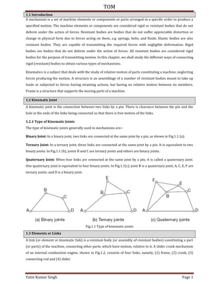
  • 1. TOM Yatin Kumar Singh Page 1 1.1 Introduction A mechanism is a set of machine elements or components or parts arranged in a specific order to produce a specified motion. The machine elements or components are considered rigid or resistant bodies that do not deform under the action of forces. Resistant bodies are bodies that do not suffer appreciable distortion or change in physical form due to forces acting on them, e.g. springs, belts, and fluids. Elastic bodies are also resistant bodies. They are capable of transmitting the required forces with negligible deformation. Rigid bodies are bodies that do not deform under the action of forces. All resistant bodies are considered rigid bodies for the purpose of transmitting motion. In this chapter, we shall study the different ways of connecting rigid (resistant) bodies to obtain various types of mechanisms. Kinematics is a subject that deals with the study of relative motion of parts constituting a machine, neglecting forces producing the motion. A structure is an assemblage of a number of resistant bodies meant to take up loads or subjected to forces having straining actions, but having no relative motion between its members. Frame is a structure that supports the moving parts of a machine. 1.2 Kinematic Joint A kinematic joint is the connection between two links by a pin. There is clearance between the pin and the hole in the ends of the links being connected so that there is free motion of the links. 1.2.1 Type of Kinematic Joints The type of kinematic joints generally used in mechanisms are:- Binary Joint: In a binary joint, two links are connected at the same joint by a pin, as shown in Fig.1.1 (a). Ternary Joint: In a ternary joint, three links are connected at the same joint by a pin. It is equivalent to two binary joints. In Fig.1.1 (b), joints B and C are ternary joints and others are binary joints. Quaternary Joint: When four links are connected at the same joint by a pin, it is called a quaternary joint. One quaternary joint is equivalent to four binary joints. In Fig.1.1(c), joint B is a quaternary joint; A, C, E, F are ternary joints; and D is a binary joint. Fig.1.1 Type of kinematic joints 1.3 Elements or Links A link (or element or kinematic link) is a resistant body (or assembly of resistant bodies) constituting a part (or parts) of the machine, connecting other parts, which have motion, relative to it. A slider crank mechanism of an internal combustion engine, shown in Fig.1.2, consists of four links, namely, (1) frame, (2) crank, (3) connecting rod and (4) slider.
  • 2. TOM Yatin Kumar Singh Page 2 Fig.1.2 Kinematic links of a slider crank mechanism 1.3.1 Classification of Links Links can be classified as binary, ternary, or quaternary depending upon the ends on which revolute or turning pairs can be placed, as shown in Fig.1.3. A binary link has two vertices, a ternary has three vertices, and a quaternary link has four vertices, and so on. Fig.1.3 Types of links There are four types of links: rigid, flexible, fluid, and floating links. Rigid Link: A rigid link does not undergo any deformation while transmitting motion. Links in general are elastic in nature. They are considered rigid if they do not undergo appreciable deformation while transmitting motion, e.g. connecting rod, crank, tappet rod, etc. Flexible Link: A flexible link is one which while transmitting motion is partly deformed in a manner not to affect the transmission of motion, e.g. belts, ropes, chains, springs, etc. Fluid Link: A fluid link is deformed by having fluid in a closed vessel and the motion is transmitted through the fluid by pressure, as in the case of a hydraulic press, hydraulic jack, and fluid brake. Floating Link: It is a link which is not connected to the frame. 1.4 Kinematic Pair The two links of a machine, when in contact with each other, are said to form a pair. A kinematic pair consists of two links that have relative motion between them. In Fig.1.2, links 1 and 2, 2 and 3, 3 and 4, and 4 and 1 constitute kinematic pairs. 1.4.1 Classification of Kinematic Pairs Kinematic pairs may be classified according to the following considerations:  Type of relative motion  Type of contact  Type of mechanical constraint.
  • 3. TOM Yatin Kumar Singh Page 3 Kinematic Pairs According to the Relative Motion Sliding Pair: It consists of two elements connected in such a manner that one is constrained to have sliding motion relative to another. For example, a rectangular bar in a rectangular hole (Fig.1.4(a)), piston and cylinder of an engine, cross-head and guides of a steam engine, ram and its guides in a shaper, tailstock on the lathe bed, etc. all constitute sliding pairs. Turning (Revolute) Pair: It consists of two elements connected in such a manner that one is constrained to turn or revolve about a fixed axis of another element. For example, a shaft with collar at both ends revolving in a circular hole (Fig.1.4 (b)) crankshaft turning in a bearing, cycle wheels revolving over their axles, etc. all constitute turning pairs. Rolling Pairs: When two elements are so connected that one is constrained to roll on another element which is fixed, forms a rolling pair. Ball and roller bearings, a wheel rolling on a flat surface (Fig.1.4(c)) are examples of rolling pairs. Screw (or Helical) Pair: When one element turns about the other element by means of threads, it forms a screw pair. The motion in this case is a combination of sliding and turning. The lead screw of a lathe with nut, bolt with a nut Fig.1.4 (d), screw with nut of a jack, etc. are some examples of screw pairs. Spherical Pair: When one element in the form of a sphere turns about the other fixed element, it forms a spherical pair. The ball and socket joint Fig.1.4 (e), pen stand, the mirror attachment of vehicles, etc. are some examples of spherical pair. Kinematic Pairs According to the Type of Contact Lower Pair: When the two elements have surface (or area) contact while in motion and the relative motion is purely turning or sliding, they are called a lower pair. All sliding pairs, turning pairs, and screw pairs form lower pairs. For example, nut turning on a screw, shaft rotating in a bearing, universal joint, all pairs of a slider crank mechanism, pantograph etc., are lower pairs. Higher Pairs: When the two elements have point or line contact while in motion and the relative motion being the combination of sliding and turning, then the pair is known as a higher pair. Belts, ropes, and chains drive, gears, cam and follower, ball and roller bearings, wheel rolling on a surface, etc., all form higher pairs. Kinematic Pairs According to the Type of Mechanical Constraint: Closed Pair: When the two elements of a pair are held together mechanically in such a manner that only the required type of relative motion occurs, they are called a closed pair. All lower pairs and some higher pairs (e.g. enclosed cam and follower) are closed pairs (Fig.1.5 (a)). Unclosed Pair: When the two elements of a pair are not held mechanically and are held in contact by the action of external forces, are called unclosed pair, e.g. cam and spring loaded follower pair (Fig.1.5 (b)).
  • 4. TOM Yatin Kumar Singh Page 4 Fig.1.4 Types of kinematic pairs according to the type of relative motion Fig.1.5 Closed and unclosed pairs 1.5 Constrained Motion The three types of constrained motion are as follows:
  • 5. TOM Yatin Kumar Singh Page 5 Completely Constrained Motion: When the motion between a pair takes place in a definite direction irrespective of the direction of force applied, then the motion is said to be a completely constrained motion. For example, a square bar in a square hole, a shaft with collars at each end in a circular hole, a piston in the cylinder of an internal combustion engine, have all completely constrained motion. Partially (or Successfully) Constrained Motion: When the constrained motion between a pair is not completed by itself but by some other means, it is said to be successfully constrained motion. For example, the motion of a shaft in a footstep bearing becomes successfully constrained motion when compressive load is applied to the shaft (Fig.1.6 (a)). Incompletely Constrained Motion: When the motion between a pair can take place in more than one direction, it is said to be incompletely constrained motion, e.g. a circular shaft in a circular hole. (Fig.1.6 (b)). Fig.1.6 Types of constrained motion 1.6 Kinematic Chain A kinematic chain may be defined as an assembly of links in which the relative motion of the links is possible and the motion of each relative to the others is definite. The last link of the kinematic chain is attached to the first link. The four-bar mechanism and the slider crank mechanism are some of the examples of a kinematic chain. The following relationship holds for a kinematic chain having lower pairs only: � = � − . � = � − . Where L = number of binary links; P = number of lower pairs; J = number of binary joints. If LHS > RHS, then chain is called Locked Chain or Redundant Chain. LHS = RHS, then chain is Constrained LHS < RHS, then chain is Unconstrained For a kinematic chain having higher pairs, each higher pair is taken equivalent to two lower pairs and an additional link. In that case, � + � = � − .
  • 6. TOM Yatin Kumar Singh Page 6 where H = number of higher pairs. 1.7 Mechanism When one of the links of a kinematic chain is fixed, the chain is called a mechanism. 1.7.1 Types of Mechanisms: The mechanisms are of the following types: Simple Mechanism: A mechanism which has four links. Compound Mechanism: A mechanism which has more than four links Complex Mechanism: It is formed by the inclusion of ternary or higher order floating link to a simple mechanism. Planar Mechanism: When all the links of the mechanism lie in the same plane. Spatial Mechanism: When the links of the mechanism lie in different planes. 1.7.2 Equivalent Mechanisms Turning pairs of plane mechanisms may be replaced by other types of pairs such as sliding pairs or cam pairs. The new mechanism thus obtained having the same number of degrees of freedom as the original mechanism is called the equivalent mechanism. The equivalent mechanism will have same degrees of freedom and shall be kinematically similar. The following rules may be used to obtain the equivalent mechanism: A sliding pair is equivalent to a turning pair, as shown in Fig.1.13 (a). A spring can be replaced by two binary links, as shown in Fig.1.13 (b). A cam pair can be replaced by one binary link together with two turning pairs at each end, as shown in Fig.1.13(c).
  • 7. TOM Yatin Kumar Singh Page 7 Fig.1.13 Equivalent mechanisms 1.8 Mechanism and Machines A machine is a device that transforms energy available in one form to another to do certain type of desired useful work. The parts of the machine move relative to one another. Its links may transmit both power and motion. On the other hand, a mechanism is a combination of rigid or restraining bodies, which are so shaped and connected that they move upon each other with definite relative motion. A mechanism is obtained when one of the links of the kinematic chain is fixed. A machine is a combination of two or more mechanisms arranged in such a way so as to obtain the required motion and transfer the energy to some desired point by the application of energy at some other convenient point. A machine is not able to move itself and must get the motive power from some source. Some examples of mechanisms are: slider crank, typewriter, clocks, watches, spring toys, etc. Steam engine, internal combustion engine, lathe, milling machine, drilling machine, etc. are some examples of machines. 1.8.1 Classification of Machines The machines may be classified as the following: Simple Machine: In a simple machine, there is one point of application for the effort and one point for the load to be lifted. Some examples of simple machines are lever, screw jack, inclined plane, bicycle, etc. Compound Machine: In a compound machine, there are more than one point of application for the effort and the load. It may be thought of as a combination of many simple machines. Some examples of compound machines are lathe machine, grinding machine, milling machine, printing machine, etc. 1.9 Degrees of Freedom An unconstrained rigid body moving in space can have three translations and three rotational motions (i.e. six motions) about the three mutually perpendicular axes. Degrees of freedom of a kinematic pair is defined as the number of independent relative motions, both translational and rotational, a kinematic pair can have. � = − The degrees of freedom of some of the systems are as follows:  A rigid body has 6 degrees of freedom.  A rectangular bar sliding in a rectangular hole has one degree of freedom as the motion can be expressed by the linear displacement only.  The position of the crank of a slider crank mechanism can be expressed by the angle turned through and thus has one degree of freedom.
  • 8. TOM Yatin Kumar Singh Page 8  A circular shaft rotating in a hole and also translating parallel to its axis has two degrees of freedom, i.e. angle turned through and displacement.  A ball and a socket joint has three degrees of freedom. 1.9.1 Degrees of Freedom of Planar Mechanisms Mobility of a mechanism: The mobility of a mechanism is defined as the number of degrees of freedom it possesses. An equivalent definition of mobility is the minimum number of independent parameters required to specify the location of every link within a mechanism. Kutzbach Criterion: The Kutzbach criterion for determining the number of degrees of freedom of a planar mechanism is: � = � − − − � . where F = degrees of freedom n = total number of links in a mechanism out of which one is a fixed link. n − 1 = number of movable links p = number of simple joints or lower pairs having one degree of freedom h = number of higher pairs having two degrees of freedom and so on. When two links are joined by a hinge, two degrees of freedom are lost. Hence for each joint two degrees of freedom are lost. Therefore, for p number of joints the number of degrees of freedom lost are 2p. When a kinematic chain is made up of different type of links, then the number of lower pairs p is computed as follows: = � + � + � + ⋯ . where n2 = number of binary links n3 = number of ternary links, and so on. To determine the degrees of freedom of a mechanism, the presence of a redundant link or redundant pair may also be considered. (i) A mechanism may have one or more links which do not introduce any extra constraint. Such links are called redundant links (nr) and should not be taken into account. Similarly redundant joints (pr) should also not be taken into account. In Fig.1.14(a), links 3 and 4 are parallel and are termed as redundant links, as none of them produces extra constraint. By removing one of the two links, the motion remains the same. So one of the two links is considered for calculating the degrees of freedom. The corresponding kinematic pairs either between links 4 and 2, and 4 and 5; or 3 and 2, and 3 and 5 are considered as redundant pair. Therefore, either of the two links and the corresponding kinematic pair should be considered while calculating the degrees of freedom.
  • 9. TOM Yatin Kumar Singh Page 9 Fig.1.14 In Fig.1.14(b), links AB and CD are identical and each leads to same constraint. (ii) Sometimes one or more links of a mechanism may have redundant degrees of freedom. If a link can be moved without causing any movement in the rest of the mechanism then the link is said to have redundant degree of freedom (Fr). Fig.1.15 In Fig.1.15 (a), the link 3 can slide without causing any movement to the mechanism. Thus link 3 represents one redundant degree of freedom. In Fig.1.15 (b), roller can rotate without causing any movement in the rest of the mechanism. Thus Eq. (1) can be modified as: � = � − � − − − − � − � . 1.9.2 Planar Mechanisms with Lower Pairs Only For linkages with lower pairs only, h = 0, and � = � − − . A joint connecting k links at a single joint must be counted as k − 1 joints. Only four types of joints are commonly found in planar mechanisms. These are the revolute, the prismatic, the rolling contact joints (each having one degree of freedom), and the cam or gear joint (each having two degrees of freedom). These joints are depicted in Fig.1.16. The following definitions apply to the actual degrees of freedom of a device. F 1: the device is a mechanism with F degrees of freedom. F = 0: the device is a Statically Determinate Structure. F < − 1: the device is a Statically Indeterminate Structure.
  • 10. TOM Yatin Kumar Singh Page 10 Fig.1.16 Common types of joints found in planar mechanisms The degrees of freedom of some of the planar mechanisms have been listed in Table 1.1. Table 1.1 Degrees of Freedom of Planar Mechanisms Gruebler’s Criterion: For a constrained motion, F = 1, so that = n − − p − h Or + � − � + = . Eq. . represents the Gruebler s criterion. If h = 0, then = � − . Therefore, a planar mechanism with F = 1 and having only lower pairs, cannot have odd number of links.
  • 11. TOM Yatin Kumar Singh Page 11 Eq. (1.8) is similar to Eq. (1.1 b) with p = J and n = L. As p and n are to be whole numbers, the relation can be satisfied only if n is even. For possible linkages made of binary links only, n = 4, p = 4 No excess turning pair n = 6, p = 7 One excess turning pair n = 8, p = 10 Two excess turning pair and so on. Thus, we find that the number of excess turning pairs increase as the number of links increase. To get the required number of turning pairs from the same number of binary links is not possible. Therefore, the additional pairs or joints can be obtained only from the links having more than two joining points, i.e., ternary or quaternary links, etc. 1.10 Four-Bar Chain A four-bar chain has been shown in Fig.1.17. It consists of four binary links. Link AD is fixed (called frame), AB is the crank (or driver link), BC is the coupler (or connecting rod), and CD the lever (or rocker or follower link . θ is the input angle and ϕ the angle of transmission. The coupler BC may be a ternary link. The number of degrees of freedom of the four-bar chain is one. A link that makes complete revolutions is the crank, the link opposite to the fixed link is the coupler, and the fourth link a lever or rocker, if it oscillates or another crank, if it rotates. The four-bar mechanism with all its pairs as turning pairs is called the Quadric Cycle Chain. When one of these turning pairs is replaced by a slider pair, the chain becomes Single Slider Chain. When two turning pairs are replaced by slider pairs, it is called a Double Slider Chain or a Crossed Double Slider Chain, depending on whether the two slider pairs are adjacent or crossed. Fig.1.17 Four-bar chain 1.11 Grashof’s Law This law states that for a four-bar mechanism the sum of the lengths of the largest and the shortest links should be less than or equal to the sum of the lengths of the other links, that is, � + ≤ + . where l, s = lengths of the longest and the shortest links, respectively. p, q = lengths of the other two links.
  • 12. TOM Yatin Kumar Singh Page 12 Consider the four-bar chain shown in Fig.1.25. Let the length of fixed link O2O4 = l1, crank O2A = l2, coupler AB = l3, and lever BO4 = l4. The following types of mechanisms are obtained by adjusting the lengths of various links: Fig.1.25 Four-bar chain 1.11.1 Crank–Crank (or Double Crank) Mechanism When the shortest link is fixed and l + s ≤ p + q , crank-crank or double crank mechanism is obtained, as shown in Fig.1.26. Links O2A or O4B may be the inputs links or cranks. They are able to make complete rotations about points O2 and O4 respectively. Shortest link O2O4 = l1 is fixed. A four-bar mechanism behaves as a crank-crank when the following conditions exist: l1 < l2 or l3 or l4 and l1 < (l3 + l4 − l2) and l1 < (|l3 − l4 | + l2) where || stands for absolute value. Fig.1.26 Crank–crank mechanism 1.11.2 Crank–Rocker (or Lever) Mechanism )f any of the adjacent links of shortest link l i.e., l2 or l4 is fixed then l1 can have full revolution and the link l3 opposite to it oscillates. In Fig.1.27 (a , l2 is fixed, l1 is the crank to rotate about O2 and l3 oscillates, whereas in Fig.1.27 (b), l4 is fixed, l1 is the crank to rotate about O4 and l3 oscillates. Again l + s p + q applies.
  • 13. TOM Yatin Kumar Singh Page 13 A four-bar mechanism behaves as a crank-rocker, when the following conditions exist: l2 < l1 or l3 or l4 and l1 < (l3 + l4 − l2) and l1 > (|l3 − l4| + l2) Fig.1.27 Crank–rocker mechanism 1.11.3 Rocker–Rocker (or Double Rocker) Mechanism If the link l3 opposite to the shortest link l1 is fixed and shortest link l1 is made the coupler, the other two links l and l would oscillate, as shown in Fig.1.28 (a . When l + s ≤ p + q , the linkage is known as a class- I four-bar linkage. A four-bar mechanism behaves as a double rocker mechanism when the following condition is met: l3 < l1 or l2 or l4 Fig.1.28 Rocker–rocker mechanism 1.11.4 Class-II Four-Bar Linkage When (l + s) > (p + q), the linkage is known as a class-II four-bar linkage. In such a mechanism, fixing of any of the links always results in rocker-rocker mechanism, as shown in Fig.1.28(b). 1.12 Inversion of Mechanisms A kinematic chain becomes a mechanism when one of its links is fixed. Therefore, as many numbers of mechanisms can be obtained as many are the links in the kinematic chain. This method of obtaining different mechanisms by fixing different links of a kinematic chain is called inversion of the mechanism. The relative
  • 14. TOM Yatin Kumar Singh Page 14 motion between the various links is not altered as a result of inversion, but their absolute motion with respect to the fixed link may alter drastically. 1.12.1 Inversions of a Four-Bar Chain Some of the important inversions of a four-bar chain are:  Beam Engine  Coupled Wheel of Locomotive  Watt s Indicator Mechanism  Slider-Crank Chain. 1. Beam Engine: The beam engine mechanism is shown in Fig.1.31. It consists of four links. When the crank AB rotates about the fixed centre A, the lever oscillates about a fixed centre D. The end E of the lever CDE is connected to a piston rod which moves the piston up and down in the cylinder. This is also called crank and lever mechanism. Fig.1.31 Beam engine 2. Coupled Wheel of a Locomotive: In this mechanism, as shown in Fig.1.32, the links AB and CD are of equal lengths and act as cranks. These cranks are connected to the respective wheels. The link BC acts as the connecting rod. The link AD is fixed to maintain constant distance between the wheels. This mechanism is used to transmit rotary motion from one wheel to the other. This is also called the double crank mechanism. Fig.1.32 Coupled wheel of a locomotive 3. Watt’s Indicator Mechanism: This mechanism is shown in Fig.1.33. It consists of four links: a fixed link at A, link AC, link CE, and link BFD. The links CE and BFD act as levers. The displacement of link BFD is directly proportional to the pressure in the indicator cylinder. The point E on link CE traces out an approximate straight line. It is also called double lever mechanism.
  • 15. TOM Yatin Kumar Singh Page 15 Fig.1. Watt’s indicator mechanism 4. Single Slider-Crank Chain: The single slider-crank chain shown in Fig.1.34 consists of three turning pairs and one sliding pair. Link 1 corresponds to the frame of the mechanism, which is fixed. Link 2 is the crank and link 3 the connecting rod. The link 4 is the slider. It is used to convert rotary motion into reciprocating motion and vice-versa. Its important applications are in steam engines, internal combustion engines, reciprocating compressors, etc. If the straight line path of the slider is offset from the fixed point of the crank then it is called offset slider-crank chain. The offset is called the eccentricity. Fig.1.34 Single-slider crank mechanism 1.12.2 Inversions of a Single-Slider Crank Chain The inversions of a single slider crank chain are as follows:  Pendulum Pump  Oscillating Cylinder Engine  Rotary Internal Combustion Engine  Crank And Slotted Lever Quick-Return Motion Mechanism  Whitworth Quick-Return Motion Mechanism. 1. Pendulum Pump: This inversion mechanism is obtained by fixing the link 4, i.e., the sliding pair, as shown in Fig.1.35. When the link 2 (i.e., the crank) rotates, the link 3 (i.e., connecting rod) oscillates about a pin pivoted to fixed link 4 at C and the piston attached to the piston rod (link 1) reciprocates in the cylinder. It is used to supply feed water to a boiler.
  • 16. TOM Yatin Kumar Singh Page 16 Fig.1.35 Pendulum pump 2. Oscillating Cylinder Engine: In this mechanism, as shown in Fig.1.36, link 3 is fixed. When the crank (link 2) rotates, the piston attached to piston rod (link 1) reciprocates and the cylinder (link 4) oscillates about a pin pivoted to the fixed link at A. Fig.1.36 Oscillating cylinder engine 3. Rotary Internal Combustion Engine (Gnome Engine): It consists of several cylinders in one plane and all revolve about fixed centre O, as shown in Fig.1.37. The crank (link 2) is fixed. When the connecting rod (link 4) rotates, the piston (link 3) reciprocates inside the cylinder forming link 1. Fig.1.37 Rotary internal combustion engine 4. Crank and Slotted Lever Quick-Return Motion Mechanism: In this mechanism, as shown in Fig.1.38, the link AC (link 3) corresponding to the connecting rod is fixed. The driving crank CB (link 2) revolves about centre C. A slider (link 1) attached to the crank pin at B slides along the slotted lever AP (link 4) and makes the slotted lever oscillate about the pivoted point A. A short link PQ transmits the motion from AP to the arm
  • 17. TOM Yatin Kumar Singh Page 17 which reciprocates with the tool along the line of stroke. The line of stroke is perpendicular to AC produced. This mechanism is mostly used in shaping machines, slotting machine, and rotary internal combustion engines. � � = . = � / . Fig.1.38 Crank and slotted lever quick-return motion mechanism 5. Whitworth Quick-Return Motion Mechanism: In this mechanism, as shown in Fig.1.39, link CD (link 2) is fixed. The driving crank CA (link 3) rotates about C. The slider (link 4) attached to the crank pin at A slides along the slotted lever PA (link 1), which oscillates about pivot D. Fig.1.39 Whitworth quick-return motion mechanism The connecting rod PQ carries the ram at Q with cutting tool. The ram reciprocates along the line of stroke. It is used in shaping and slotting machines. � � = .
  • 18. TOM Yatin Kumar Singh Page 18 = � . 6. Toggle Mechanism: This mechanism has many applications where it is necessary to overcome a large resistance with a small driving force. Fig.1.40 shows the toggle mechanism; links 4 and 5 are of equal length. As the angles decrease and links and approach being collinear, the force F required to overcome a given resistance P decreases as: � = � . )f approaches zero, for a given F, P approaches infinity. A stone crusher utilizes this mechanism to overcome a large resistance with a small force. It can be used in numerous toggle clamping devices, for holding work pieces. Fig.1.40 Toggle mechanism The summary of single slider crank chain and its inversions is given in Table 1.2. Table 1.2 Summary of Single Slider Crank Chain And Its Inversions 1.13 Double Slider-Crank Chain A kinematic chain consisting of two turning pairs and two sliding pairs is called double slider–crank chain, as shown in Fig.1.41. Links 3 and 4 reciprocate, link 2 rotates and link 1 is fixed. Two pairs of the same kind are adjacent.
  • 19. TOM Yatin Kumar Singh Page 19 Fig.1.41 Double slider–crank chain 1.13.1 Inversions of Double Slider–Crank Chain The inversions of double slider-crank chain are as follows:  Donkey Pump  Oldham s Coupling  Elliptical Trammel  Scotch Yoke. 1. Donkey Pump: Figure 1.42 shows a donkey pump, in which link 2 (crank) rotates about point A. One end of the crank is connected to the piston, through the piston rod, which reciprocates vertically in the pump cylinder. This cylinder together with the body of the pump represents the fixed link 1. The other end of the crank is connected to the slider (link 3) which reciprocates horizontally in the cylinder. Fig.1.42 Donkey pump
  • 20. TOM Yatin Kumar Singh Page 20 2. Oldham’s Coupling: The Oldham s coupling shown in Fig. . , is used to connect two parallel shafts, the distance between whose axes is small and variable. The shafts connected by the coupling rotate at the same speed. The shafts have flanges at the ends, in which slots are cut. These form links 1 and 3. An intermediate piece circular in shape and having tongues at right angles on opposite sides, is fitted between the flanges of the two shafts in such a way that the tongues of the intermediate piece get fitted in the slots of the flanges. The intermediate piece forms link 4, which slides or reciprocates in links 1 and 3. The link 2 is fixed. Fig.1. Oldham’s coupling = � × . 3. Elliptical Trammel: It is a device to draw ellipses. Fig.1.44 shows an elliptical trammel in which two grooves are cut at right angles in a plate that is fixed. The plate forms the fixed link 4. Two sliding blocks are fitted into the grooves. The slides form two sliding links 1 and 3. The link joining slides form the link 2. Any point on link 2 or on its extension traces out an ellipse on the fixed plate, when relative motion occurs. = � = � Fig.1.44 Elliptical trammel = � = � Squaring and adding, we get + = .
  • 21. TOM Yatin Kumar Singh Page 21 which is the equation of an ellipse. 4. Scotch Yoke: This mechanism gives simple harmonic motion. Its early application was on steam pumps, but it is now used as a mechanism on a test machine to produce vibrations. It is also used as a sine-cosine generator for computing elements. Fig.1.45 shows a sketch of scotch yoke mechanism. Fig.1.45 Scotch yoke = − � = − � . � = = � � . = = � � .
  • 22. TOM Yatin Kumar Singh Page 22 Example 1.1: A chain with three links is shown in Fig.1.7. Prove that the chain is locked. Fig.1.7 Three-bar chain Solution: Number of binary joints, J = 3; Number of binary links, L = 3; Number of lower pairs, P = 3 L = P − = × − = ∴ LHS > RHS Also � = ( ) � − = ( ) × − = ∴ LHS > RHS Therefore, it is a locked chain. Example 1.2 A four-bar chain is shown in Fig.1.8. Prove that it is a constrained chain. Fig.1.8 Four-bar chain Solution: Number of binary joints, J = 4; Number of binary links, L = 4; Number of lower pairs, P = 4 Now L = P − = × − = ∴ LHS = RHS Also = ( ) × − = ∴ LHS = RHS Therefore, it is a constrained chain. Example 1.3 A five-bar chain is shown in Fig.1.9. Prove that it is an unconstrained chain.
  • 23. TOM Yatin Kumar Singh Page 23 Fig.1.9 Five-bar chain Solution: Number of binary joints, J = 5; Number of binary links, L = 5; Number of lower pairs, P = 5 Now L = P − = × − = ∴ LHS < RHS Also = ( ) × − = . ∴ LHS < RHS Therefore, it is an un-constrained chain. Example 1.4 Show that the chain shown in Fig.1.10 is an unconstrained kinematic chain. Fig.1.10 Six-bar chain Solution: Number of binary joints, J = 7 (A = 1, B = 2, C = 2, D = 1, E = 1) Number of binary links, L = 6 Number of lower pairs, P = − , − , − , − , − , − , − , − , − Now L = P − = × − = ∴ LHS < RHS Also = ( ) × − = ∴ LHS < RHS Therefore, it is an un-constrained chain. Example 1.5 Show that the chain shown in Fig.1.11 is not a kinematic chain.
  • 24. TOM Yatin Kumar Singh Page 24 Fig.1.11 Nine-bar chain Solution: Number of binary joints, J = 13 (A = 2, B = 4, C = 2, D = 1, E = 2, F = 2) Number of binary links, L = 9 Number of lower pairs, P = 13 (D = 1, A, C, E, F = 2 each, B = 4) Now L = P − = × − = LHS < RHS Also = ( ) × − = . LHS > RHS Therefore, it is not a kinematic chain. It is a locked chain or a frame. Example 1.6 Determine the type of chain in Fig.1.12 (a)–(e). Fig.1.12 Different types of chains Solution: (a) (i) L = P − ii J = L/ − L = 3, P = 3, J = 3 LHS = 3 LHS = 3 R(S = × − = R(S = × / − = . LHS > RHS LHS > RHS It is a locked chain and not a kinematic chain. (b) L = 4, P = 4, J = 4 LHS = 4 LHS = 4
  • 25. TOM Yatin Kumar Singh Page 25 R(S = × − = R(S = × / − = LHS = RHS LHS = RHS It is a constrained kinematic chain. (c) L = 5, P = 5, J = 5 LHS = 5 LHS = 5 R(S = × − = R(S = × / − = . LHS < RHS LHS < RHS It is an unconstrained chain and not a kinematic chain. (d) L = 6, P = 5, J = 7 LHS = 6 LHS = 7 RHS = 2 × − = R(S = × / − = LHS = RHS LHS = RHS It is a constrained kinematic chain. (e) L = 4, P = 4, J = 4 LHS = 4 LHS = 4 R(S = × − = R(S = × / − = LHS = RHS LHS = RHS It is a constrained kinematic chain. Example 1.7 Calculate the number of degrees of freedom of the linkages shown in Fig.1.18 (a) and (b). Fig.1.18 Four- and five-bar chains Solution: (a) Number of binary links, n = 4 Number of lower pairs, p = 4 Degrees of freedom, F = n − − p = − − × = (b) Number of binary links, n = 5 Number of lower pairs, p = 5 Degrees of freedom, F = n − − p = − − × = Example 1.8 Calculate the number of degrees of freedom of the linkages shown in Fig.1.19 (a) to (c).
  • 26. TOM Yatin Kumar Singh Page 26 Fig.1.19 Various types of linkages Solution: In Fig.1.19 (a), links 3 and 4 are parallel and are termed as redundant links, as one of them produces extra constraint. By removing one of these two links, the motion remains same so one of the two links is considered for calculating the degrees of freedom. Number of binary links, n = 4 Number of lower pairs, p = 4 Degrees of freedom, F = n − − p = − − × = − = 2. Number of binary links, n = 8 Number of simple joints: Binary joints at C and F = 2 Ternary joints at A, B, D and E = 4 P = 2 + 2 × 4 = 10 Degrees of freedom, F = n − − p = − − × = − = 3. Number of binary links, n = 14 Number of lower pairs, p = 18 Number of higher pairs, h = 1 (Slider can rotate and slide) Degrees of freedom, F = n − − p – h = − − × – 1 = − − = Example 1.9 Determine the number of degrees of freedom of the mechanism shown in Fig.1.20 (a) to (f).
  • 27. TOM Yatin Kumar Singh Page 27 Fig.1.20 Various types of mechanisms Solution: 1. Number of binary links, n2 = 3 Number of ternary links, n3 = 2 Total number of links, n = n2 + n3 = 3 + 2 = 5 2p = 2n2 + 3n3 = 2 × 3 + 3 × 2 = 12 Degrees of freedom, F = n − − p = − − = − = 0 It is a structure. 2. Number of binary links, n2 = 5 Number of ternary links, n3 = 2 Total number of links, n = n2 + n3 = 5 + 2 = 7 2p = 2n2 + 3n3 = 2 × 5 + 3 × 2 = 16 Degrees of freedom, F = n − − p = − − = − = 3. The roller 3 carried at the end of the output link 2 can be rotated without causing any motion in the rest of the mechanism. Thus roller 3 is a link with redundant degree of freedom. The roller can thus be considered welded to the output link. Hence, there are three binary links 1, 2 and 4 together with two turning pairs 12, 14 and one higher pair 34. Thus n = 3, p = 2, h = 1 Degrees of freedom, F = n − − p − h = − − × − = − − = 4. Number of binary links, n2 = 4 Number of ternary links, n3 = 2 Total number of links, n = n2 + n3 = 4 + 2 = 6 2p = 2n2 + 3n3 = 2 × 4 + 3 × 2 = 14 F = n − − p = − − = − = 5. Number of binary links, n2 = 5 Number of ternary links, n3 = 2 Number of quaternary links, n4 = 1 Total number of links, n = n2 + n3 + n4 = 5 + 2 + 1 = 8
  • 28. TOM Yatin Kumar Singh Page 28 2p = 2n2 + 3n3 + 4n4 = 2 × 5 + 3 × 2 + 4 × 1 = 20 F = n − − p = − − = − = 6. Number of binary links, n2 = 5 Number of ternary links, n3 = 2 Total number of links, n = n2 + n3 = 5 + 2 = 7 2p = 2n2 + 3n3 = 2 × 5 + 3 × 2 = 16 F = n − − p = − − = − = Example 1.10 Determine the number of degrees of freedom of the mechanism shown in Fig.1.21(a) to (f). Fig.1.21 Various types of mechanisms Solution: 1. n2 = 3, n3 = 2, n = 5 2p = 2 × 3 + 3 × 2 = 12 F = − − = 2. n2 = 4, n3 = 2, n = 6 2p = 2 × 4 + 3 × 2 = 14 F = − − = 3. n2 = 5, n3 = 2, n4 = 1, n = 8 2p = 2 × 5 + 3 × 2 + 4 + 1 = 20 F = − − = 4. n2 = 4, n3 = 2, n = 6 2p = 2 × 4 + 3 × 2 = 14 F = − − = 5. n2 = 5, n3 = 2, n = 5 + 2 = 7 2p = 2n2 + 3n3 = 2 × 5 + 3 × 2 = 16 F = n − − p = − − = − = 6. The solution has been given in Example 1.9(c). Example 1.11 Determine the number of degrees of freedom of the mechanism shown in Fig.1.20 (a)–(h).
  • 29. TOM Yatin Kumar Singh Page 29 Fig.1.22 Various types of mechanisms Solution: 1. Number of binary links, n2 = 7 Number of ternary links, n3 = 2 Number of quaternary links, n4 = 1 Total number of links, n = n2 + n3 + n4 = 7 + 2 + 1 = 10 2p = 2n2 + 3n3 + 4n4 = 2 × 7 + 3 × 2 + 4 × 1 = 24 F = n − − p = − − = − = 2. n = 7, p = 7, h = 1 F = n − − p − h = − − × − = − − = Example 1.12 Find the equivalent mechanisms with turning pairs for the mechanisms shown in Figs.1.23(a) to (d). Solution: A spring can be replaced by two binary links. Therefore, the equivalent mechanism is as shown in Fig.1.23a (ii). 2. A cam pair can be replaced by one binary link with two turning pairs at each end. Therefore, the equivalent mechanism is shown in Fig.1.23b(ii). The centres of curvature at the point of contact E lie at B and C, respectively.
  • 30. TOM Yatin Kumar Singh Page 30 3. The equivalent mechanism is shown in Fig.1.23c (ii) as explained in (b) above. 4. A spring is equivalent to two binary links connected by a turning pair. A cam follower is equivalent to one binary link with turning pairs at each end. The equivalent chain with turning pairs is shown in Fig.1.23d (ii). Example 1.13 Calculate the degrees of freedom of the mechanisms shown in Fig.1.24(a–e). Fig.1.24 Various types of mechanisms Solution :
  • 31. TOM Yatin Kumar Singh Page 31 1. n2 = 4, n3 = 2, n = 4 + 2 = 6 2p = 2n2 + 3n3 = 2 × 4 + 3 × 2 = 14 F = n − − p − h = − − − = − = 2. n = 13 Binary pairs: A, B, C, D, E, F, G, H, K, L, M, N, P, two at Q and one slider. P = 16 F = n − − p = − − × = − = 3. n2 = 5, n3 = 3, n = 5 + 3 = 8 2p = 2 × 5 + 3 × 3 = 19 F = n − − p = − − = − = 4. n = 5, p = 5, h = 1 (cam pair) F = n − − p − h = − − × − = − − = 5. n = 12, p = 15, h = 1 F = n − − p − h = − − × − = − − = Example 1.14 Identify the nature of each mechanism shown in Fig.1.29 (a) to (d). Solution: 1. l1 = 5 cm, l2 = 7 cm, l3 = 10 cm, l4 = 9 cm; l = 10 cm, s = 5 cm, p + q = 7 + 9 = 16 cm l + s = 10 + 5 = 15 cm (l + s = 15 cm) < (p + q = 16 cm) (ence Grashof s law is satisfied. l1 < l2 < l3 < l4, i.e. 5 < 7 < 10 < 9, hence valid. l3 + l4 − l2 = + − = cm ∴ (l1 = 5 cm) < 12 cm. Hence, valid. |l3 − l4| + l2 = | − | + = cm (l1 = 5 cm) < 8 cm. Hence, valid. The shortest link l1 is fixed. Hence, it is a double crank (or drag link) mechanism. 2. l1 = 10 cm, l2 = 6 cm, l3 = 11 cm, l4 = 9 cm; l = 11 cm, s = 6 cm, l + s = 11 + 6 = 17 cm, p + q = 10 + 9 = 19 cm
  • 32. TOM Yatin Kumar Singh Page 32 (l + s = 17 cm) < (p + q = 19 cm) (ence Grashof s law is satisfied. l2 < l1 or l3 or l4. Hence, valid. l3 + l4 − l2 = + − = cm (l1 = 10 cm) < (l3 + l4 − l2 = 14 cm). Hence, valid. |l3 − l4| + l2 = |11 − | + = cm (l1 = 10 cm) > (l3 − l4) + l2 = 8 cm Hence, valid. The link l1 adjacent to the shortest link l2 is fixed. Therefore, it is a crank-rocker mechanism. 3. ll = 11 cm, l2 = 6 cm, l3 = 12 cm, l4 = 10 cm; l = 12 cm, s = 6 cm, l + s = 12 + 6 = 18 cm, p + q = 11 + 10 = 21 cm (l + s = 18 cm) < (p + q = 21 cm) (ence, Grashof s law is satisfied. l2 < l1 or l3 or l4. Hence, valid. l3 + l4 − l2 = + − = cm ∴ l1 < (l3 + l4 − l2). Hence, valid. |l3 − l4| + l2 = | − | + = cm ∴ l1 > (|l3 − l4| + l2). Hence, valid. The link l1 adjacent to the shortest link l2 is fixed. Therefore, it is a crank-rocker mechanism. 4. l1 = 9 cm, l2 = 7 cm, l3 = 5 cm, l4 = 8 cm; l = 9 cm, s = 5 cm, l + s = 9 + 5 = 14 cm, p + q = 7 + 8 = 15 cm (l + s = 14 cm) < (p + q = 15 cm) (ence, Grashof s law is satisfied. l3 < l1 < l2 < l4. Hence, valid. The link l1 opposite to the shortest link l3 (coupler) is fixed. Therefore, it is a rocker-rocker mechanism. Example 1.15 Identify the nature of the mechanisms shown in Fig.1.30(a) to (d).
  • 33. TOM Yatin Kumar Singh Page 33 Fig.1.30 Four-bar mechanisms Solution: 1. l1 = 100 mm, l2 = 400 mm, l3 = 700 mm, l4 = 800 mm; l = 800 mm, s = 100 mm, l + s = 800 + 100 = 900 mm, p + q = 400 + 700 = 1100 mm (l + s = 900 mm) < (p + q = 1100 mm) (ence, Grashof s law is satisfied. l1 < l2 < l3 < l4, i.e. 100 < 400 < 700 < 800. Hence, valid. l3 + l4 − l2 = + − = mm l1 < (l3 + l4 − l2). Hence, valid. |l3 − l4| + l2 = | − | + = mm |l1 < |l3 − l4| + l2 The shortest link is fixed. Therefore, it is a crank-crank mechanism. 2. l1 = 700 mm, l2 = 800 mm, l3 = 100 mm, l4 = 400 mm; l = 800 mm, s = 100 mm, l + s = 800 + 100 = 900 mm, p + q = 700 + 400 = 1100 mm (l + s = 900 mm) < (p + q = 1100 mm) (ence, Grashof s law is valid. l3 < l1 < l2 < l4. Hence, valid. The link l1 opposite to the shortest link l3 (coupler) is fixed. Therefore, it is a rocker-rocker mechanism. 3. l1 = 800 mm, l2 = 100 mm, l3 = 400 mm, l4 = 700 mm; l = 800 mm, s = 100 mm, l + s = 800 + 100 = 900 mm, p + q = 400 + 700 = 1100 mm (l + s = 900 mm) < (p + q = 1100 mm) (ence, Grashof s law is satisfied. l2 < l1 < l3 < l4. Hence, valid. l3 + l4 − l2 = + − = mm l1 < (l3 + l4 − l2). Hence, valid. |l3 − l4| + l2 = | − | + = mm l1 > |l3 − l4| + l2. Hence, valid. The link l1 adjacent to the shortest link l2 is fixed. Therefore, it is a crank-rocker mechanism. 4. l1 = 250 mm, l2 = 300 mm, l3 = 350 mm, l4 = 450 mm; l = 450 mm, s = 250 mm, l + s = 450 + 250 = 700 mm, p + q = 300 + 350 = 650 mm (l + s) > (p + q) Therefore, it is a rocker-rocker mechanism of class-II. Example 1.16 In a crank and slotted lever quick-return mechanism shown in Fig.1.46, the distance between the fixed centres is 300 mm and the length of the driving crank is 150 mm. Find the inclination of the slotted lever with the vertical in the extreme position and the ratio of time of cutting stroke to return stroke. Solution: Given: AC = 300 mm, B1C = 150 mm cos ( ) = = = .
  • 34. TOM Yatin Kumar Singh Page 34 Fig.1.46 Crank and slotted lever mechanism �im� o� c���in� s�rok� �im� o� r���rn s�rok� = = ° ° = �nclina�ion o� slo���d l���r �i�� ��� ��r�ical = ° − = ° − ° = ° Example 1.17 In a Whitworth quick return motion mechanism, as shown in Fig.1.47, the distance between the fixed centres is 80 mm and the length of the driving crank is 100 mm. The length of the slotted lever is 180 mm and the length of the connecting rod is 150 mm. Calculate the ratio of the time of cutting to return strokes. Solution: Given: CD = 80 mm, CA = 100 mm, PA = 180 mm, PQ = 150 mm cos ( ) = = = . �im� o� c���in� s�rok� �im� o� r���rn s�rok� = ° − = . ° . ° = . Fig.1.47 Whitworth mechanism
  • 35. TOM Yatin Kumar Singh Page 35 Example 1.18 The distance between two parallel shafts connected by Oldham s coupling is mm. The driving shaft revolves at 240 rpm. Determine the maximum speed of sliding of the tongue of the intermediate piece along its groove. Solution : d = 25 mm, n = 240 rpm � = � × = . rad/s Maximum velocity of sliding = ω × d = . × . = . m/s Example 1.19 In a crank and slotted lever mechanism, the length of crank is 560 mm and the ratio of time of working stroke to return stroke is 2.8. Determine (a) distance between the fixed centres, and (b) the length of the slotted lever, if length of stroke is 250 mm. Solution: Given: AB = 560 mm, stroke = 250 mm, ratio of times = 2.8 The mechanism is shown in Fig.1.48. �im� o� �orkin� s�rok� �im� o� r���rn s�rok� = ° − = . cos ( ) = = cos . ° = . mm ��n��� o� s�rok� = D D = D D = sin ( ° − ) = sin . ° Length of slotted lever. CD1 = 169.9 mm. Fig. 1.48 Crank and slotted lever mechanism Example 1.20 The configuration of a drag link mechanism is shown in Fig.1.49. Determine the time ratio and the length of stroke. The crank O2A rotates clockwise.
  • 36. TOM Yatin Kumar Singh Page 36 Fig.1.49 Drag link mechanism Solution: The drag link mechanism has been drawn as O2ABO4 to scale of 1 cm = 10 mm. The extreme positions of B are B1 and B2. The length of stroke is 2 × O4B = B1B2 = 2 × 60 = 120 mm. When B is at B1, then A is at A1 and when B is at B2, then A is at A2. By measurement, we have = ° and = ° �a�io o� �im�s = = = . Example 1.21 The distance between the axes of parallel shafts connected by Oldham s coupling is mm. The speed of rotation of the shafts is 320 rpm. Determine the maximum velocity of sliding of each tongue in its slot. Solution: cos ( / = / = / , = . ° Time of cutting stroke / Time of return stroke = ° − / = 263.6/96.4 = 2.735 Example 1.22 In crank and slotted lever quick return mechanism, the distance between the fixed centres is 150 mm and the driving crank is 100 mm long. Find the ratio of the time taken during the cutting and return strokes. Solution: d = mm, ω = π × / = . rad/s Maximum velocity of sliding = ωd = . × . = . m/s Example 1.23 Design a quick return mechanism of the type shown in Fig.1.50. The working stroke is 200 mm and the ratio of the time of working stroke to return stroke is 2:1. The driving crank is 50 mm long.
  • 37. TOM Yatin Kumar Singh Page 37 Fig.1.50 Quick-return mechanism Solution: ° − / = , = ° cos / = OB/OA OA = 50/cos 60° = 100 mm Working stroke = C1C2 = 2C1C 200 = 2AC1 sin 30° AC1 = 200 mm Length of lever, AC = 200 mm Example 1.24 Design a Whitworth quick return motion mechanism shown in Fig.1.51 to have the following particulars: Return stroke = 200 mm; Time ratio of working to return stroke = 2; Length of driving crank = 50 mm. Fig.1.51 Whitworth mechanism Solution :
  • 38. TOM Yatin Kumar Singh Page 38 ° − )/ = 2 = 120° OA = 50/cos 60° = 100 mm Return stroke = 2 × OC OC = 200/2 = 100 mm CD > OC Example 1.25 In a Whitworth quick return motion mechanism, as shown in Fig.1.52, the distance between the fixed centres is 60 mm and the length of the driving crank is 80 mm. The length of the slotted lever is 160 mm and length of the connecting nod is 140 mm. Find the ratio of the time of cutting stroke to the time of return stroke and also the effective stroke. Fig.1.52 Solution: Given: CD = 60 mm, CA = 80 mm, AP = 160 mm, PR = 140 mm. Draw extreme positions of driving crank CA. cos ( ) = = = . = . ° ; = . ° �im� o� c���in� s�rok� �im� o� r���rn s�rok� = ° − = . Draw a circle with centre D and radius equal to DP to intersect the crank circle at P1 and P2. Mark P1R1 = P2R2 = PR. Length of effective stroke = R1R2 = 3.5 cm or 70 mm