Downloaded 102 times


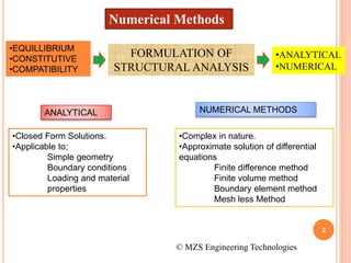
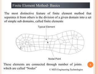
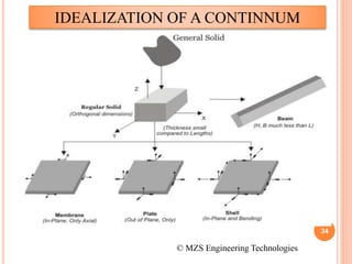

1) The document discusses the basics of the finite element method (FEM), which involves dividing a structure into simple subdomains called finite elements connected at nodes. 2) FEM allows for the analysis of complex problems by replacing differential equations with algebraic equations at nodes. This is done using shape functions to interpolate values within an element. 3) The document compares FEM to other numerical methods like the finite difference method, noting advantages of FEM include better accuracy with fewer elements and the ability to model curved boundaries and nonlinear problems.