Downloaded 85 times
![Kinematics of Machines Friction Drives Unit-V
Yatin Kumar Singh Page 1
Introduction Belt Drives
Usually, power is transmitted from one shaft to another by means of belts, ropes, chains and gears, the salient
features of which are as follows:
1. Belts, ropes and chains are used where the distance between the shafts is large. For small distances, gears
are preferred.
2. Belts, ropes and chains are flexible type of connectors, i.e., they are bent easily.
3. The flexibility of belts and ropes is due to the property of their materials whereas chains have a number of
small rigid elements having relative motion between the two elements.
4 Belts and ropes transmit power due to friction between them and the pulleys. If the power transmitted
exceeds the force of friction, the belt or rope slips over the pulley.
5 Belts and ropes are strained during motion as tensions are developed in them.
6. Owing to slipping and straining action, belts and ropes are not positive type of drives, i.e. their velocity
ratios are not constant. On the other hand, chains and gears have constant velocity ratios.
Belt Drives
To transmit power from one shaft to another, pulleys are mounted on the two shafts. The pulleys are then
connected by an endless belt passing over the pulleys. The connecting belt is kept in tension so that motion of
one pulley is transferred to the other without slip. The speed of the driven shaft can be varied by varying the
diameters of the two pulleys.
For an un-stretched belt mounted on the pulleys, the outer and the inner faces become in tension and
compression respectively. In between there is a neutral section which has no tension or compression. Usually,
this is considered at half the thickness of the belt. The effective radius of rotation of a pulley is obtained by
adding half the belt thickness to the radius of the pulley.
A belt may be of rectangular section, known as Flat Belt [Fig. a] or of trapezoidal section, known as V- Belt
[Fig. b]. In case of a flat belt, the rim of the pulley is slightly crowned which helps to keep the belt running
centrally on the pulley rim. The groove on the rim of the pulley of a V-belt drive is made deeper to take the
advantage of the wedge action. The belt does not touch the bottom of the groove. Owing to wedging action, V-](https://image.slidesharecdn.com/komunit-5-161018084910/85/Friction-Drives-1-320.jpg)
![Kinematics of Machines Friction Drives Unit-V
Yatin Kumar Singh Page 1
Introduction Belt Drives
Usually, power is transmitted from one shaft to another by means of belts, ropes, chains and gears, the salient
features of which are as follows:
1. Belts, ropes and chains are used where the distance between the shafts is large. For small distances, gears
are preferred.
2. Belts, ropes and chains are flexible type of connectors, i.e., they are bent easily.
3. The flexibility of belts and ropes is due to the property of their materials whereas chains have a number of
small rigid elements having relative motion between the two elements.
4 Belts and ropes transmit power due to friction between them and the pulleys. If the power transmitted
exceeds the force of friction, the belt or rope slips over the pulley.
5 Belts and ropes are strained during motion as tensions are developed in them.
6. Owing to slipping and straining action, belts and ropes are not positive type of drives, i.e. their velocity
ratios are not constant. On the other hand, chains and gears have constant velocity ratios.
Belt Drives
To transmit power from one shaft to another, pulleys are mounted on the two shafts. The pulleys are then
connected by an endless belt passing over the pulleys. The connecting belt is kept in tension so that motion of
one pulley is transferred to the other without slip. The speed of the driven shaft can be varied by varying the
diameters of the two pulleys.
For an un-stretched belt mounted on the pulleys, the outer and the inner faces become in tension and
compression respectively. In between there is a neutral section which has no tension or compression. Usually,
this is considered at half the thickness of the belt. The effective radius of rotation of a pulley is obtained by
adding half the belt thickness to the radius of the pulley.
A belt may be of rectangular section, known as Flat Belt [Fig. a] or of trapezoidal section, known as V- Belt
[Fig. b]. In case of a flat belt, the rim of the pulley is slightly crowned which helps to keep the belt running
centrally on the pulley rim. The groove on the rim of the pulley of a V-belt drive is made deeper to take the
advantage of the wedge action. The belt does not touch the bottom of the groove. Owing to wedging action, V-](https://image.slidesharecdn.com/komunit-5-161018084910/75/Friction-Drives-1-2048.jpg)
![Kinematics of Machines Friction Drives Unit-V
Yatin Kumar Singh Page 2
belts need little adjustment and transmit more power, without slip, as compared to flat belts. Also, a multiple
V-belt system, using more than one belt in the two pulleys, can be used to increase the power transmitting
capacity. Generally, these are more suitable for shorter centre distances.
For power transmission by ropes, grooved pulleys are used [Fig. c]. Rope is gripped on its sides as it bends
down in the groove reducing the chances of slipping. Pulleys with several grooves can also be employed to
increase the capacity of power transmission [Fig. d]. They may be connected in either of the two ways:
1. Using a continuous rope passing from one pulley to the other and back again to the same pulley in the next
groove and so on.
2. Using one rope for each pair of grooves.
The advantage of using continuous rope is that the tension in it is uniformly distributed. However, in case of
belt failure, the whole drive is put out of action. Using one rope for each groove poses difficulty in tightening
the ropes to the same extent but with the advantage that the system can continue its operation even if a rope
fails. The repair can be undertaken when it is convenient.
Rope Drives are usually, preferred for long centre distances between the shafts, ropes being cheaper as
compared to belts. These days, however, long distances are avoided and thus the use of ropes has been
limited.
Open and Crossed Belt Drives
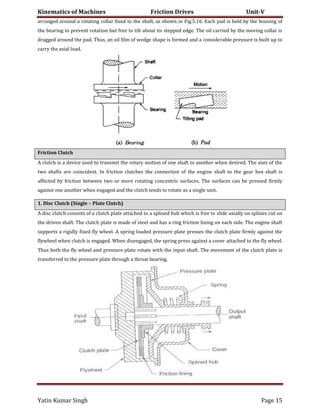
1. Open-Belt Drive
An open belt drive is used when the driven pulley is desired to be rotated in the same direction as the driving
pulley as shown in Fig. Generally, the centre distance for an open-belt drive is 14 to 16 m. If the centre
distance is too large, the belt whips, i.e. vibrates in a direction perpendicular to the direction or motion. For
very shorter centre distances, the bell slip increases. Both these phenomena limit the use of belts for power
transmission.
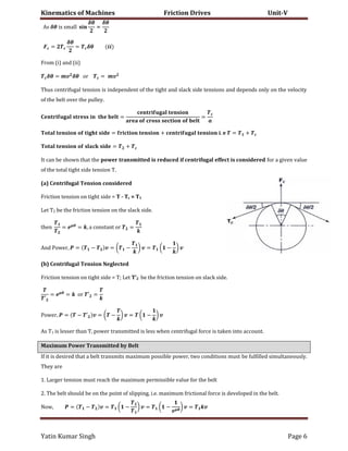
While transmitting power, one side of the belt is more tightened (known as Tight Side) than the other
(known as Slack Side). In case of horizontal drives, it is always desired that the tight side is at the lower side
of two pulleys. This is because the sag of the belt will be more on the upper side than the lower side. This
slightly increases the angles of wrap of the belt on the two pulleys than if the belt had been perfectly straight
between the pulleys. In case the tight side is at the upper side, the sag will be greater at the lower side,
reducing the angle of wrap and slip could occur earlier. This ultimately affects the power to be transmitted.](https://image.slidesharecdn.com/komunit-5-161018084910/85/Friction-Drives-2-320.jpg)
![Kinematics of Machines Friction Drives Unit-V
Yatin Kumar Singh Page 3
2. Crossed-Belt Drive
A crossed-belt drive is adopted when the driven pulley is to be rotated in the opposite direction to that of the
driving pulley.
A crossed-belt drive can transmit more power than an open-belt drive as the angle of wrap is more. However,
the belt has to bend in two different planes and it wears out more.
Velocity Ratio
Velocity ratio is the ratio of speed of the driven pulley to that of the driving pulley.
Let N1 = rotational speed of the driving pulley; N2 = rotational speed of the driven pulley; D1 =diameter of the
driving pulley; D2 =diameter of the driven pulley; t = thickness of the belt
Neglecting any slip between the belt and the pulleys and also considering the belt to be inelastic,
Speed of belt on driving pulley = Speed of belt on driven pulley
( + ) = ( + )
= =
+
+
Slip
The effect of slip is to decrease the speed of belt on the driving shaft and to decrease the speed of the driven
shaft.
Let ω1 = Angular velocity of the driving pulley; ω2 = Angular velocity of the driven pulley; S1 = percentage slip
between the driving pulley and the belt; S2 = percentage slip between the driven pulley and the belt; S = total
percentage slip
���������� ����d �� d����n� �u���y = � (
+
)
����d �� b��� �n ��� d����n� �u���y = [� (
+
)] (
−
)
This is also the speed of the belt on the driven pulley.
���������� ����d �� d����n �u���y = {[� (
+
)] (
−
) (
−
)}
As S is the total percentage slip,](https://image.slidesharecdn.com/komunit-5-161018084910/85/Friction-Drives-3-320.jpg)
![Kinematics of Machines Friction Drives Unit-V
Yatin Kumar Singh Page 4
���������� ����d �� d����n ����� = [� (
+
)] (
−
)
{[� (
+
)] (
−
) (
−
)} = [� (
+
)] (
−
)
− � − �
×
=
− �
− � − � = − �
= + − .
Effect of slip is to reduce the velocity ratio,
= = (
+
+
) (
−
)
Also it is to be remembered that slip will first occur on the pulley with smaller angle of lap i.e. on the smaller
pulley.
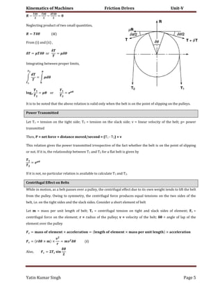
Ratio of Friction Tensions
1. Flat Belt
Let T1 = tension on tight side; T2 = tension on slack side; θ = angle of lap of the belt over the pulley; μ=
coefficient of friction between the belt and the pulley
Consider a short length of belt subtending an angle δθ at the center of the pulley
Let R = normal (radial) reaction between the element length of belt and the pulley
T= Tension on slack side of the element; δT= increase in tension on tight side than that on slack side
T + δT = tension on tight side of the element
Tensions T and (T + δT) act in directions perpendicular to the radii drawn at the ends of the element. The
friction force μR will act tangentially to the pulley rim resisting the slipping of the elementary belt on the
pulley. Resolving the forces in the tangential direction,
� +
��
− + �
��
=
A� �� �� �����
��
≈
� + − − � = �� � = �
Resolving the forces in the radial direction,
−
��
− + �
��
=
A� �� �� �����
��
≈
��](https://image.slidesharecdn.com/komunit-5-161018084910/85/Friction-Drives-4-320.jpg)
![Kinematics of Machines Friction Drives Unit-V
Yatin Kumar Singh Page 10
����� ���c���n�� ����u� �c��n� �n ��� b����n�, = ��. . � ∫ �. � = ��. . . �
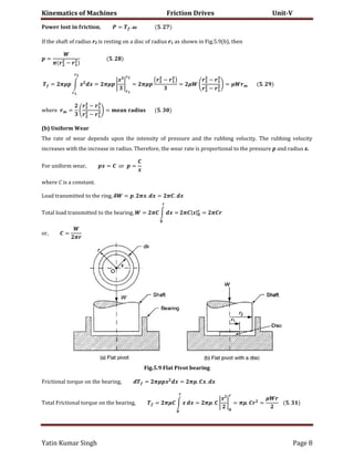
= ( ) � � .
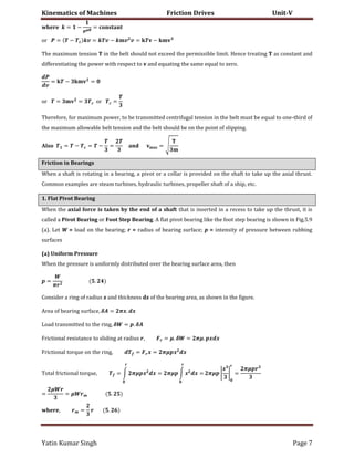
Fig.5.10 Conical pivot bearing
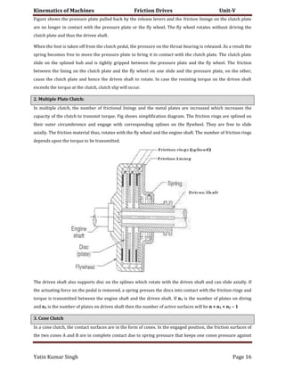
3. Truncated Conical Pivot Bearing
Consider a truncated conical pivot bearing as shown in Fig.5.11. Then
�n��n���y �� un����� �����u�� �� ����n by, =
� −
(a) Uniform Pressure
����� ���c���n�� ����u� �c��n� �n ��� b����n�, = ��. . � ∫ � . � = ��. . �
( − )
= �� [
� −
] .
� ( − )
= ( ) . � . �
−
−
= � . . � .
�����, =
−
−
.
(b) Uniform Wear
����� ���c���n�� ����u� �c��n� �n ��� b����n�, = ��. . � ∫ �. � = ��. . � ( − )
= ��. [
� −
] � ( − ) = � �
+
= � � .](https://image.slidesharecdn.com/komunit-5-161018084910/85/Friction-Drives-10-320.jpg)
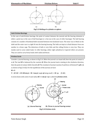

This document discusses belt drives and friction in bearings. It describes the components and functioning of belt drives, including types of belts, pulleys, velocity ratio calculations considering slippage, power transmission, and centrifugal effects. It also covers flat and conical pivot bearings, describing methods to calculate friction forces and wear for uniform pressure and wear distributions. Key points covered include belt material properties, V-belt wedging action, open and crossed belt drive configurations, and friction force calculations for flat and conical bearings.