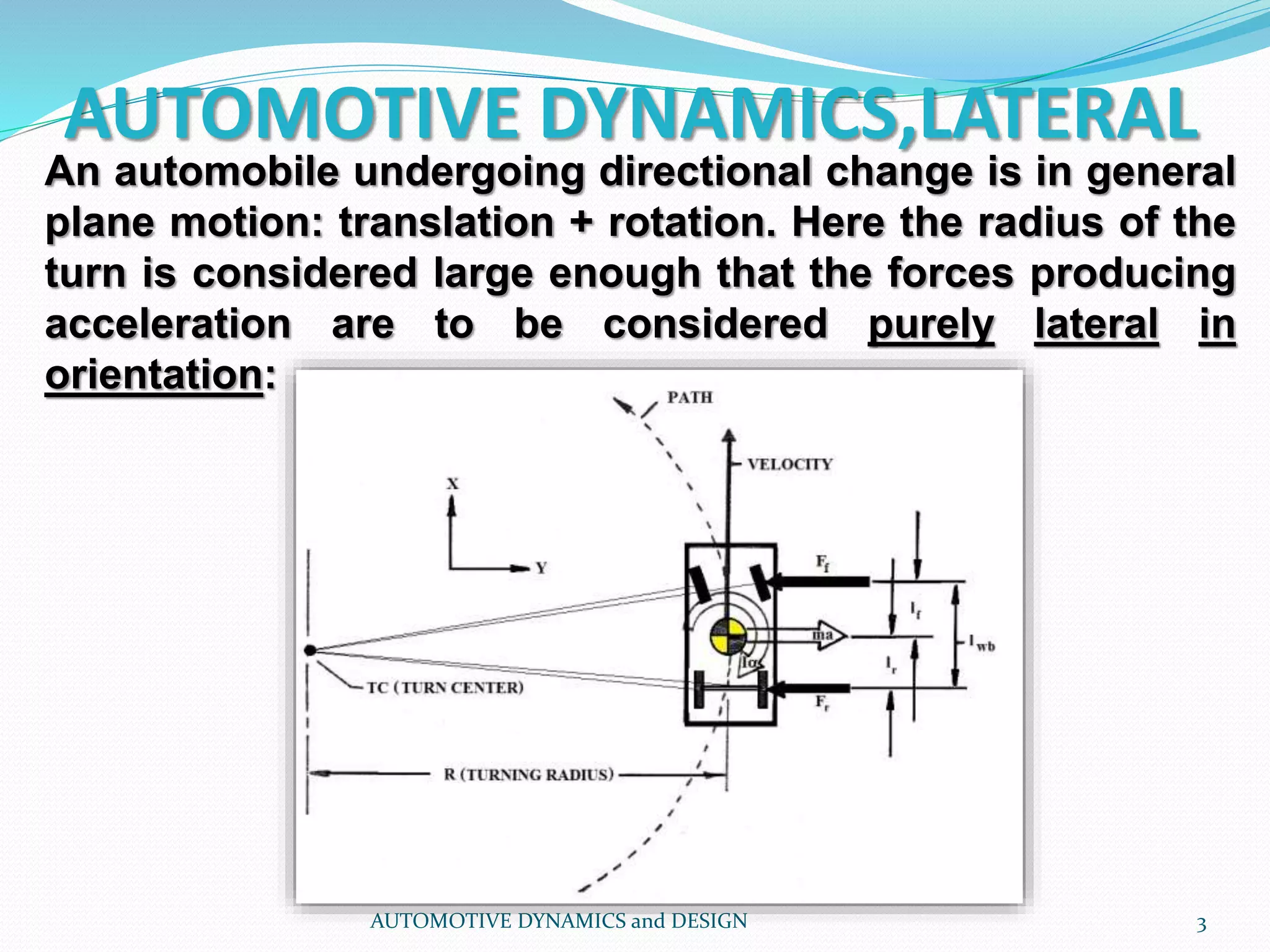
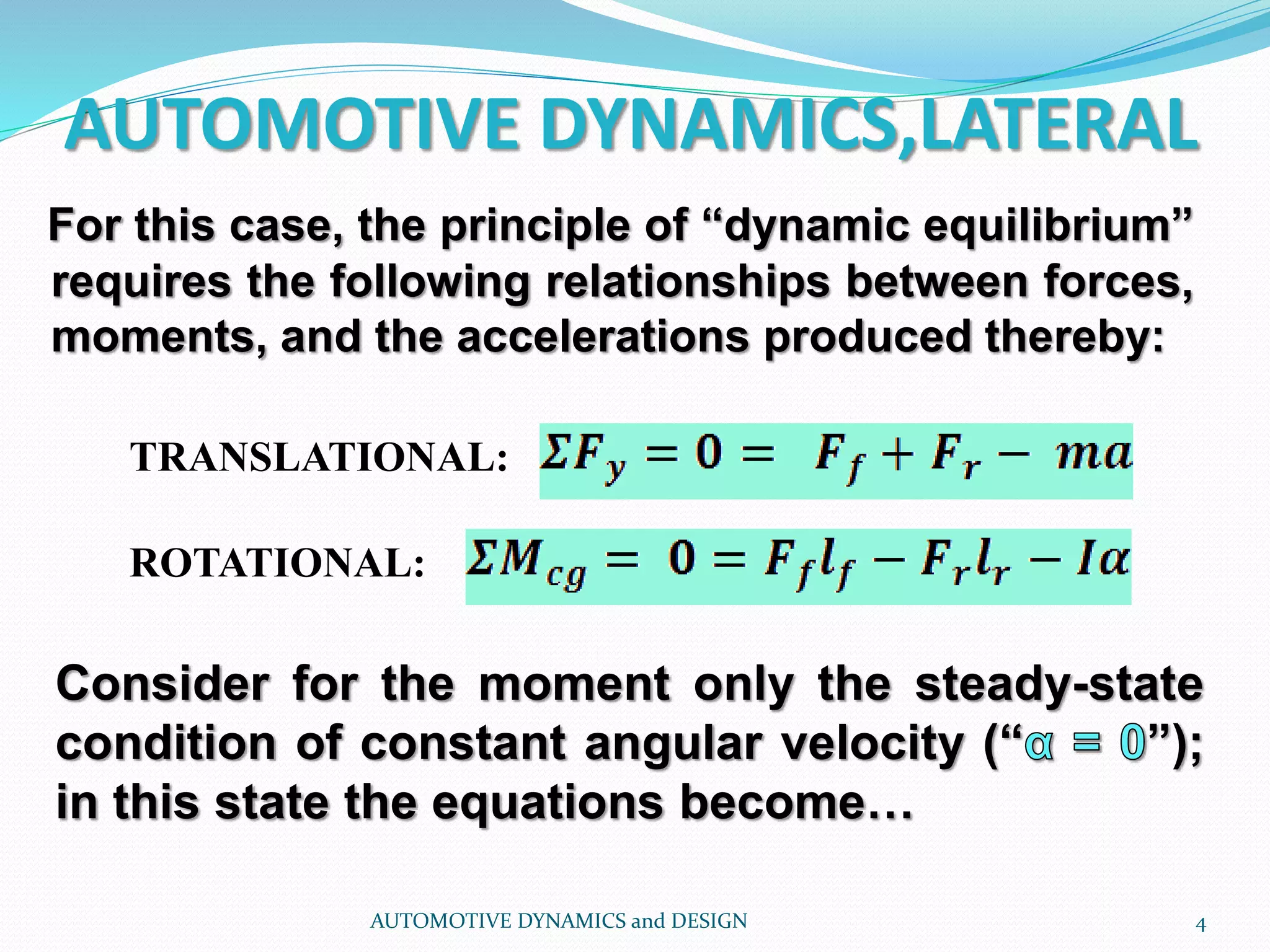
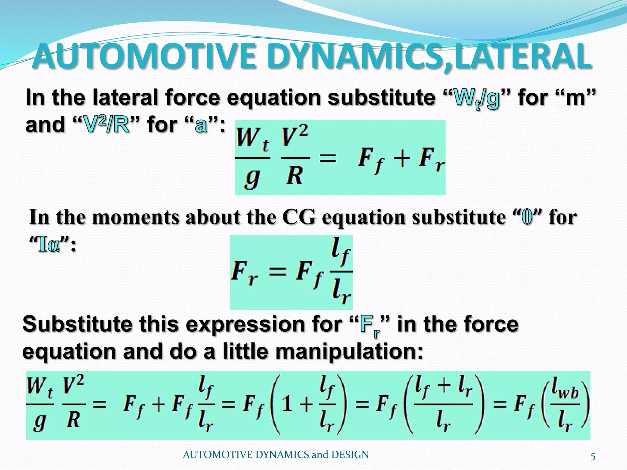
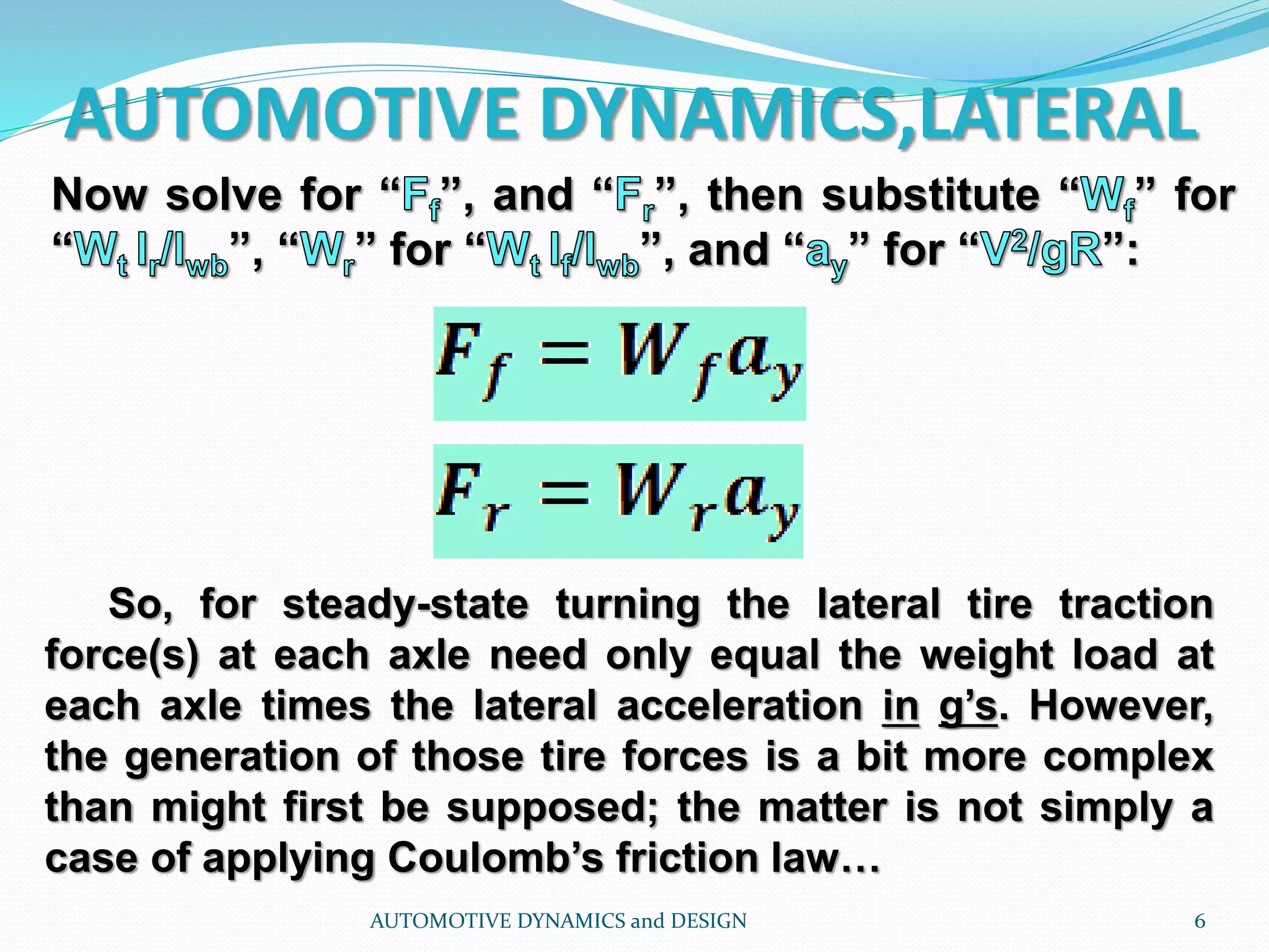
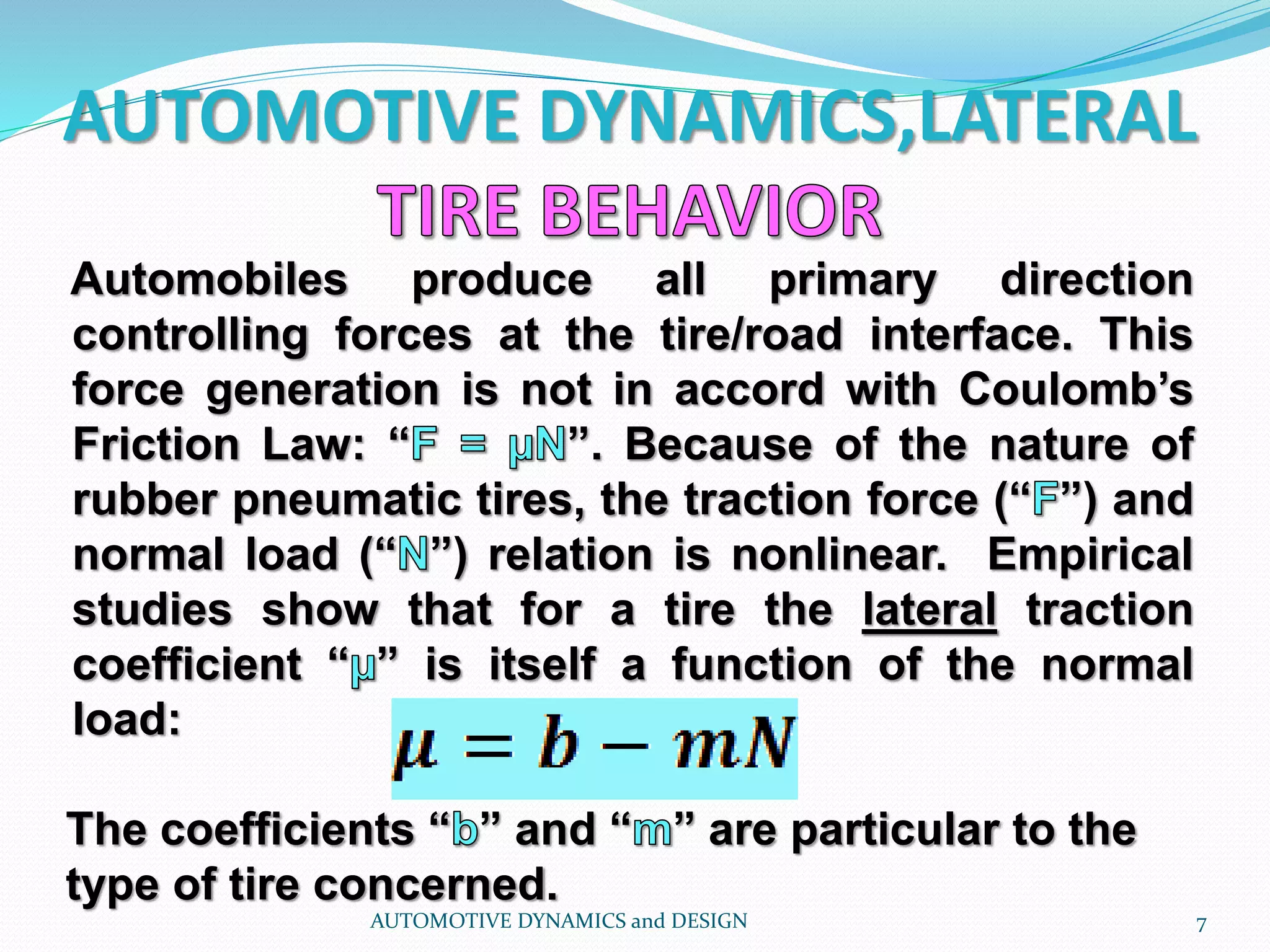
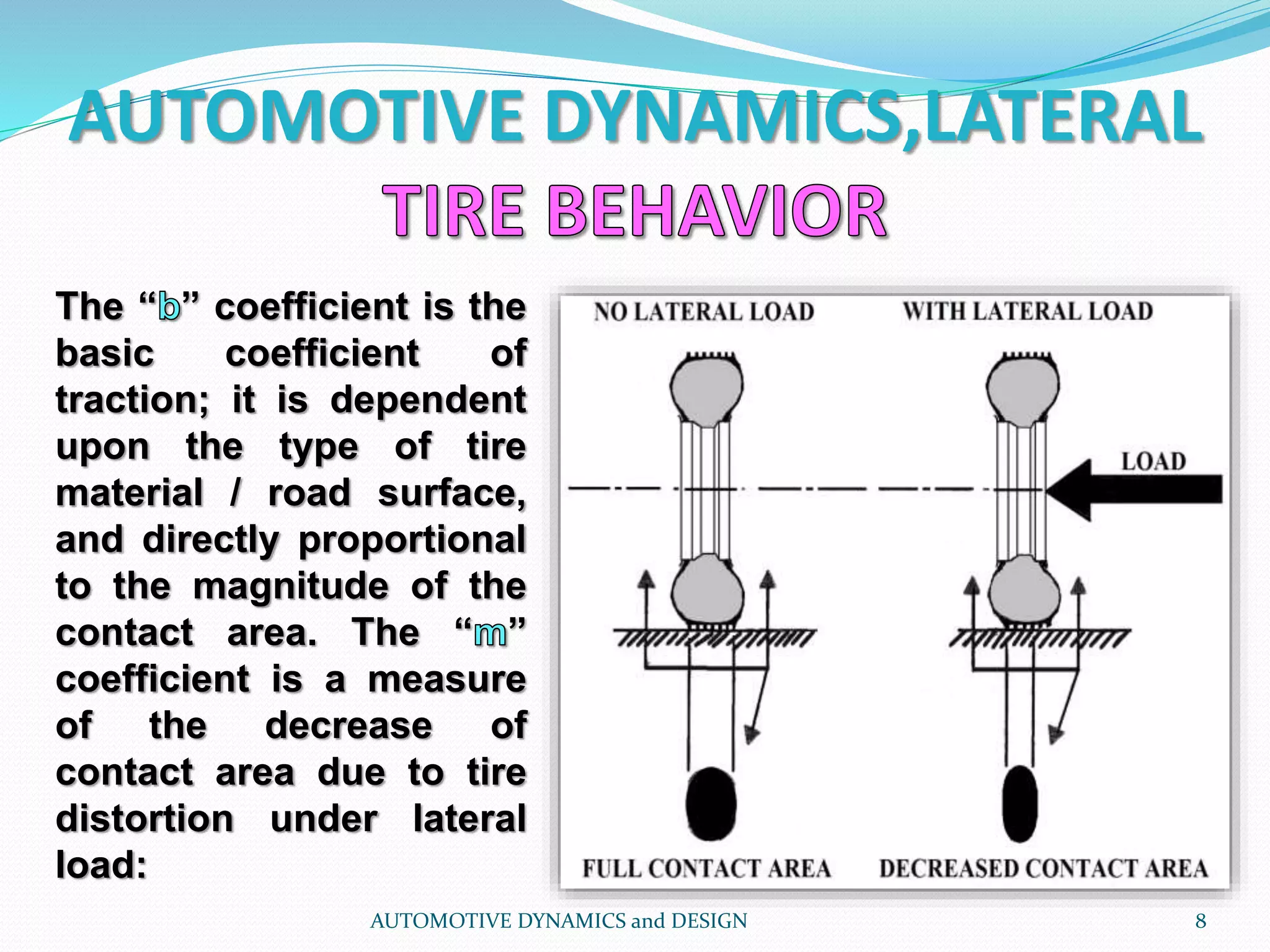
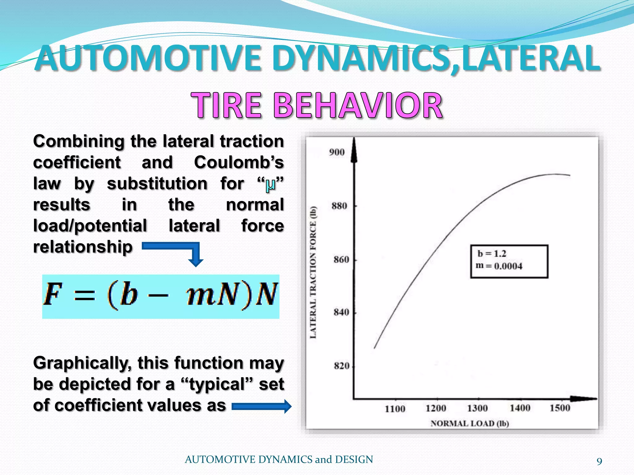
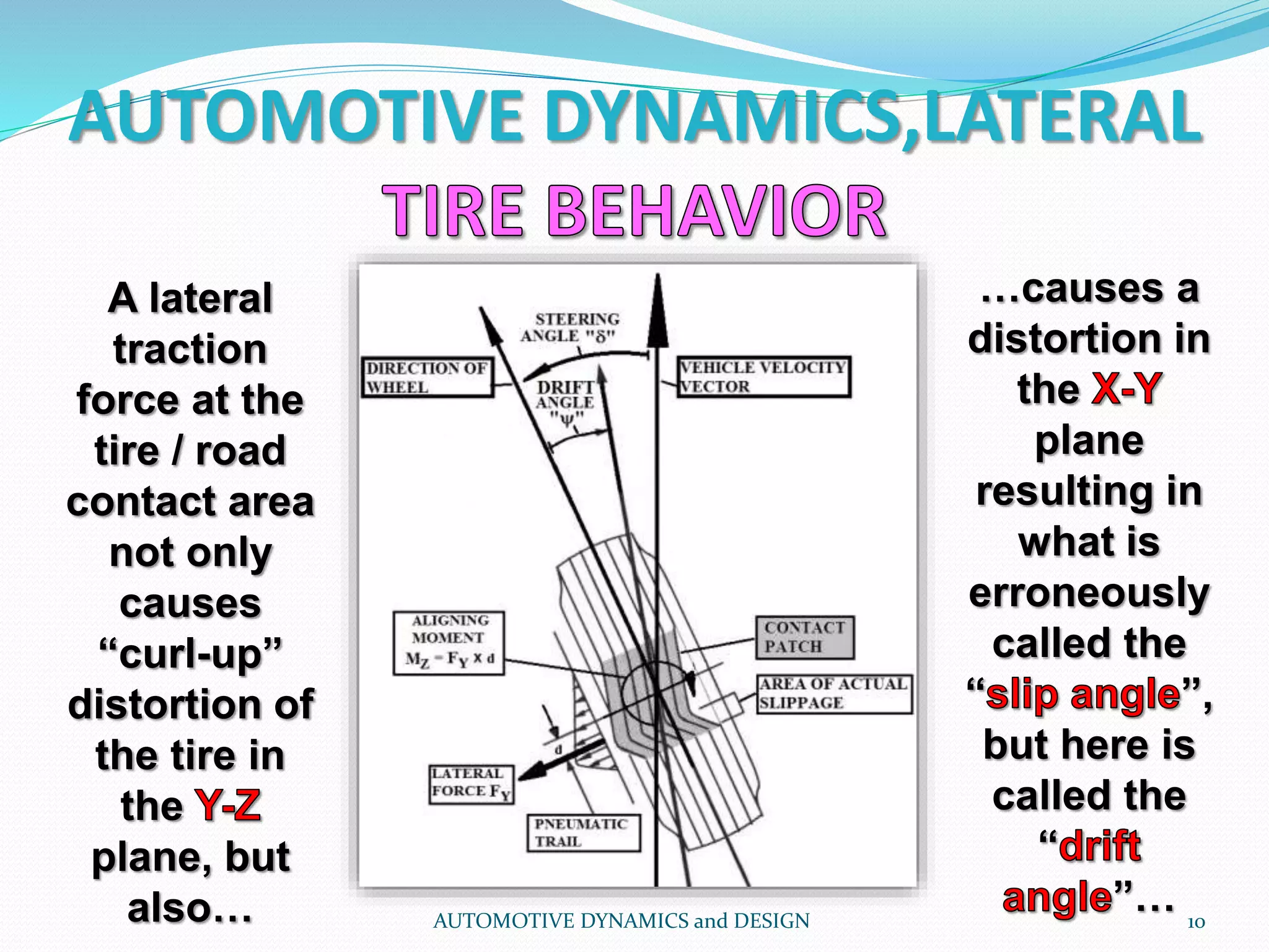
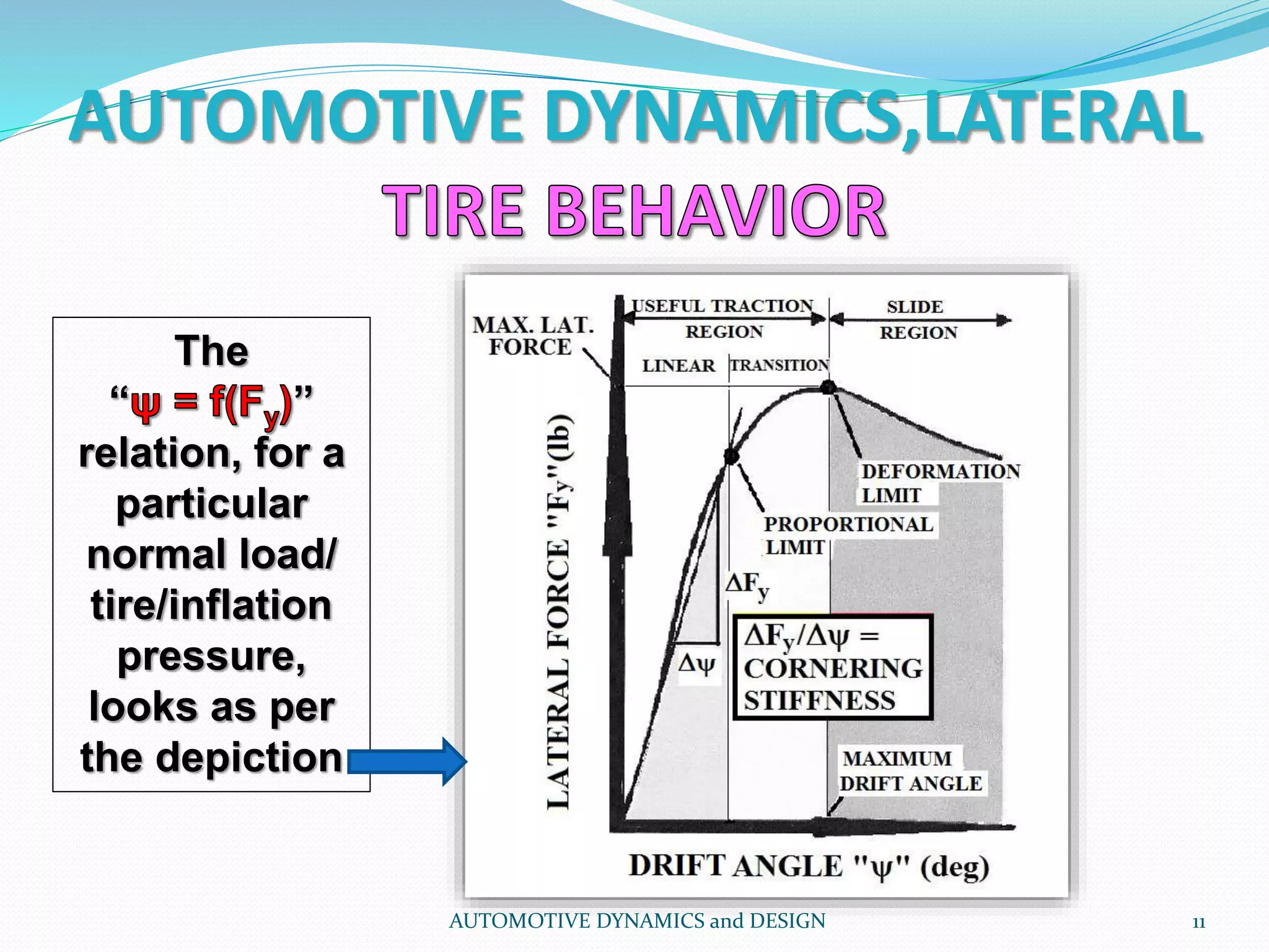
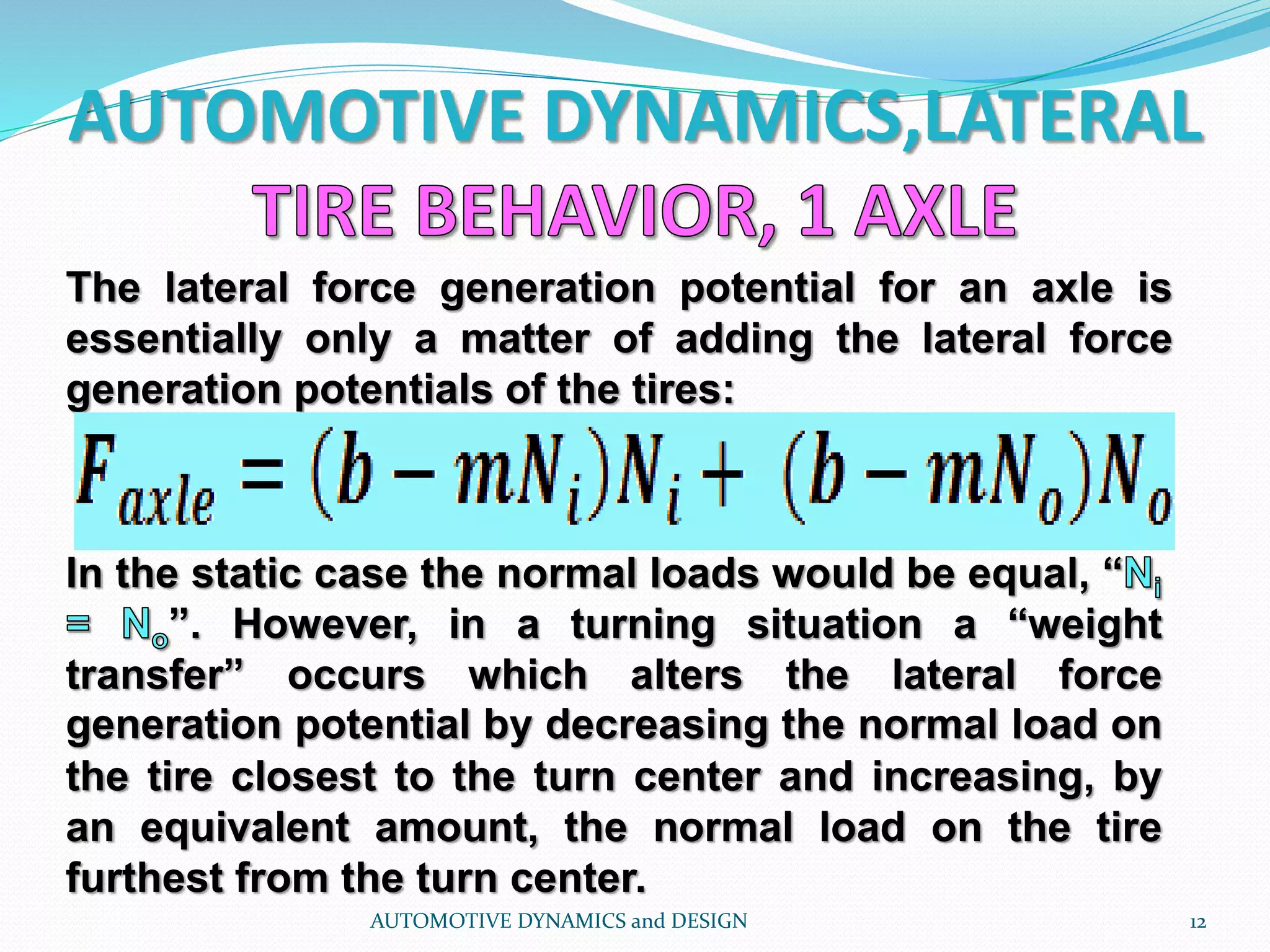
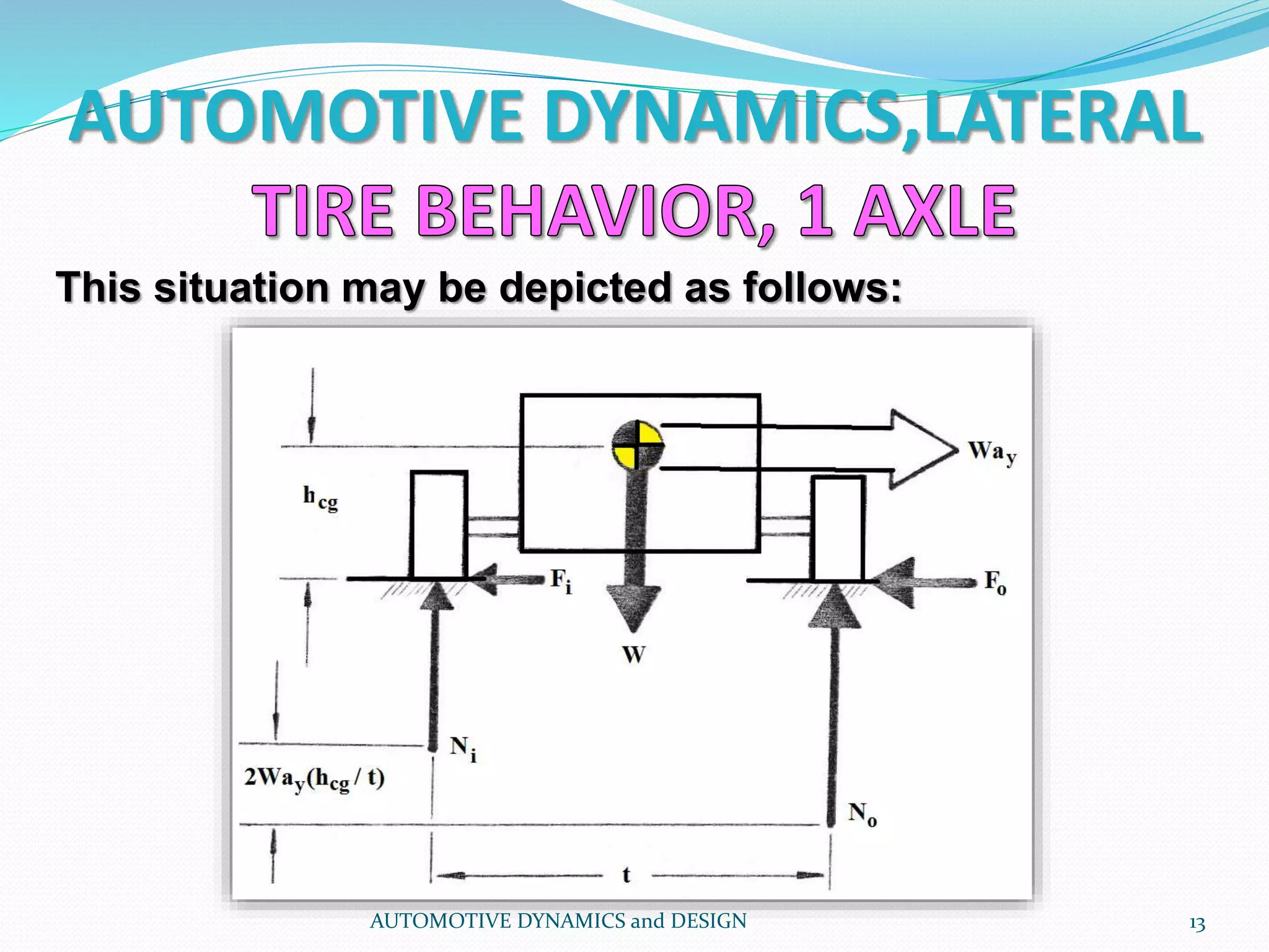
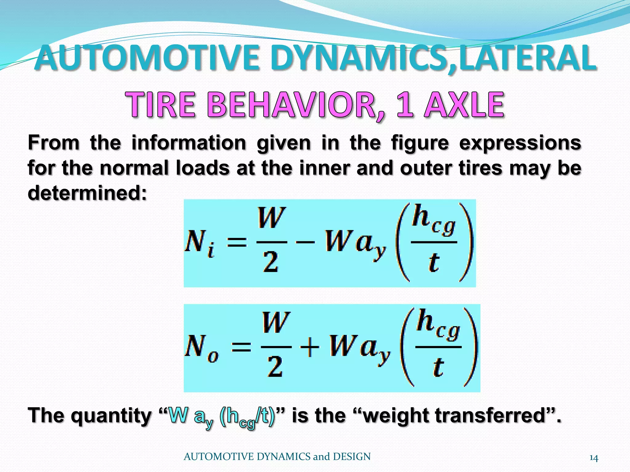
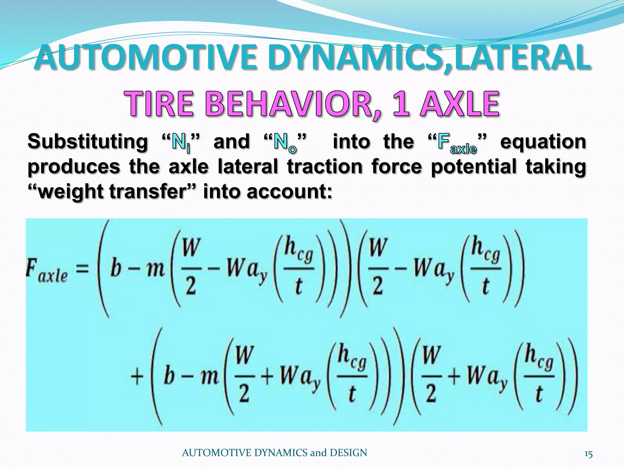
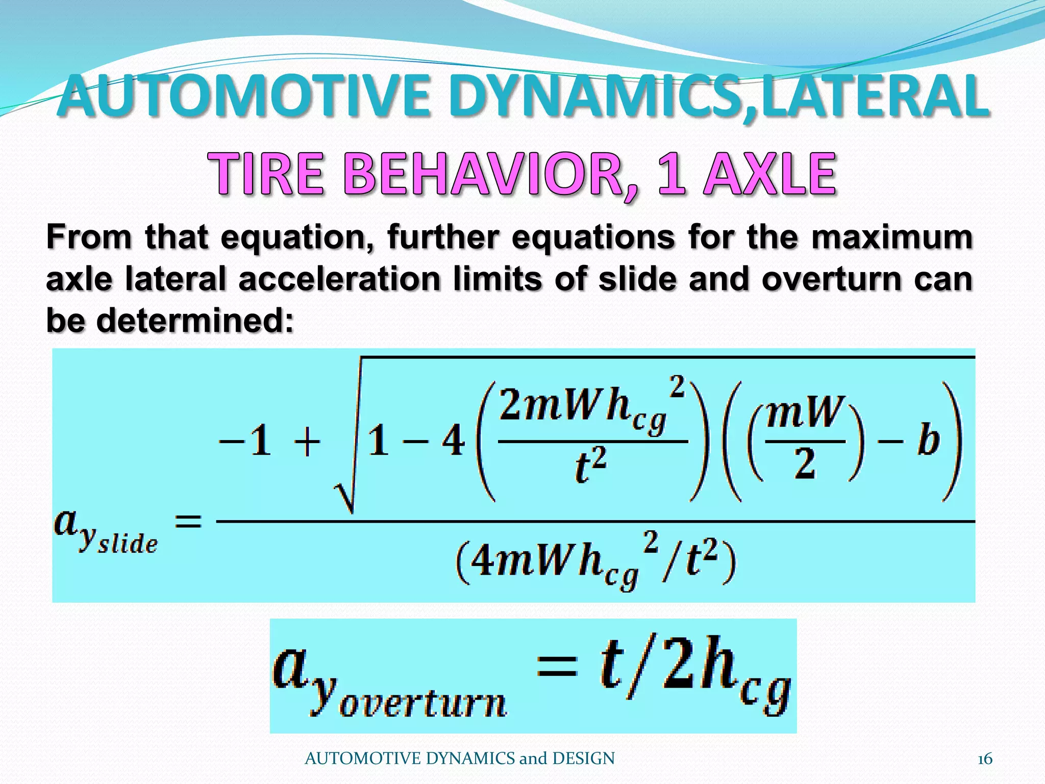
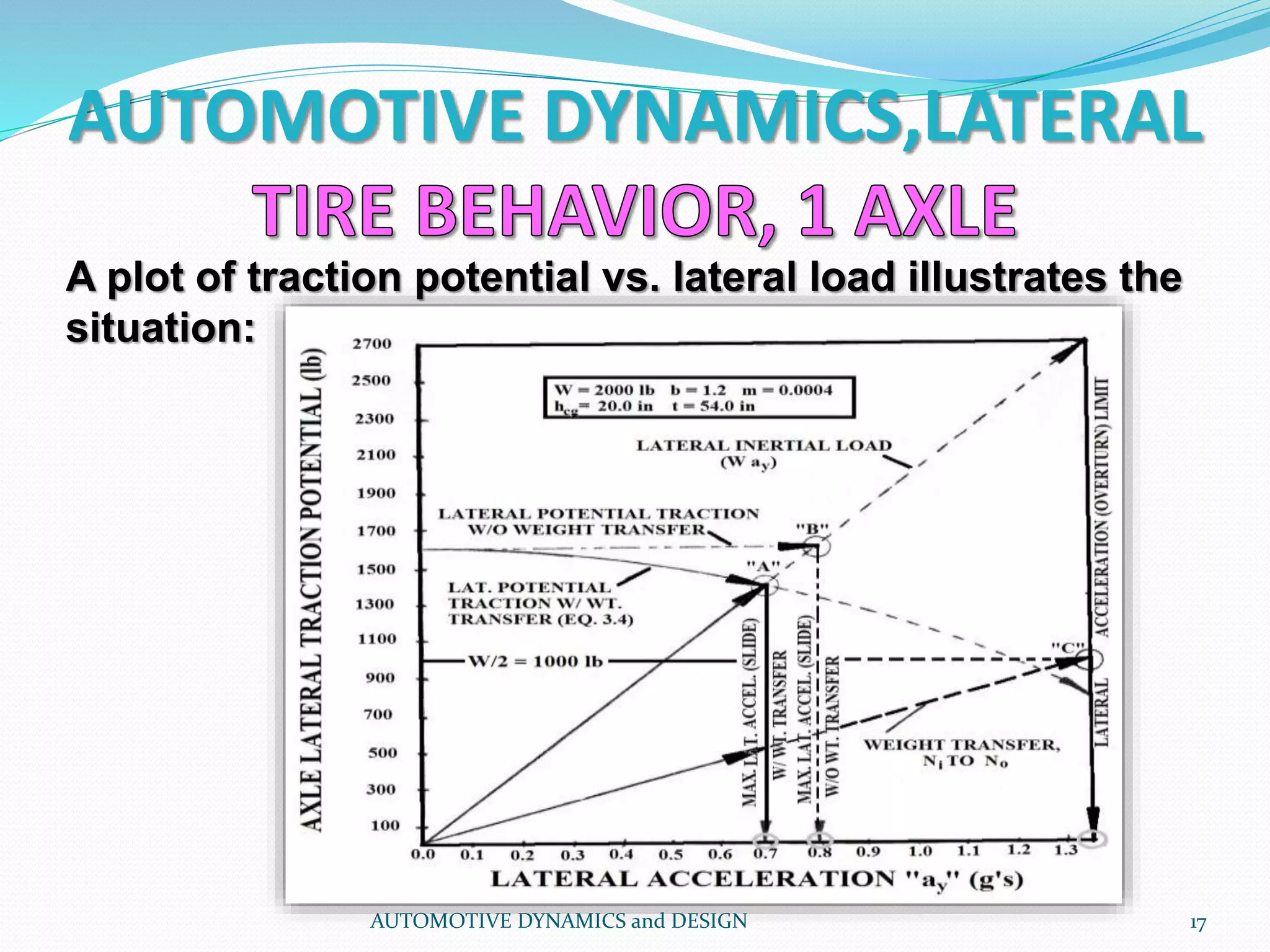
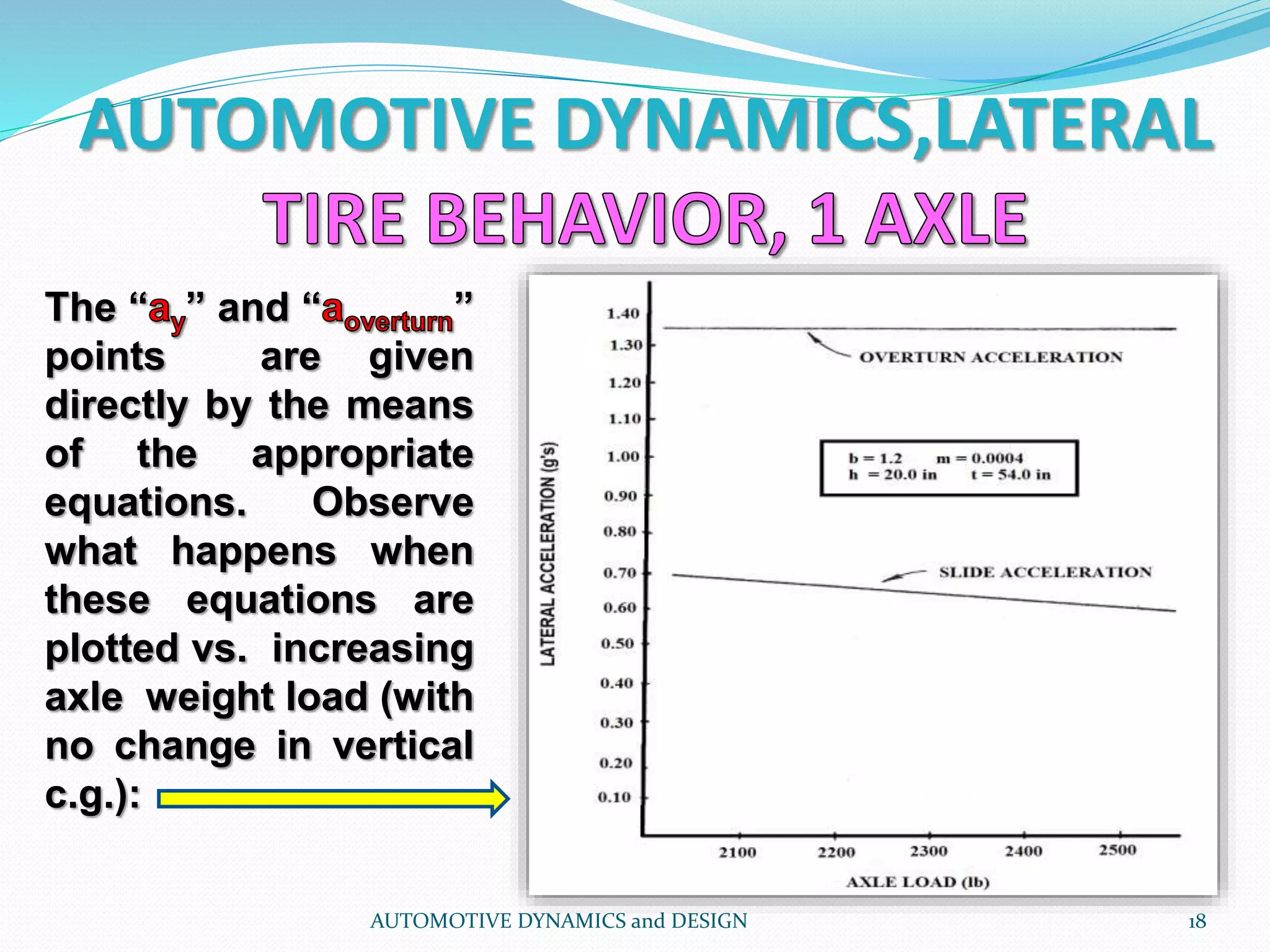
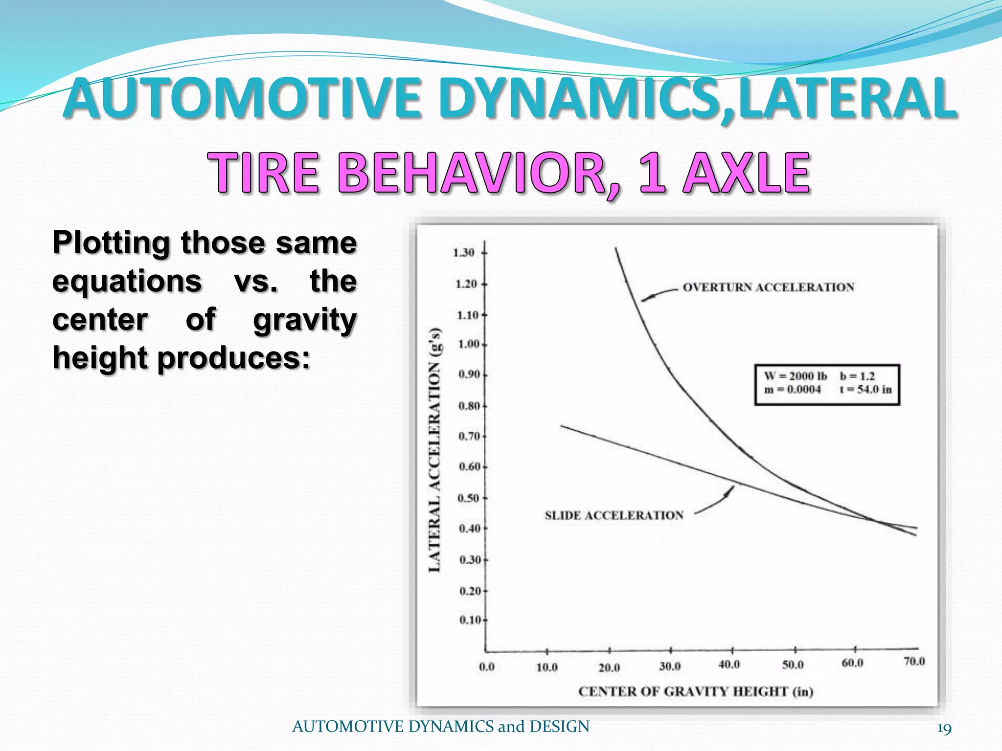
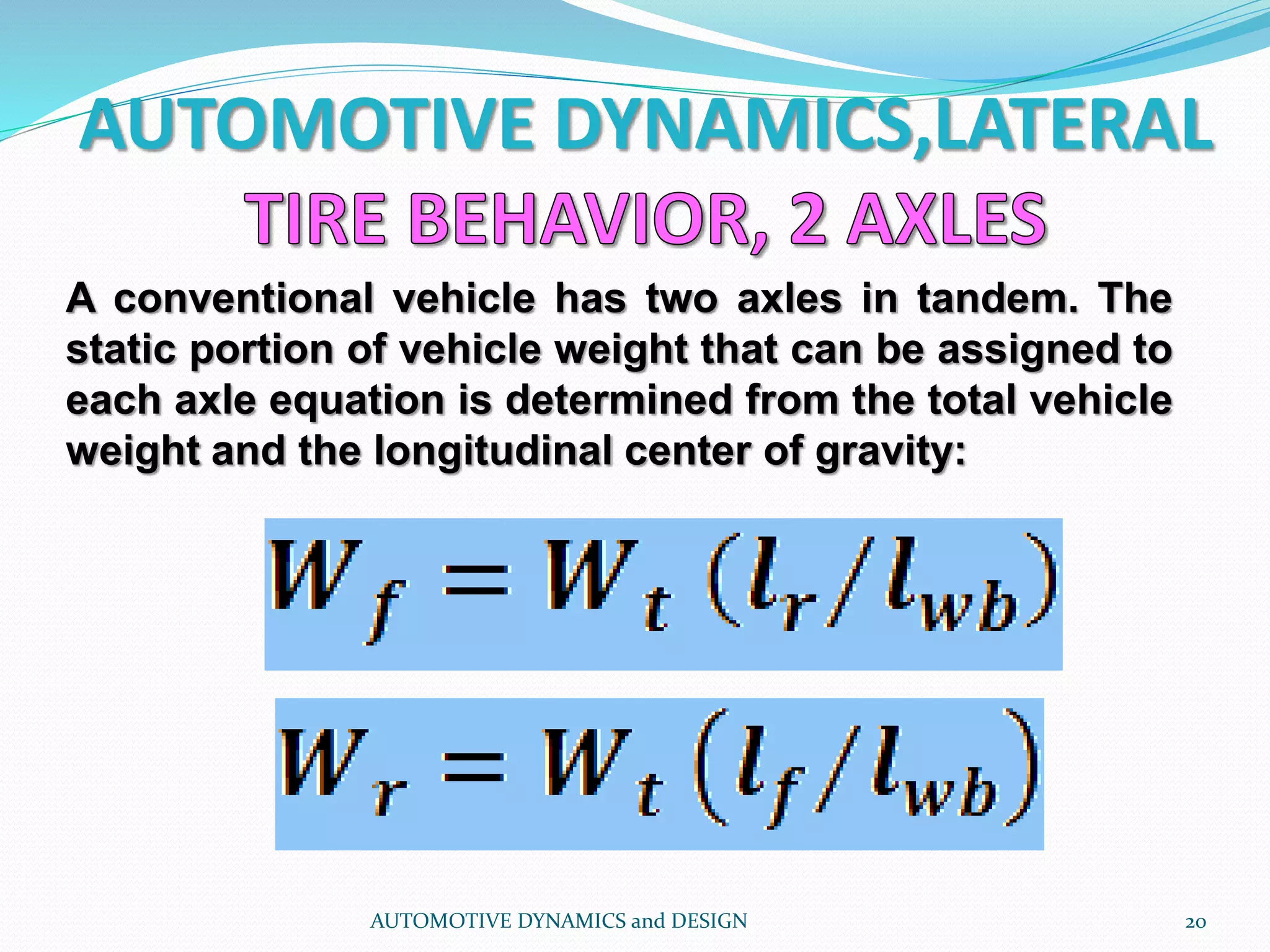
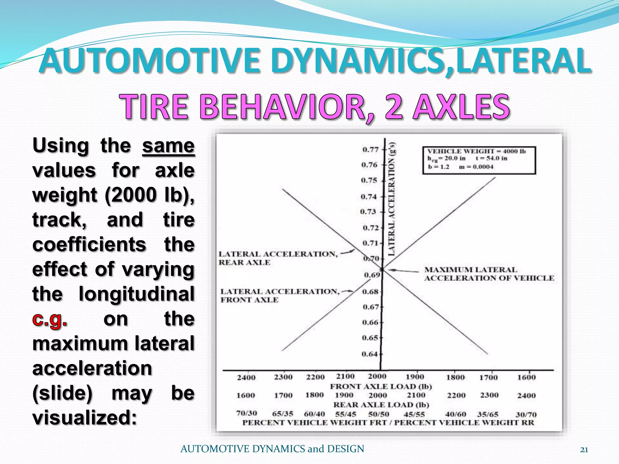
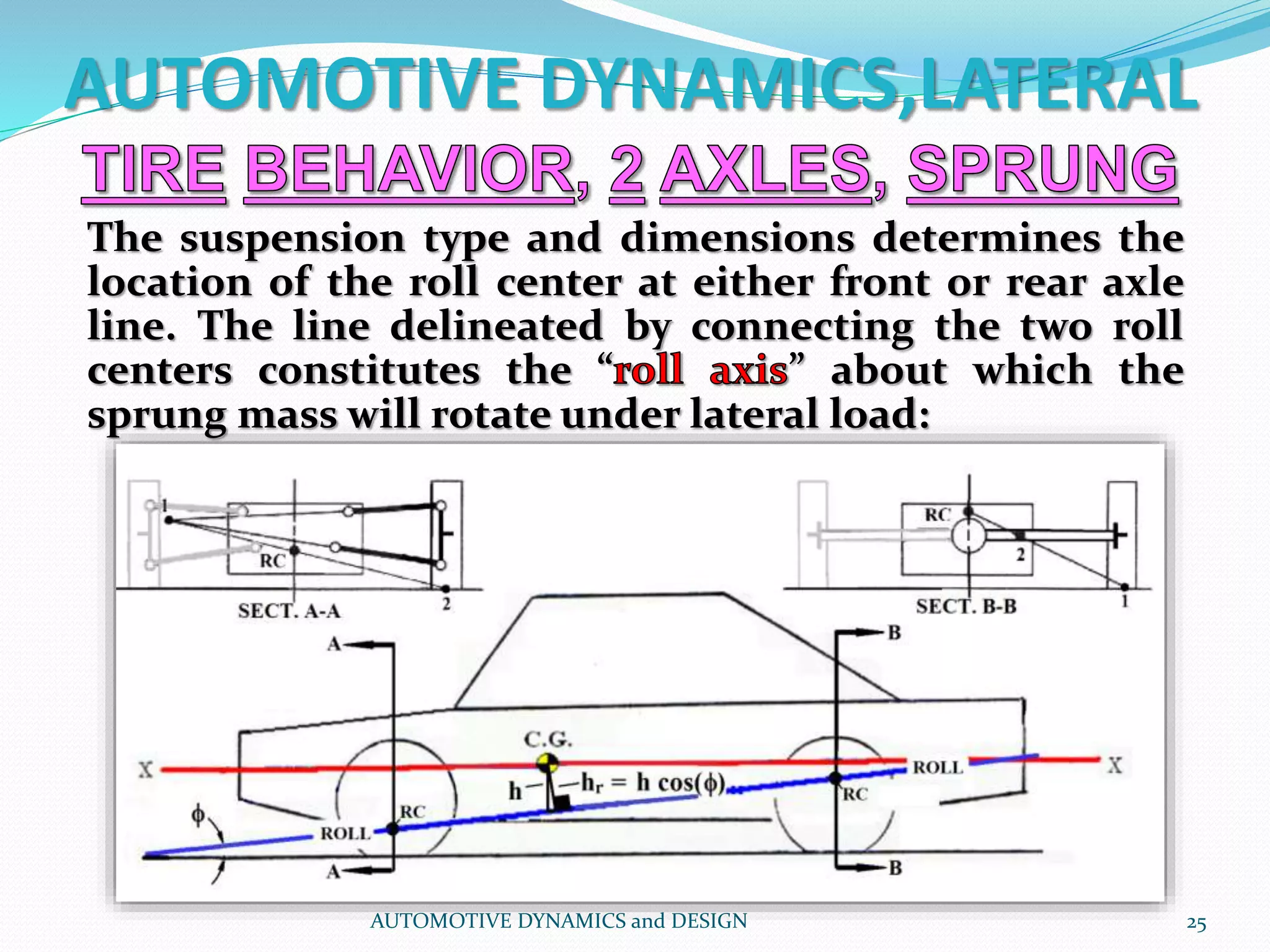
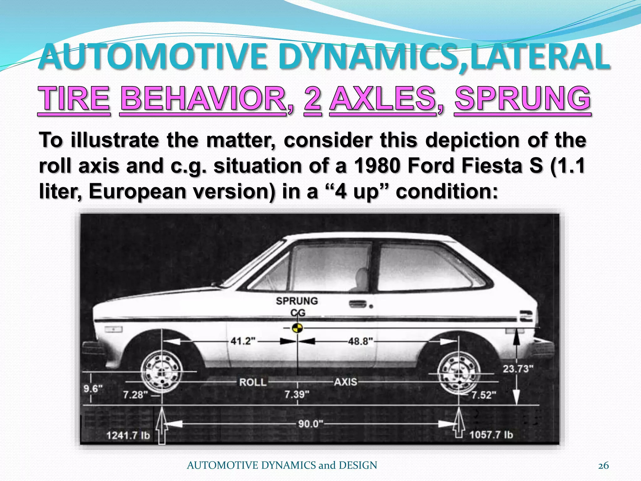
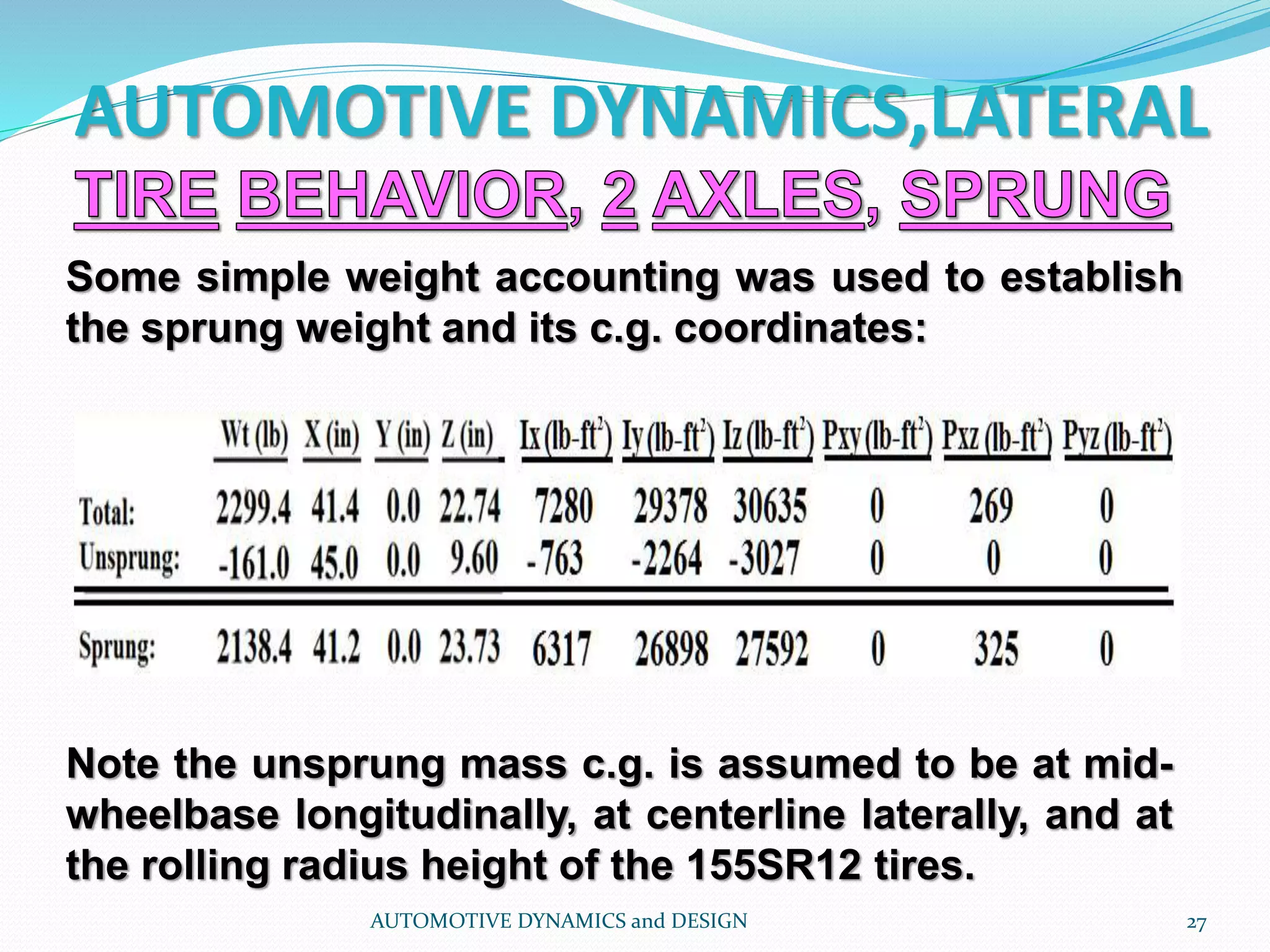
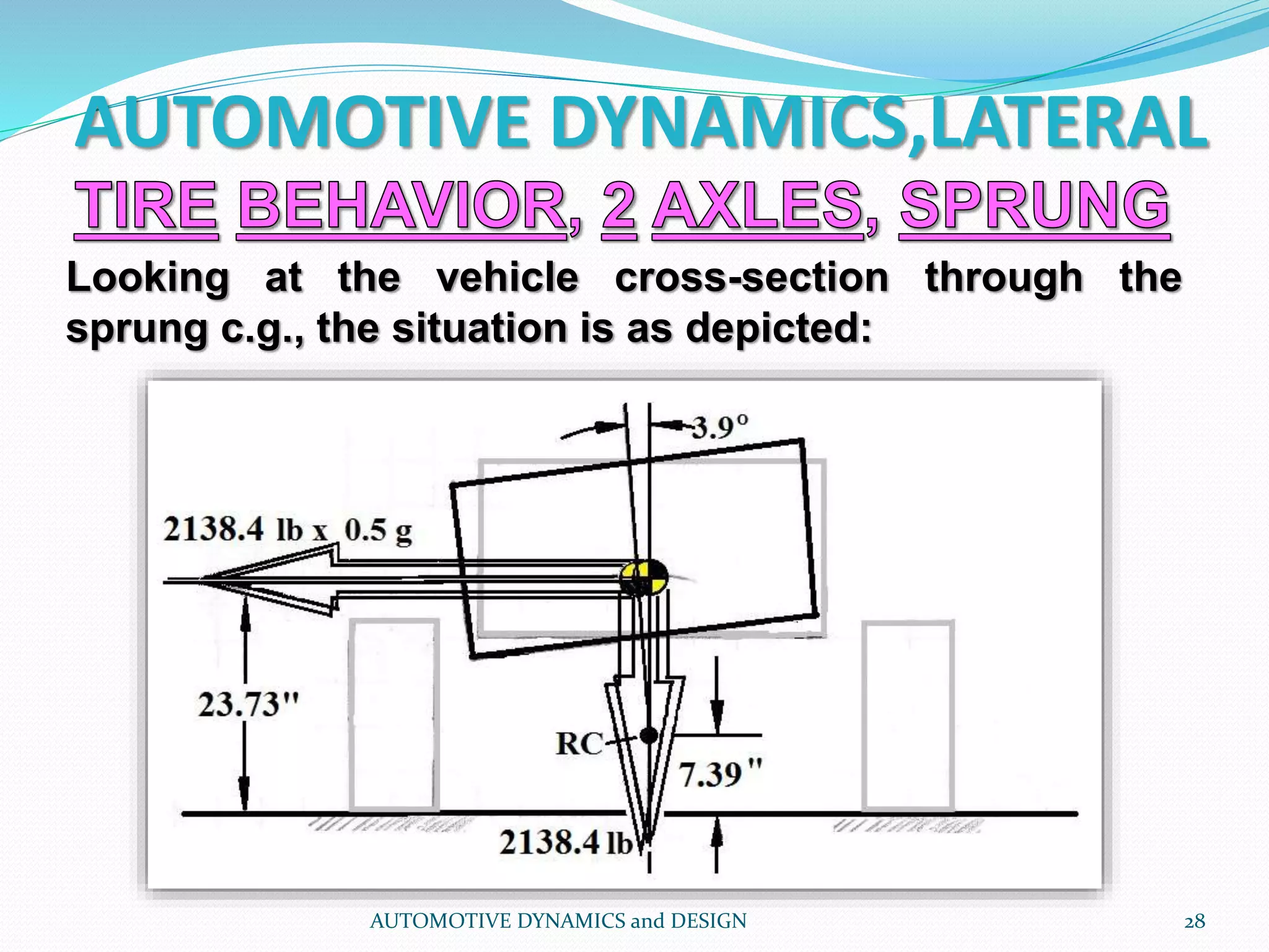
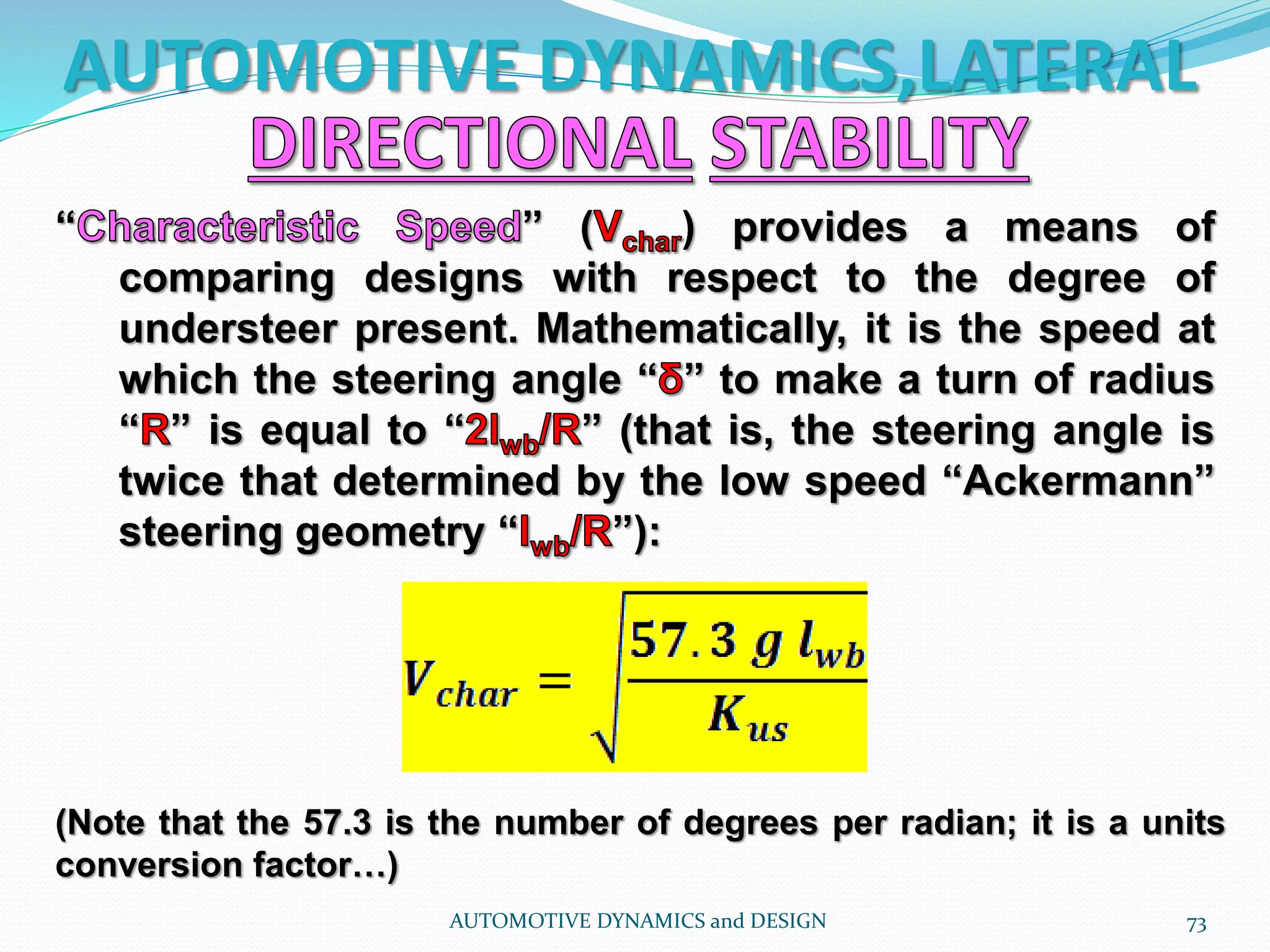
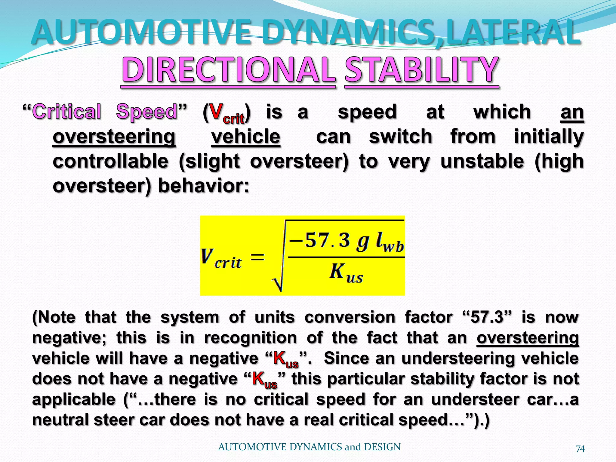
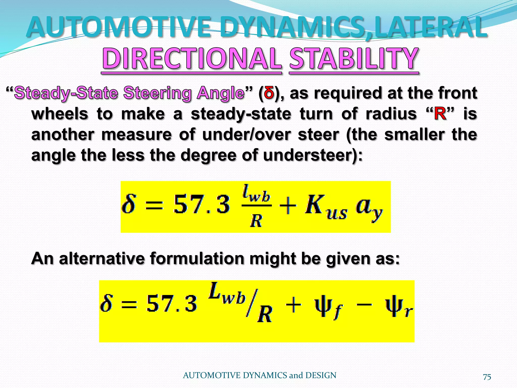
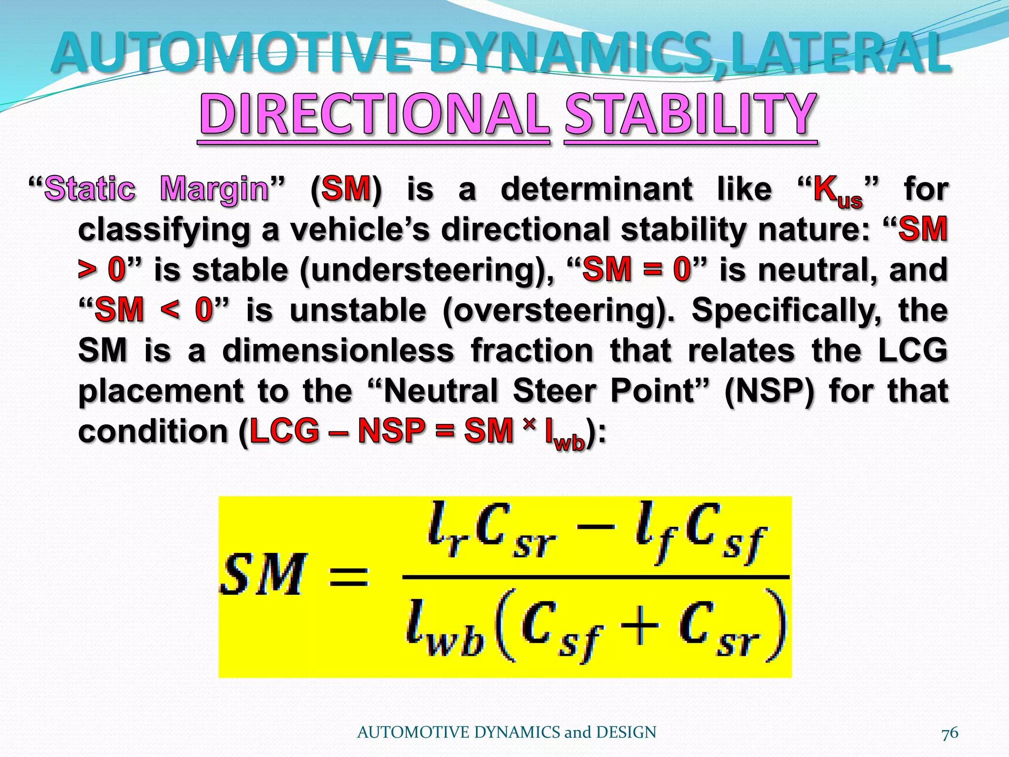
This is Part 3 of a 10 Part Series in Automotive Dynamics and Design, with an emphasis on Mass Properties. This series was intended to constitute the basis of a semester long course on the subject.
crash testing of cars,types of crash testing, how crash testing is done, dummies and its uses in crash testing crash absorption mechanism,safety features in cars
Longitudinal Vehicle Dynamics
-Maximum tractive effort of two-axle and track-semitrailer vehicles.
-The braking force of a two-axle vehicle.
-Acceleration time and distance.
-Relationship between engine torque and thrust force.
-Relationship between engine speed and vehicle speed
basic aerodynamic design consideration of automobile, importance of car aerodyanamic design, various aerodynamic devices use in car body,different tools require for anlysis of aerodynamic
This is Part 4 of a 10 Part Series in Automotive Dynamics and Design, with an emphasis on Mass Properties. This series was intended to constitute the basis of a semester long course on the subject.
Roof Crush Analysis For occupant safety and ProtectionPratik Saxena
Optimization for Roof Crush Analysis under section FMVSS-216. Performed this test on the passenger’s side using Hypermesh and LS-Dyna placed the dummy (Hybrid III 50th percentile), seat, seat belt and side airbag on passenger’s side to perform the analysis. Performed optimization to reduce the chances of injury.
Chassis is the main support structure of the vehicle which is also known as ‘Carrying Unit’. It bears all the stresses on the vehicle in both static and dynamic conditions.”
This is Part 2 of a 10 Part Series in Automotive Dynamics and Design, with an emphasis on Mass Properties. This series was intended to constitute the basis of a semester long course on the subject.
CADmantra Technologies Pvt. Ltd. is one of the best Cad training company in northern zone in India . which are provided many types of courses in cad field i.e AUTOCAD,SOLIDWORK,CATIA,CRE-O,Uniraphics-NX, CNC, REVIT, STAAD.Pro. And many courses
Contact: www.cadmantra.com
www.cadmantra.blogspot.com
www.cadmantra.wix.com
This is Part 8 of a 10 Part Series in Automotive Dynamics and Design, with an emphasis on Mass Properties. This series was intended to constitute the basis of a semester long course on the subject.
Mass Properties and Automotive Braking, Rev bBrian Wiegand
In 1984, for the 43rd Annual International Conference of the SAWE, this author presented Paper Number 1634, “Mass Properties and Automotive Longitudinal Acceleration”. In that paper the effects upon automotive acceleration of varying the relevant mass property parameters were explored by use of a computer simulation. The computer simulation of automotive longitudinal acceleration allowed for the study of each individual parameter because a simulation allows for the decoupling of the parameters in a way that is not possible physically. The principal mass property parameters involved were the vehicle weight and rotating component inertias, collectively known as the “effective mass”, plus the longitudinal and vertical coordinates of the vehicle center of gravity.
However, just as it is important for a vehicle to be able to accelerate, it is perhaps even more important for a vehicle to be able to decelerate. The same mass properties that were relevant to the matter of automotive acceleration are also relevant to the matter of automotive deceleration, a.k.a. braking, although for the braking case that collective of vehicle translational inertia and rotational component inertias known as the “effective mass” requires somewhat different handling. As was the case with automotive acceleration, automotive braking will be explored by use of a computer simulation whereby the effect of variation of each of the mass property parameters can be studied independently. However, this task is considerably easier as the creation of a braking simulation is a minor effort compared to the creation of an acceleration simulation.
Analysis of the stability and step steer maneuver of a linearized vehicle mod...saeid ghaffari
Analysis of the lateral dynamics of the vehicle (stability and step steer manoeuvre) of a Linearized vehicle model with roll motion is done in this project. considering a high double wishbone suspension for front and a semi-trailing arm suspension for rear, firstly we derive the roll camber coefficient and camber stiffness benefiting from a multibody dynamics simulation (MSC ADAMS) validated with experimental values. On the other hand, cornering stiffness and aligning moment are computed through the tire diagrams using Carsim software. Root loci of the system with the objective of investigating the vehicle stability as a function of the vehicle speed is plotted with varying the speed V. Furthermore, a step steer manoeuvre will be performed in which the time history of the variables and the trajectory with respect to the rigid vehicle model will be compared. In the last part, the effect of suspension stiffness and damping variation on the vehicle stability will be examined.
*Only the first ten pages of the project is presented here; if you are interested to study the rest of this document, please do not hesitate to contact e via saeid.ghaffari@studenti.polito.it.
“Computer based wireless automobile wheel alignment system using accelerometer” scientific paper, as published at “The International Journal of Engineering and Science (IJES)”, Volume 4, 2015 by Sonali Chatur
TYRE WEAR
Tidy shoes just don't give an appearance boost but also underline the ground grip; somewhat analogous to tyre in vehicles.
Rolling wheels have always been a very dynamic subject to deal with. Apart from regular maintenance of the vehicle, tyre wear is a major point of concern for every automotive owner . Its more dear in the commercial segment . Its second largest element of cost of operation after fuel . Truck , bus , fleet owners or any commercial vehicle driver - carrier - owner would always be keen on getting tyre life irrespective how he drives and loads .
A considerable research has been done in tyre tread wear with
respect to road friction but still the suspension parameters and
steering arrangements are in phase on development. There is no evidence to suggest that certain types of suspensions or steering arrangements have any particular adverse impact on tire life, it's more of a perception than factuality.
We are trying to build an analytical / illustrative module which
explains the appropriate relationship between all geometric parameters and tire life in particular irregular tyre wear. This is been accomplished by varying the geometric angles and tracing their effect on tread wear. Archard' theory been the base of this research work we have sorted some equations, but still some parameters are not accounted altogether. For ex., while calculating the varying toe and camber angles temperature or global contact points remain unaccounted. And still some uncertainties remain regarding the friction coefficients.
The objective is to build an model which can explain and hence suggest correction to reduce tyre wear and enhance life. While its complex with varying geometry under various speeds, loads & road condition .
All leads are appreciated.
Stability analysis of a Rigid Vehicle Modelsaeid ghaffari
The lateral stability of a two axle vehicle with open loop control will be studied in this project. A 3 dof model is adopted to evaluate the curvature gain and the root loci as a function of the vehicle speed V. Moreover, the dynamic response of the vehicle considering the step steer manoeuvre will be analysed according to the ISO norm. The side slip angle and the yaw rate are evaluated as a function of time, while the trajectory of the center of gravity G of the vehicle with respect to the inertial reference frame (OXY Z) is plotted during step steer maneuver. Inasmuch as the change of cornering stiffness on tires due to the different condition are small, we cannot see the difference between the trajectories, shedding light on the steering angles, however, we can understand what is happening in various conditions. In this study, both the effect of traction force on the front and rear axle and transversal load transfer on the front and rear axle are investigated.
*only the first 10 pages of the main project are presented here. If you are interested to go through the rest of this document please contact me via saeid.ghaffari@studenti.polito.it.
Computer based Wireless Automobile Wheel Alignment system using Accelerometertheijes
A computer based wireless automobile wheel alignment measurement system using accelerometer is presented in this paper, which has the advantages of simple circuit, low cost , high resolution with high working reliability. The causes and effects of improper wheel alignment by traditional methods are analyzed in the model. In this system wireless transmission techniques are adopted to transmit data between measuring unit and computer. This makes the measurement operation much easier. This paper presents unique and innovative use of accelerometer for the measurement of automobile wheel parameters, such as camber and toe. The hardware and software realizations are also explored in this paper. The system practical applications shows that its performance meets the design requirements.
Kinematics and Compliance of Sports Utility VehicleIRJEETJournal
Today, we have to consider different demands to make a successful and reliable concept design of modern suspension systems. Beside package and lightweight construction especially the real scopes of a suspension system, kinematics and compliances are getting more and more important to fulfill all the technical needs coming from the automotive market. In particular, the development of suspension system for sport utility vehicle (SUVs) has to satisfy various demands and strong characteristic criteria coming from the on-road and off-road driving conditions.
In this paper, the main kinematics and compliance effects for an independent SUV suspension system will be explained and illustrated:
Explanation of different load cases coming from the individual purpose of a sport utility vehicle (off road & on road)
- Illustration of the K&C influences coming from the use of active systems to control roll and pitch angles or the individual wheel loads
- Development of an analytic approach to solve the kinematic and compliance needs.
- Simulation description and results to verify the suspension design.
- Analysis of vibration problems resulting from suspension concepts.
Similar to 3- AUTOMOTIVE LATERAL DYNAMICS, Rev. A (20)
Mass properties and automotive lat accel presentation, rev aBrian Wiegand
This presentation accompanied the delivery of SAWE Paper #3528 at the 70th International Conference of the SAWE at Houston, TX, USA during May 2011.
There are a number of automotive performance aspects which are associated with accelerations in the lateral direction: maneuver (transient and steady state), roll-over, and directional stability. For each of these automotive performance aspects certain mass property parameters play significant roles; it is the intent of this presentation to make explicit exactly how those mass property parameters affect each of those automotive performance aspects.
MASS PROPERTIES and AUTOMOTIVE CRASH SURVIVAL, Rev. ABrian Wiegand
This presentation accompanied the delivery of SAWE Paper #3634 at the 74th SAWE International Conference held from May 18 to 21, 2015, at the Crown Plaza Hotel in Alexandria, VA, USA.
The purpose of this paper was to make explicit the exact role that mass properties play in determining the automotive deceleration performance during a crash. This has a direct bearing on the survivability of a crash, which can be enhanced through thoughtful mass properties engineering.
This is Part 10 of a 10 Part Series in Automotive Dynamics and Design, with an emphasis on Mass Properties. This series was intended to constitute the basis of a semester long course on the subject.
This is Part 9 of a 10 Part Series in Automotive Dynamics and Design, with an emphasis on Mass Properties. This series was intended to constitute the basis of a semester long course on the subject.
This is Part 7 of a 10 Part Series in Automotive Dynamics and Design, with an emphasis on Mass Properties. This series was intended to constitute the basis of a semester long course on the subject.
This is Part 6 of a 10 Part Series in Automotive Dynamics and Design, with an emphasis on Mass Properties. This series was intended to constitute the basis of a semester long course on the subject.
MASS PROPERTIES and AUTOMOTIVE DIRECTIONAL STABILITYBrian Wiegand
The quantification of automotive directional stability may be expressed through various stability metrics, but perhaps the most basic of these automotive stability metrics is the “Understeer Gradient” (Kus). The Understeer Gradient (in degrees or radians per unit gravity) appears extremely uncomplicated when viewed in its most common formulation.
This metric appears to depend only on the front and rear axle weight loads (Wf, Wr), and on the front and rear axle cornering stiffnesses (Csf, Csr). However, those last quantities vary with lateral acceleration, and the nature of that variation is dependent upon many other parameters of which some of the most basic are: Total Weight, Sprung Weight, Unsprung Weight, Forward Unsprung Weight, Rear Unsprung Weight, Total Weight LCG, Sprung Weight LCG, Total Weight VCG, Sprung Weight VCG, Track, Front Track, Rear Track, Roll Stiffness, Front Roll Stiffness, Rear Roll Stiffness, Roll Axis Height, Front Roll Center Height, and Rear Roll Center Height. Note that exactly half of these automotive directional stability parameters as listed herein are mass properties.
The purpose of this paper is to explore, through a skidpad simulation, the relative sensitivity of automotive directional stability (as quantified through the Understeer Gradient) to variation in each of the noted vehicle parameters, with special emphasis on the mass property parameters.
The simulation is constructed in a spreadsheet format from the relevant basic automotive dynamics equations; the normal and lateral loads on the tires are determined as the lateral acceleration is increased incrementally by a small amount (thereby maintaining a “quasi-static” or “steady-state” condition). The normal loads are used for the calculation of the lateral traction force potentials at each tire, with the required (centripetal) lateral traction forces apportioned accordingly. From those required (actual) lateral tire forces the corresponding tire cornering stiffnesses are determined; this determination is based upon a tire model developed through a regression analysis of tire test data.
This construction of a fairly comprehensive lateral acceleration simulation from basic automotive dynamic relationships, instead of depending upon commercial automotive software such as “CarSim” (vehicle model) and Pacjeka “Magic Formula” (tire model), constitutes a unique aspect of this paper; this return to basics hopefully provides a clearer view and understanding of the results than would be the case otherwise. Even more unique is this paper’s emphasis on, and exploration of, the role specific mass property parameters play in determining automotive directional stability.
5- MASS PROPERTIES ANALYSIS and CONTROL Brian Wiegand
This is Part 5 of a 10 Part Series in Automotive Dynamics and Design, with an emphasis on Mass Properties. This series was intended to constitute the basis of a semester long course on the subject.
IT IS BECAUSE VEHICLE DYNAMICS IS SO DEPENDENT ON MASS PROPERTIES THAT AN ENTIRE ENGINEERING DISCIPLINE IS DEVOTED TO “MASS PROPERTIES ANALYSIS & CONTROL”. THIS CLASS PRESENTATION WAS CREATED WITH THE INTENT TO ACQUAINT THE STUDENT WITH THE BASIC MATHEMATICS UNDERLYING THE PRACTICE OF "MASS PROPERTIES ANALYSIS AND CONTROL".
It wasn't so long ago that, while President Ronald Reagan presided, the "Evil Empire" of the Soviet Union collapsed. But, while the empire collapsed, the evil lived on. Today, the evil nucleus of that fallen empire, Russia, is more dangerous than ever with a greatly enlarged and active covert secret service effort. That effort is being expended to undermine western democracies so as to neutralize them in a bid to regain its empire, if not even more. Since the useful ideology of "Communism" collapsed along with the empire, Russian efforts at "agitprop" have been directed not through the traditional "left wing" extremists, but through the "right wing". In just ten days from the time of this writing we here in the U.S. will find out just how successful this Russian effort has been in undermining the freedoms, justice, and liberty that we Americans have become so complacent about. The result will fundamentally change the course of world history, perhaps in the worst possible way. To all patriotic Americans, please think before you vote; it may be the last real election you'll ever see.
Mass Properties & Advanced Automotive DesignBrian Wiegand
The intent of this presentation is to show that a vehicle designed in true accordance with the balanced viewpoint of a professional mass properties engineer may not only demonstrate superior acceleration, braking, and handling, but superior ride, stability, fuel economy, and safety as well. If a design begins with the first principles of how mass properties affect automotive performance in all its aspects , and is optimized accordingly in an integrated manner, then the resulting advanced automotive design may truly “go where none have gone before”.
Estimation of the Rolling Resistance of TiresBrian Wiegand
Evaluation of the performance potential of an automotive conceptual design requires some initial quantitative estimate of numerous relevant parameters. Such parameters include the vehicle mass properties, frontal and plan areas, aero drag and lift coefficients, available horsepower and torque, and various tire characteristics such as the rolling resistance coefficient(s)...
A number of rolling resistance models have been advanced since Robert William Thomson first patented the pneumatic rubber tire in 1845, most of them developed in the twentieth century. Most early models only crudely approximate tire rolling resistance behavior over a limited range of operation, while the latest models overcome those limitations but often at the expense of extreme complexity requiring significant computer resources. No model extant seems well suited to the task of providing a methodology for the estimation of a tire’s rolling resistance “coefficient” that is simple to use yet accurate enough for modern conceptual design evaluation.
It is the intent of this paper to suggest a methodology by which this seeming deficiency may be rectified.
Mass properties have a profound effect on automotive fuel economy, emissions, safety, ride, acceleration , braking, and maneuver . Because of this fact, it is important to have a reliable and comprehensive methodology for the estimation of key mass property parameters in the conceptual design stage. Also, such a methodology would be important for researchers investigating aspects of automotive dynamics, for programmers creating realistic automotive simulations, and for investigators studying the dynamics of automotive crash scenarios .
There is a scarcity of published information of sufficient accuracy and/or completeness so as to constitute a viable methodology. Published automotive mass property estimation methods seem to be available only in a non-comprehensive fashion through a variety of scattered sources. It is the intent of this paper to systematize the information drawn from published sources and, with the employment of techniques based on those used in the aerospace industry, to augment and improve upon the published information so as to develop a basis for a comprehensive automotive mass properties estimation methodology.
Note the use of the word “basis”; it is not to be imagined that this paper will represent the “last word” in automotive mass properties estimation. What is presented herein is intended to provide a possible overall framework for, and an initial “first cut” at, the development of a comprehensive methodology. Automotive design practitioners working within the established industry may have a far more potent estimation methodology available to them, but in the form of proprietary techniques that they are not at liberty to divulge. Yet even such automotive industry insiders may find an independently derived methodology interesting, and perhaps even useful for comparison with in-house procedures. However, it is the independent designer or researcher that is most likely to find this paper to be of great value, and it is the purpose of this paper to aid such independent efforts through promoting the development of a publicly accessible methodology.
To that end this paper presents the development of a preliminary “top-down” methodology which requires as input only those most basic and common overall parameters as would be available in the earliest of design stages or, for existing designs, from the commonly available literature. This includes such parameters as vehicle dimensions, applicable general legal specification or regulation, general vehicle configuration and category, type of suspension, and level of technology (which is generally time dependent). The desired output consists of the curb weight/c.g. coordinates/inertias, the unsprung weight/c.g. coordinates/inertias, the sprung weight/c.g. coordinates/inertias, and the sprung weight roll moment of inertia (i.e., a rotational inertia about an essentially longitudinal axis, the location of which is determined by the suspension geometry).
Colin Chapman and Automotive Mass PropertiesBrian Wiegand
As a small start-up company competing against long established automotive concerns such as Ferrari, Colin Chapman’s Lotus Engineering Company did not have the capability to gain advantage through advanced engine design, or even via the design of most of the other major mechanical systems. Most such components were commercially sourced, and so the only way a decisive advantage could be obtained was through an uncompromising emphasis on gaining performance “edges” from the remaining design elements of structure, body, and suspension. Because the automotive performance aspects of acceleration, braking, and handling are so dependent on various vehicle mass properties the optimization of those mass properties became the “Holy Grail” of Lotus design as directed by Colin Chapman.
Comprehensive program for Agricultural Finance, the Automotive Sector, and Empowerment . We will define the full scope and provide a detailed two-week plan for identifying strategic partners in each area within Limpopo, including target areas.:
1. Agricultural : Supporting Primary and Secondary Agriculture
• Scope: Provide support solutions to enhance agricultural productivity and sustainability.
• Target Areas: Polokwane, Tzaneen, Thohoyandou, Makhado, and Giyani.
2. Automotive Sector: Partnerships with Mechanics and Panel Beater Shops
• Scope: Develop collaborations with automotive service providers to improve service quality and business operations.
• Target Areas: Polokwane, Lephalale, Mokopane, Phalaborwa, and Bela-Bela.
3. Empowerment : Focusing on Women Empowerment
• Scope: Provide business support support and training to women-owned businesses, promoting economic inclusion.
• Target Areas: Polokwane, Thohoyandou, Musina, Burgersfort, and Louis Trichardt.
We will also prioritize Industrial Economic Zone areas and their priorities.
Sign up on https://profilesmes.online/welcome/
To be eligible:
1. You must have a registered business and operate in Limpopo
2. Generate revenue
3. Sectors : Agriculture ( primary and secondary) and Automative
Women and Youth are encouraged to apply even if you don't fall in those sectors.
"Trans Failsafe Prog" on your BMW X5 indicates potential transmission issues requiring immediate action. This safety feature activates in response to abnormalities like low fluid levels, leaks, faulty sensors, electrical or mechanical failures, and overheating.
Core technology of Hyundai Motor Group's EV platform 'E-GMP'Hyundai Motor Group
What’s the force behind Hyundai Motor Group's EV performance and quality?
Maximized driving performance and quick charging time through high-density battery pack and fast charging technology and applicable to various vehicle types!
Discover more about Hyundai Motor Group’s EV platform ‘E-GMP’!
What Does the PARKTRONIC Inoperative, See Owner's Manual Message Mean for You...Autohaus Service and Sales
Learn what "PARKTRONIC Inoperative, See Owner's Manual" means for your Mercedes-Benz. This message indicates a malfunction in the parking assistance system, potentially due to sensor issues or electrical faults. Prompt attention is crucial to ensure safety and functionality. Follow steps outlined for diagnosis and repair in the owner's manual.
In this presentation, we have discussed a very important feature of BMW X5 cars… the Comfort Access. Things that can significantly limit its functionality. And things that you can try to restore the functionality of such a convenient feature of your vehicle.
What Exactly Is The Common Rail Direct Injection System & How Does It WorkMotor Cars International
Learn about Common Rail Direct Injection (CRDi) - the revolutionary technology that has made diesel engines more efficient. Explore its workings, advantages like enhanced fuel efficiency and increased power output, along with drawbacks such as complexity and higher initial cost. Compare CRDi with traditional diesel engines and discover why it's the preferred choice for modern engines.
Ever been troubled by the blinking sign and didn’t know what to do?
Here’s a handy guide to dashboard symbols so that you’ll never be confused again!
Save them for later and save the trouble!
5 Warning Signs Your BMW's Intelligent Battery Sensor Needs AttentionBertini's German Motors
IBS monitors and manages your BMW’s battery performance. If it malfunctions, you will have to deal with an array of electrical issues in your vehicle. Recognize warning signs like dimming headlights, frequent battery replacements, and electrical malfunctions to address potential IBS issues promptly.
Why Is Your BMW X3 Hood Not Responding To Release CommandsDart Auto
Experiencing difficulty opening your BMW X3's hood? This guide explores potential issues like mechanical obstruction, hood release mechanism failure, electrical problems, and emergency release malfunctions. Troubleshooting tips include basic checks, clearing obstructions, applying pressure, and using the emergency release.
Fleet management these days is next to impossible without connected vehicle solutions. Why? Well, fleet trackers and accompanying connected vehicle management solutions tend to offer quite a few hard-to-ignore benefits to fleet managers and businesses alike. Let’s check them out!
Symptoms like intermittent starting and key recognition errors signal potential problems with your Mercedes’ EIS. Use diagnostic steps like error code checks and spare key tests. Professional diagnosis and solutions like EIS replacement ensure safe driving. Consult a qualified technician for accurate diagnosis and repair.
2. AUTOMOTIVE DYNAMICS,LATERAL
There are a number of automotive performance aspects
which are associated with motions in the lateral
direction: maneuver ( & ),
, and . With regard to maneuver,
the which can be attained
in turning is an important index of
performance and safety; the lateral acceleration point
at which roll-over can occur is generally at a level
significantly greater than this maximum lateral
acceleration. However, the level at which rollover could
occur is still an important . Before
attaining a steady-state condition, a turning maneuver
must first go through a phase, which is also a
matter of some significance. Lastly, there is the matter
of , which has to do with the lateral
tire traction force balance front-to-rear, and the
of the vehicle tires due to
those forces.
AUTOMOTIVE DYNAMICS and DESIGN 2
3. AUTOMOTIVE DYNAMICS,LATERAL
AUTOMOTIVE DYNAMICS and DESIGN 3
An automobile undergoing directional change is in general
plane motion: translation + rotation. Here the radius of the
turn is considered large enough that the forces producing
acceleration are to be considered purely lateral in
orientation:
4. AUTOMOTIVE DYNAMICS,LATERAL
AUTOMOTIVE DYNAMICS and DESIGN 4
For this case, the principle of “dynamic equilibrium”
requires the following relationships between forces,
moments, and the accelerations produced thereby:
TRANSLATIONAL:
ROTATIONAL:
Consider for the moment only the steady-state
condition of constant angular velocity (“ ”);
in this state the equations become…
5. In the lateral force equation substitute “ ” for “m”
and “ ” for “ ”:
AUTOMOTIVE DYNAMICS,LATERAL
AUTOMOTIVE DYNAMICS and DESIGN 5
In the moments about the CG equation substitute “ ” for
“ ”:
Substitute this expression for “ ” in the force
equation and do a little manipulation:
6. AUTOMOTIVE DYNAMICS,LATERAL
AUTOMOTIVE DYNAMICS and DESIGN 6
Now solve for “ ”, and “ ”, then substitute “ ” for
“ ”, “ ” for “ ”, and “ ” for “ ”:
So, for steady-state turning the lateral tire traction
force(s) at each axle need only equal the weight load at
each axle times the lateral acceleration in g’s. However,
the generation of those tire forces is a bit more complex
than might first be supposed; the matter is not simply a
case of applying Coulomb’s friction law…
7. AUTOMOTIVE DYNAMICS,LATERAL
Automobiles produce all primary direction
controlling forces at the tire/road interface. This
force generation is not in accord with Coulomb’s
Friction Law: “ ”. Because of the nature of
rubber pneumatic tires, the traction force (“ ”) and
normal load (“ ”) relation is nonlinear. Empirical
studies show that for a tire the lateral traction
coefficient “ ” is itself a function of the normal
load:
AUTOMOTIVE DYNAMICS and DESIGN 7
The coefficients “ ” and “ ” are particular to the
type of tire concerned.
8. AUTOMOTIVE DYNAMICS,LATERAL
AUTOMOTIVE DYNAMICS and DESIGN 8
The “ ” coefficient is the
basic coefficient of
traction; it is dependent
upon the type of tire
material / road surface,
and directly proportional
to the magnitude of the
contact area. The “ ”
coefficient is a measure
of the decrease of
contact area due to tire
distortion under lateral
load:
9. AUTOMOTIVE DYNAMICS,LATERAL
AUTOMOTIVE DYNAMICS and DESIGN 9
Combining the lateral traction
coefficient and Coulomb’s
law by substitution for “ ”
results in the normal
load/potential lateral force
relationship
Graphically, this function may
be depicted for a “typical” set
of coefficient values as
10. AUTOMOTIVE DYNAMICS,LATERAL
AUTOMOTIVE DYNAMICS and DESIGN 10
A lateral
traction
force at the
tire / road
contact area
not only
causes
“curl-up”
distortion of
the tire in
the
plane, but
also…
…causes a
distortion in
the
plane
resulting in
what is
erroneously
called the
“ ”,
but here is
called the
“
”…
12. AUTOMOTIVE DYNAMICS,LATERAL
AUTOMOTIVE DYNAMICS and DESIGN 12
The lateral force generation potential for an axle is
essentially only a matter of adding the lateral force
generation potentials of the tires:
In the static case the normal loads would be equal, “
”. However, in a turning situation a “weight
transfer” occurs which alters the lateral force
generation potential by decreasing the normal load on
the tire closest to the turn center and increasing, by
an equivalent amount, the normal load on the tire
furthest from the turn center.
14. AUTOMOTIVE DYNAMICS,LATERAL
AUTOMOTIVE DYNAMICS and DESIGN 14
From the information given in the figure expressions
for the normal loads at the inner and outer tires may be
determined:
The quantity “ ” is the “weight transferred”.
15. AUTOMOTIVE DYNAMICS,LATERAL
AUTOMOTIVE DYNAMICS and DESIGN 15
Substituting “ ” and “ ” into the “ ” equation
produces the axle lateral traction force potential taking
“weight transfer” into account:
16. AUTOMOTIVE DYNAMICS,LATERAL
AUTOMOTIVE DYNAMICS and DESIGN 16
From that equation, further equations for the maximum
axle lateral acceleration limits of slide and overturn can
be determined:
18. AUTOMOTIVE DYNAMICS,LATERAL
AUTOMOTIVE DYNAMICS and DESIGN 18
The “ ” and “ ”
points are given
directly by the means
of the appropriate
equations. Observe
what happens when
these equations are
plotted vs. increasing
axle weight load (with
no change in vertical
c.g.):
20. AUTOMOTIVE DYNAMICS,LATERAL
AUTOMOTIVE DYNAMICS and DESIGN 20
A conventional vehicle has two axles in tandem. The
static portion of vehicle weight that can be assigned to
each axle equation is determined from the total vehicle
weight and the longitudinal center of gravity:
21. AUTOMOTIVE DYNAMICS,LATERAL
AUTOMOTIVE DYNAMICS and DESIGN 21
Using the same
values for axle
weight (2000 lb),
track, and tire
coefficients the
effect of varying
the longitudinal
on the
maximum lateral
acceleration
(slide) may be
visualized:
22. AUTOMOTIVE DYNAMICS,LATERAL
AUTOMOTIVE DYNAMICS and DESIGN 22
For a conventional automotive configuration
(rear drive, same type & size tires/wheels all
around) obtaining a maximum lateral
acceleration level favors an even longitudinal
weight distribution. However, directional
stability favors a forward bias, while
acceleration and braking favor a rear bias.
The longitudinal weight distribution of a
particular vehicle depends upon the vehicle’s
design intent (family car, race car, sporty
road car, etc.)
23. AUTOMOTIVE DYNAMICS,LATERAL
AUTOMOTIVE DYNAMICS and DESIGN 23
2o14 Chevrolet Corvette Stingray
Weight Distribution Frt/Rr: 49.5%/50.5%
Tires Frt/Rr: 245/35R19 / 285/30R20
2013 F1 (typical, per FIA regulations)
Wt Distribution Frt/Rr: 45.5-46.7% / 54.5-53.3%
Tires Frt/Rr: 245/660R13 / 325/660R13
1980 Ford Fiesta S
Weight Distribution Frt/Rr: 63.0%/37.0%
Tires Frt/Rr: 155/80R12 / 155/80R12
24. AUTOMOTIVE DYNAMICS,LATERAL
AUTOMOTIVE DYNAMICS and DESIGN 24
The two-axle model for static “weight transfer”
between axles as used so far was highly simplified;
there was no consideration of the effects resulting
from the presence of a suspension in a dynamic
situation. By design, a suspension allows for
deflection under load, and consequently there is
some deflection under longitudinal loads (dive,
squat) and some deflection under lateral loads
(roll). The deflection under lateral loads modifies
the “weight transfer” results from that obtained
using the previous simple moment balance
equations.
25. AUTOMOTIVE DYNAMICS,LATERAL
AUTOMOTIVE DYNAMICS and DESIGN 25
The suspension type and dimensions determines the
location of the roll center at either front or rear axle
line. The line delineated by connecting the two roll
centers constitutes the “ ” about which the
sprung mass will rotate under lateral load:
26. AUTOMOTIVE DYNAMICS,LATERAL
AUTOMOTIVE DYNAMICS and DESIGN 26
To illustrate the matter, consider this depiction of the
roll axis and c.g. situation of a 1980 Ford Fiesta S (1.1
liter, European version) in a “4 up” condition:
27. AUTOMOTIVE DYNAMICS,LATERAL
AUTOMOTIVE DYNAMICS and DESIGN 27
Some simple weight accounting was used to establish
the sprung weight and its c.g. coordinates:
Note the unsprung mass c.g. is assumed to be at mid-
wheelbase longitudinally, at centerline laterally, and at
the rolling radius height of the 155SR12 tires.
29. AUTOMOTIVE DYNAMICS,LATERAL
AUTOMOTIVE DYNAMICS and DESIGN 29
The roll angle “ ” of the sprung mass under a 0.5 g
lateral acceleration “ ” can be determined from the
fact that the roll resistance (roll angle “ ” times the
roll stiffness “ ”) has to equal the roll moment
(lateral force “ ” times the roll moment arm “ ”) at
equilibrium:
Into this simple equation plug all the necessary
parameters and solve for “ ”:
30. AUTOMOTIVE DYNAMICS,LATERAL
AUTOMOTIVE DYNAMICS and DESIGN 30
However, the roll angle determination not quite so simple. The roll
height “ ” decreases by an amount “ ” during the rolling action,
which would tend to make the roll angle “ ” less than 3.9 degrees,
but the rolling also moves the sprung mass laterally by an
amount “ ”, which would tend to make the roll angle “ ” more than
the 3.9 degrees:
31. AUTOMOTIVE DYNAMICS,LATERAL
AUTOMOTIVE DYNAMICS and DESIGN 31
There is further complication in that the unsprung
masses at the front and rear axles also make their
contributions to the sprung roll moment as transmitted
through their linkages (if the suspension is of an
independent type, otherwise the unsprung mass
moments are absorbed internally). From this fact, a more
complex reality may be expressed by the equation:
The symbolism in this equation is as follows…
32. AUTOMOTIVE DYNAMICS,LATERAL
AUTOMOTIVE DYNAMICS and DESIGN 32
= The sprung mass roll angle, degrees.
= The total vehicle roll resistance, lb-ft/deg.
= The weight of the sprung mass, lb.
= The lateral acceleration, g’s.
= The sprung mass roll moment arm, ft.
= The front axle unsprung mass weight, lb.
= The front axle unsprung mass vertical c.g.
(approx. the rolling radius), ft.
= The rear axle unsprung mass weight, lb.
= The rear axle unsprung mass vertical c.g.
(approx. the rolling radius), ft.
33. AUTOMOTIVE DYNAMICS,LATERAL
AUTOMOTIVE DYNAMICS and DESIGN 33
Even with all this complication, the resulting value
for the roll angle will still just be approximate as
matters such as free surface effect of liquids,
lateral shift of the unsprung mass c.g.(s), and
various secondary deflections (including shift of
the RC’s in roll) are still unaccounted for.
However, the roll angle value as determined may
have all the accuracy that is needed for early
design studies. A simple iterative spreadsheet
solution yields , which is reasonable,
but probably a bit low considering certain effects
still were not taken into account.
34. AUTOMOTIVE DYNAMICS,LATERAL
AUTOMOTIVE DYNAMICS and DESIGN 34
Now that the roll angle “ ” has been estimated, the
normal loads “ ” and “ ”, can be determined at the front
and rear axles. First, consider the IFS which is a
MacPherson strut type:
Rolled sprung mass
normal load equations:
35. AUTOMOTIVE DYNAMICS,LATERAL
AUTOMOTIVE DYNAMICS and DESIGN 35
Plugging the appropriate values into the new sprung
equations produces the following results:
If the previous simple equations were used, i.e. if roll
stiffness was not considered, the results would have
been:
Nif = (1241.7/2)–(12(4.3)218.3)/52.52)–2138.4(0.5)7.28(48.8)/(90×52.2)= 326.0 lb
Nof = (1241.7/2)+(12(4.3)218.3/52.52)+2138.4(0.5)7.28(48.8)/(90×52.2)= 915.7 lb
36. AUTOMOTIVE DYNAMICS,LATERAL
AUTOMOTIVE DYNAMICS and DESIGN 36
Now that the front axle has been considered, let’s turn our
attention to the rear axle, which is non-independent of the
dead beam type:
Rolled sprung mass
normal load equations:
37. AUTOMOTIVE DYNAMICS,LATERAL
AUTOMOTIVE DYNAMICS and DESIGN 37
Plugging the appropriate values into the new sprung
equations produces the following results:
If the previous simple equations were used, i.e. if roll
stiffness was not considered, the results would have
been:
Nir = (1057.7/2)-(12(4.3)154.9/52.01)-2138.4(0.5)7.52(41.2)/(90×52.01) = 304.4 lb
Nor = (1057.7/2)+(12(4.3)154.9/52.01)+2138.4(0.5)7.52(41.2)/(90×52.01) = 753.3 lb
38. AUTOMOTIVE DYNAMICS,LATERAL
AUTOMOTIVE DYNAMICS and DESIGN 38
Note that without roll, the little Fiesta’s normal loads
in a 0.5g maneuver would have been much more
even front-to-rear on the heavily loaded outside
wheels. The effect of the Fiesta’s relative roll
stiffnesses, which is the result of the spring rates
and moment arms, is to have much more of the roll
moment resisted by the front suspension than by the
rear. Consequently, when roll is taken into account
the Fiesta’s normal loads are much more skewed
toward the front outer wheel. This is by design; the
suspension roll centers (roll axis only slightly down
towards front), spring rates (greater roll stiffness at
front), and tracks were chosen for this effect.
39. AUTOMOTIVE DYNAMICS,LATERAL
AUTOMOTIVE DYNAMICS and DESIGN 39
Speaking of lateral
performance in the
current context of
roll is a natural
lead-in to the
subject of “roll
gain”. Roll gain is
the steady state
equilibrium amount
of roll, usually in
degrees, per lateral
acceleration, in g’s,
as illustrated:
40. AUTOMOTIVE DYNAMICS,LATERAL
AUTOMOTIVE DYNAMICS and DESIGN 40
The subject of roll gain is closely inter-related with the
topic of transient response in maneuver; there are a
number of aspects to the subject of transient response of a
vehicle in maneuver, and roll gain is just one such aspect.
There is also an angular acceleration “ ” associated with
the transient condition at the initiation or termination of a
turn (or with the application of the accelerator or brakes in
a turn, or with a turn of varying radius). The yaw inertia of
the vehicle “ ” times this angular acceleration represents
an inertial moment which must be equaled by moments
generated by forces at the tires in order for the transition
from straight ahead to turning to occur…
41. AUTOMOTIVE DYNAMICS,LATERAL
AUTOMOTIVE DYNAMICS and DESIGN 41
In the above equation, “ ” is the case when the
vehicle is initiating a turning maneuver. When the
vehicle comes out of the turning maneuver there will
be a less intense shorter lived reversal of this
situation, i.e., “ ”. Then, as is often the case in
slaloms, chicanes, or lane changing maneuvers, a
turning action in the opposite direction may
commence causing a situation of “ ” once
again, only now the forces will be pointing in the
direction opposite from before!
42. AUTOMOTIVE DYNAMICS,LATERAL
AUTOMOTIVE DYNAMICS and DESIGN 42
With all this fluxing of forces and moments
inflicted upon a damped spring-mass system
it should not be surprising that there would
be some oscillatory behavior observable. A
plot of vehicle yaw velocity “ ” versus time
“ ” for the transient phase at the
commencement of a turn leading up to a
steady state condition illustrates such yaw
oscillation behavior and its two phases, “rise”
and “decay”, which sum to the total vehicle
“response time”:
45. AUTOMOTIVE DYNAMICS,LATERAL
AUTOMOTIVE DYNAMICS and DESIGN 45
Just as the or “ ” is an important factor
in the pitch motion of the sprung mass, the or
“ ” (a.k.a. “ ”) is an important factor in the
yaw motion of the entire vehicle as it determines an
“oscillation center” ( ) about which the vehicle will
initially tend to pivot. The value of this important
yaw motion factor has three possibilities:
47. AUTOMOTIVE DYNAMICS,LATERAL
AUTOMOTIVE DYNAMICS and DESIGN 47
(1) As soon as the front wheels begin to steer the tendency
to pivot about the will generate lateral reaction forces
at the rear tires in the same direction as when the steady
state condition is reached;
(2) The tendency to pivot about the rear axle means that
steering angle input at the front wheels will not
immediately generate lateral reaction forces at the rear
tires; .
(3) As the front wheels begin to steer the pivot about the
will generate reaction forces at the rear tires in opposite
direction from steady state condition; there will be a
reversal of forces from transient to steady state.
.
48. AUTOMOTIVE DYNAMICS,LATERAL
AUTOMOTIVE DYNAMICS and DESIGN 48
The transient condition has terminated and the
steady state has begun when the sprung mass
has attained some constant roll angle, the
vehicle has reached some constant yaw
velocity (no yaw acceleration), and the
associate fluctuation of traction forces at the
tires has ceased. This is the condition
generally sought while circling the
circumference of that test course known as
the “skidpad”.
51. AUTOMOTIVE DYNAMICS,LATERAL
AUTOMOTIVE DYNAMICS and DESIGN 51
As noted earlier, rollover seldom occurs for modern
passenger cars as the slide point is generally reached
first. However, this does not mean that rollover is not a
concern. Although rollover was involved in less than 3%
of passenger vehicle accidents in the US for 2009,
rollover was involved in about 35% of all fatalities
(23,437 total fatalities, 8,296 roll-over fatalities). Of the
8,296 fatalities about 66% failed to wear seatbelts, with
many resultant ejections from the vehicle. However, that
leaves 34% who were properly belted in, yet who fail to
survive anyway, which still represents a disconcertingly
large proportion of all fatalities at about 12%.
(Highway Loss Data Institute, Insurance Institute for Highway Safety, “Rollover and
Roof Strength”, ‘www.iihs.org’, March 2011, pg. 1).
52. AUTOMOTIVE DYNAMICS,LATERAL
AUTOMOTIVE DYNAMICS and DESIGN 52
Therefore, even though rollover is unlikely, it still merits serious
concern. The NHTSA used to (NCAP 2001-2003) rate vehicles for
rollover resistance based solely on a mathematically derived figure
of merit called the “Static Stability Factor” ( ). The is
exactly the same as “ ” as calculated by the previous rigid
model equation:
Where:
= A figure numerically equal to the lateral
acceleration for overturn (in “g’s”).
= The average vehicle track width, front plus rear
divided by two.
= The vehicle center of gravity height above the
ground plane.
53. AUTOMOTIVE DYNAMICS,LATERAL
AUTOMOTIVE DYNAMICS and DESIGN 53
The can’t be a totally accurate means of comparison
between vehicles for reasons touched on earlier: under lateral
inertial load a rolling movement of the sprung mass will occur
through some angle “ which will reduce the “ ” by some
amount “ ” and cause the sprung weight to shift laterally by
some amount “ ”, all of which is among a number of
suspension dependent changes which will render the real
overturn point somewhat less than “ ”. Still, while the
difference between the actual “ ” and the is
significant, the is simple to determine and exhibits a
strong statistical correlation with the incidence of roll-over
accidents, as determined by NHTSA statistical analysis. Since
2004 the NHTSA has been using the combined results of the
calculation plus the “Fishhook” test for new vehicle
rollover resistance ratings.
54. AUTOMOTIVE DYNAMICS,LATERAL
AUTOMOTIVE DYNAMICS and DESIGN 54
The “Fishhook” name comes from the shape of the
path taken by the vehicle during the test. The
Fishhook invokes the rollover tendency of a vehicle
by approaching as close as possible to actual
rollover through a rather harsh maneuver. The
Fishhook uses steering inputs that approximate the
steering a panicked driver might use to regain lane
position after dropping two wheels off the roadway
onto the shoulder, but is performed on a level
pavement with a rapid initial steering input followed
by an over correction. The original version of this
test was developed by Toyota, and variations of it
were adopted by Nissan and Honda.
56. AUTOMOTIVE DYNAMICS,LATERAL
AUTOMOTIVE DYNAMICS and DESIGN 56
NHTSA’s test version includes roll rate measurement in order to
time the counter-steer to coincide with the maximum roll angle each
vehicle takes in response to the initial steering input. The test
utilizes an automated steering system programmed with inputs
intended to compensate for differences in vehicle steering gear
ratio, wheelbase, and stability properties. To begin, the vehicle is
driver controlled in a straight line. The driver releases the throttle,
coasts to the target speed, which starts around 35 mph (56 kph) and
is increased in 5 mph (8 kph) increments for each run (until
“termination” is achieved), and then activates the auto-pilot which
commences the maneuver. The test runs conclude when a
“termination” condition is achieved involving two inch or greater lift
of the vehicle’s “inside” tires (fail), or if the vehicle completes the
final run at maximum speed of 50 mph/80 kph without lift (pass). If
needed, further testing is undertaken to confirm the exact speed at
which lift occurs, and that the lift point is repeatable.
57. AUTOMOTIVE DYNAMICS,LATERAL
AUTOMOTIVE DYNAMICS and DESIGN 57
Vehicle directional stability is a subject that was
initially developed for, and by, the aircraft industry
starting from that industry’s earliest days. Although
the advent of the automobile preceded the airplane, it
would be more than 35 years before the science of
stability would even start to be applied to ground
vehicles. Stability as it pertains to a vehicle can have
many aspects, mainly yaw (directional) stability, roll
stability, and pitch stability. The emphasis of this
course segment on lateral acceleration narrows the
focus to just directional stability and roll stability, and
to a limited extent the latter has already been dealt
with.
58. AUTOMOTIVE DYNAMICS,LATERAL
AUTOMOTIVE DYNAMICS and DESIGN 58
What held back the development of directional
stability theory as applied to automobiles was the
lack of information regarding tire behavior. The
behavior of an airplane in flight is determined by
aerodynamic forces, and the effort to understand
such forces was present at the very dawn of the
airplane; Orville and Wilber Wright built a wind
tunnel to study aero effects long before their first
airplane ever left the ground. The behavior of
automobiles is predominantly determined by tire
behavior, and the first tire testing machine was
possibly the rotating steel drum tire tester of
Becker, Fromm, and Maruhn circa 1930.
59. AUTOMOTIVE DYNAMICS,LATERAL
AUTOMOTIVE DYNAMICS and DESIGN 59
Those German researchers generated tire data as a
prerequisite for their investigation of the great
automotive problem of the time: steering “shimmy”.
In this they were following up on the French
researcher George Broulheit who had identified the
tire characteristic of “slip angle” in his investigation
relating to shimmy. A notable follower in the
footsteps of these Europeans was R.D. Evans of the
Goodyear Tire and Rubber Company who continued
the investigation of the physical properties of tires
via another drum tire tester.
60. AUTOMOTIVE DYNAMICS,LATERAL
AUTOMOTIVE DYNAMICS and DESIGN 60
The war years of 1939-1945 brought most research into tire
and automotive behavior to a halt. However, in Germany at
Junkers Aircraft the researchers Von Schlippe and Dietrich
developed a simple structural model of the pneumatic tire
which after the war would tie in with the research of Dr. A.W.
Bull and (later) S. A. Lippmann at US Rubber. Essentially
this had to do with the lag time of drift angle formation after
application of a side force being a function of the distance
rolled, and hence of velocity and time. They found that, for
highway speeds and small drift angles, the transient phase
of the tires adjusting to the lateral forces could be neglected
and the modeling of vehicle behavior for just the steady
state condition would still have broad validity. This made
possible all the subsequent steady state modeling
investigations into vehicle directional stability.
61. AUTOMOTIVE DYNAMICS,LATERAL
AUTOMOTIVE DYNAMICS and DESIGN 61
One of the first to attempt a mathematical analysis of
automotive stability was Prof. Yves Rocard of the
Sorbonne in 1954. Prof. Rocard’s model was 4-wheeled
but rigid; no weight transfer or roll effects were
included. In 1955 M.A. Julien and G.J. Arnet presented
a paper based on an analysis of a less simplified model
in that it separated the vehicle into a sprung and an
unsprung mass. Maurice Olley at General Motors had
begun research into the “shimmy” problem in the early
1930’s, and by the 1950’s he and his GM compatriots
had progressed to major revelations regarding
automotive stability, benefiting greatly from the tire
work of Evans, Bull, Gough, and others.
62. AUTOMOTIVE DYNAMICS,LATERAL
AUTOMOTIVE DYNAMICS and DESIGN 62
Also around this 50’s period William F. Milliken, David
W. Whitcomb, and Leonard Segel of the Cornell
Aeronautical Laboratory would do a great deal to
advance the understanding of tire behavior and
automotive directional stability, including the
construction of the AF-CAL on-road tire tester. The
stability model utilized by the CAL investigators was a
four wheel model of sprung and unsprung masses, so
the effects of lateral “weight transfer” and roll were
accounted for, and steady-state conditions prevailed.
Tire drift angle and other functions were linearized
such that the stability analysis results were valid only
up to about 0.3 to 0.4 g’s.
63. AUTOMOTIVE DYNAMICS,LATERAL
AUTOMOTIVE DYNAMICS and DESIGN 63
Since the heady period of the 1950’s many new approaches to
understanding automotive directional stability have been taken.
Mathematical vehicle modeling and empirical tire research, utilizing
newer and ever more realistic test machines, would continue, but
computer simulations would come to play an ever more prominent role.
At first the computer simulations were largely through the use of analog
devices intended to serve in validation of theory, and vice versa.
However, analog computers were limited in capability, and were to be
replaced by more versatile digital machines. Since early digital machines
were typically slower than analogs, for a while in the early 1970’s hybrid
computers found favor. As the computational speed and other
characteristics of digital computers rapidly improved they came to
dominate the simulation world, initially as just mainframes but ultimately
also as “personal computers”. The change in platforms also coincided
with corresponding changes in simulation software; specific purpose
built software was to a large extent supplanted by general multipurpose
dynamic simulation and finite element analysis (FEA) codes.
64. AUTOMOTIVE DYNAMICS,LATERAL
AUTOMOTIVE DYNAMICS and DESIGN 64
The result has been a modern plethora of highly
detailed and complex modeling attempts. A full
understanding would involve a long exposition
involving a good deal of higher math and complex
algorithms which are beyond the scope of this
course (and beyond this instructor’s capability as
well). Therefore, this course will address the
subject through a simple “analysis” that will cover
most automotive cases, especially passenger cars,
and arrive at a limited result with the limitations as
fully identified as possible.
65. AUTOMOTIVE DYNAMICS,LATERAL
AUTOMOTIVE DYNAMICS and DESIGN 65
The greatest single complicating factor with regard to
automotive directional stability is that an automobile must be
“dynamically” stable, not just “statically” stable. The defining
difference between those two conditions is that a “statically”
stable system may show the accepted stable state
characteristic of returning to equilibrium position after the
application of a disturbance input, but in returning may
“overshoot” the equilibrium position and then execute a
reverse correction back to the equilibrium point once again,
which results in an even greater overshoot, and so on.
Although the system initially exhibits what would be regarded
as stable behavior, that is not the full story; that initial behavior
degenerates into an ever increasing series of oscillations
ultimately leading to a loss of control. Such a system is
statically stable, but dynamically unstable.
67. AUTOMOTIVE DYNAMICS,LATERAL
AUTOMOTIVE DYNAMICS and DESIGN 67
Consider the case of a vehicle traveling in a straight
line on a level (slightly crowned) road just before
encountering a “disturbance” such as a sudden change
in the road crown (highly exaggerated) resulting in a
lateral (with respect to the vehicle) component of the
weight vector acting through the c.g. (disturbance force
“ ”):
69. AUTOMOTIVE DYNAMICS,LATERAL
AUTOMOTIVE DYNAMICS and DESIGN 69
The essence of automotive directional stability may be gleaned from
the illustrative example just given of the three vehicles of varying weight
distribution. However, such an “explanation” falls far short of an
authentic analysis. Such an analysis begins with an assessment of the
geometry of a vehicle undergoing a slight turning action, either as the
result of a lateral disturbance force or an input from the steering wheel.
From the geometry of the situation the differential equations of
motion are written as if the vehicle were a free body moving in space, but
generally in only 2-DOF (1 translational, 1 rotational); these equations
consist of the summation of forces in the lateral direction, and the
summation of moments about the vehicle c.g., in accord with the concept
of “Dynamic Equilibrium”. The analysis leading to the following
discussion was essentially (other modeling results may have been
blended in) based upon the “bicycle model”; the geometry of which is
presented as follows…
71. AUTOMOTIVE DYNAMICS,LATERAL
AUTOMOTIVE DYNAMICS and DESIGN 71
The resulting differential equations are solved in accord with the
appropriate classical math methodology. Depending on the
complexity of the model, the resulting expressions may include:
1. “ ” ( ) is expressed in radians or degrees
and is a stability indicator.
2. “ ” ( ) provides a means of comparing
designs with respect to the degree of understeer present.
3. “ ” ( ) is a speed at which an oversteering
vehicle can switch from initially controllable (slight oversteer) to
very unstable (high oversteer) behavior.
4. “ ” ( ), as required at the front wheels
to make a steady-state turn of radius “ ” is another measure of
under/over steer.
5. “ ” ( ) is a determinant like “ ” for classifying a
vehicle condition as stable (understeering).
72. AUTOMOTIVE DYNAMICS,LATERAL
AUTOMOTIVE DYNAMICS and DESIGN 72
“ ” ( ), a.k.a. “Understeer
Gradient”, expressed in radians or degrees, presents a
more general way of classifying a vehicle’s stability
condition than comparing specific drift angle values
“ ” and “ ”. If a vehicle is stable (understeering, US)
then “ ”, if neutral (NS) then “ ”, or if
unstable (oversteering, OS): “ ”. This coefficient
can take various forms, of which one of the simpler is:
73. AUTOMOTIVE DYNAMICS,LATERAL
AUTOMOTIVE DYNAMICS and DESIGN 73
“ ” ( ) provides a means of
comparing designs with respect to the degree of
understeer present. Mathematically, it is the speed at
which the steering angle “ ” to make a turn of radius
“ ” is equal to “ ” (that is, the steering angle is
twice that determined by the low speed “Ackermann”
steering geometry “ ”):
(Note that the 57.3 is the number of degrees per radian; it is a units
conversion factor…)
74. AUTOMOTIVE DYNAMICS,LATERAL
AUTOMOTIVE DYNAMICS and DESIGN 74
“ ” ( ) is a speed at which an
oversteering vehicle can switch from initially
controllable (slight oversteer) to very unstable (high
oversteer) behavior:
(Note that the system of units conversion factor “57.3” is now
negative; this is in recognition of the fact that an oversteering
vehicle will have a negative “ ”. Since an understeering vehicle
does not have a negative “ ” this particular stability factor is not
applicable (“…there is no critical speed for an understeer car…a
neutral steer car does not have a real critical speed…”).)
75. AUTOMOTIVE DYNAMICS,LATERAL
AUTOMOTIVE DYNAMICS and DESIGN 75
“ ” ( ), as required at the front
wheels to make a steady-state turn of radius “ ” is
another measure of under/over steer (the smaller the
angle the less the degree of understeer):
An alternative formulation might be given as:
76. AUTOMOTIVE DYNAMICS,LATERAL
AUTOMOTIVE DYNAMICS and DESIGN 76
“ ” ( ) is a determinant like “ ” for
classifying a vehicle’s directional stability nature: “
” is stable (understeering), “ ” is neutral, and
“ ” is unstable (oversteering). Specifically, the
SM is a dimensionless fraction that relates the LCG
placement to the “Neutral Steer Point” (NSP) for that
condition ( ):