Downloaded 501 times


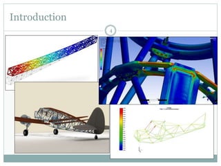


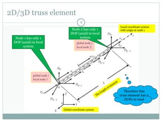


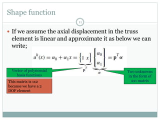


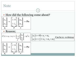


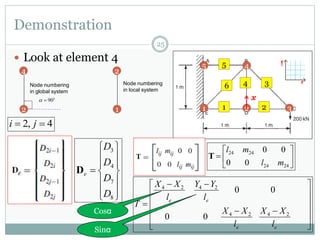

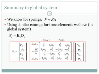


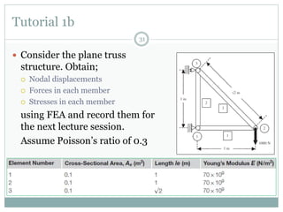


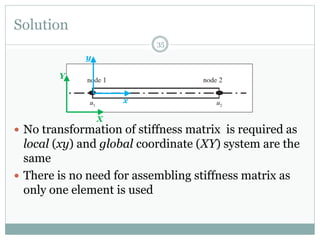


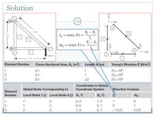

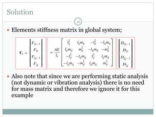

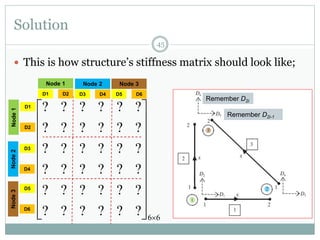
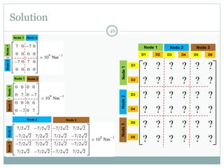
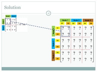

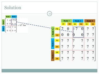


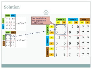

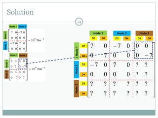


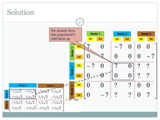


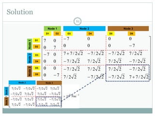
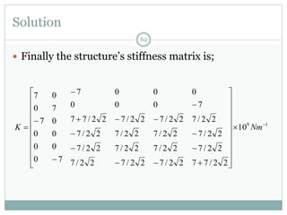

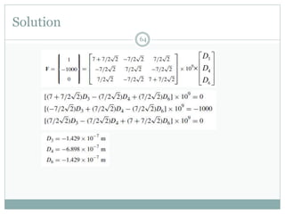
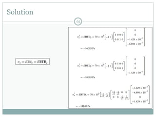

The document discusses the finite element method (FEM) for analyzing truss structures. It begins with objectives of becoming familiar with FEM concepts for truss elements like stiffness matrices and assembling the global stiffness matrix. It then covers derivation of the element stiffness matrix in local coordinates, transforming it to global coordinates, and assembling the global stiffness matrix of the overall structure from the element matrices. Strain and stress calculations are also briefly discussed. Finally, an example problem is presented to demonstrate the FEM process for a simple truss structure.