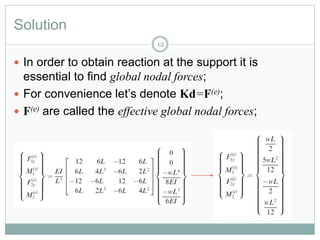
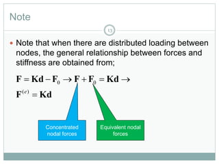
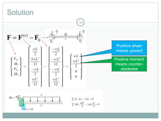
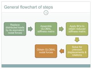
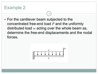
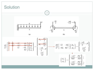
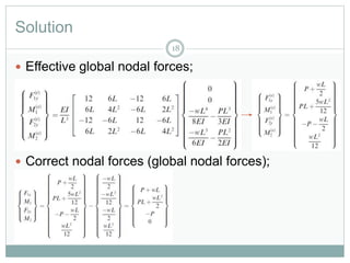
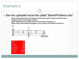
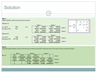
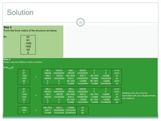
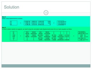
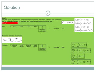
B Y
D R . M AH D I D AM G H AN I
2 0 1 7 - 2 0 1 8
Structural Design and Inspection-
Finite Element Method (Beams)
1
Suggested Readings
Reference 1 Reference 3
2
Reference 2
Objectives
3
 Familiarisation with equivalent nodal forces;
 Familiarisation with global nodal forces;
 Familiarisation with effective global nodal forces;
 Solving beam problems using Finite Element
Analysis having distributed loading between nodes.
Beam element
4
The length of element
Node 1 has only 2 DOF
(vertical displacement
and rotation)
Therefore, this
beam element has
4 DOFs in total
Node 2 has only 2 DOF
(vertical displacement
and rotation)
Local coordinate system with
origin at the middle of beam
This slide shows positive direction of
shear forces, bending moments,
displacements and rotations.
Example 1
5
 For the cantilever beam subjected to the uniform
load w, solve for the right-end vertical displacement
and rotation and then for the nodal forces. Assume
the beam to have constant EI throughout its length.
Solution
6
 We begin by discretizing the beam;
 Only one element will be used to represent the
whole beam;
 Next, the distributed load is replaced by its work-
equivalent nodal forces.
Note
7
 Equivalent nodal loading for a distributed loading can be
obtained by calculation of fixed end reactions as we saw in
slope deflection method;
 We have replaced the uniformly distributed load by a
statically equivalent force system consisting of a
concentrated nodal force and moment at each end of the
member carrying the distributed load;
 These statically equivalent forces are always of opposite
sign from the fixed-end reactions.
Note
8
 If we want to analyse the behaviour of loaded
member 2–3 in better detail, we can place a node at
mid-span;
 Use the same procedure just described for each of
the two elements representing the horizontal
member.
Note
9
Solution
10
 Local and global axis are coincident.
Reduced stiffness
matrix
Solution
11
 Negative sign for displacement means it is
downward;
 Negative sign for rotation means it is clockwise;
 Remind yourselves of positive sign conventions.
Solution
12
 In order to obtain reaction at the support it is
essential to find global nodal forces;
 For convenience let’s denote Kd=F(e);
 F(e) are called the effective global nodal forces;
Note
13
 Note that when there are distributed loading between
nodes, the general relationship between forces and
stiffness are obtained from;
KdF
KdFFFKdF


)(
00
e
Concentrated
nodal forces
Equivalent nodal
forces
Solution
14
0
)(
FFF  e
Positive shear
means upward
Positive moment
means counter-
clockwise
General flowchart of steps
15
Replace
distributed loads
by its equivalent
nodal forces
Assemble
GLOBAL
stiffness matrix
Apply BCs to
obtain reduced
stiffness matrix
Solve for
unknown
displacements &
rotations
Obtain GLOBAL
nodal forces
Example 2
16
 For the cantilever beam subjected to the
concentrated free-end load P and the uniformly
distributed load w acting over the whole beam as,
determine the free-end displacements and the nodal
forces.
Solution
17
P
wL


2
Solution
18
 Effective global nodal forces;
 Correct nodal forces (global nodal forces);
Example 3
19
 See the uploaded excel file called “BeamProblems.xlsx”
Solution
20
Solution
21
Solution
22
Solution
23
Solution
24

Lec10 finite element_beam_structures 2

  • 1.
    B Y D R. M AH D I D AM G H AN I 2 0 1 7 - 2 0 1 8 Structural Design and Inspection- Finite Element Method (Beams) 1
  • 2.
    Suggested Readings Reference 1Reference 3 2 Reference 2
  • 3.
    Objectives 3  Familiarisation withequivalent nodal forces;  Familiarisation with global nodal forces;  Familiarisation with effective global nodal forces;  Solving beam problems using Finite Element Analysis having distributed loading between nodes.
  • 4.
    Beam element 4 The lengthof element Node 1 has only 2 DOF (vertical displacement and rotation) Therefore, this beam element has 4 DOFs in total Node 2 has only 2 DOF (vertical displacement and rotation) Local coordinate system with origin at the middle of beam This slide shows positive direction of shear forces, bending moments, displacements and rotations.
  • 5.
    Example 1 5  Forthe cantilever beam subjected to the uniform load w, solve for the right-end vertical displacement and rotation and then for the nodal forces. Assume the beam to have constant EI throughout its length.
  • 6.
    Solution 6  We beginby discretizing the beam;  Only one element will be used to represent the whole beam;  Next, the distributed load is replaced by its work- equivalent nodal forces.
  • 7.
    Note 7  Equivalent nodalloading for a distributed loading can be obtained by calculation of fixed end reactions as we saw in slope deflection method;  We have replaced the uniformly distributed load by a statically equivalent force system consisting of a concentrated nodal force and moment at each end of the member carrying the distributed load;  These statically equivalent forces are always of opposite sign from the fixed-end reactions.
  • 8.
    Note 8  If wewant to analyse the behaviour of loaded member 2–3 in better detail, we can place a node at mid-span;  Use the same procedure just described for each of the two elements representing the horizontal member.
  • 9.
  • 10.
    Solution 10  Local andglobal axis are coincident. Reduced stiffness matrix
  • 11.
    Solution 11  Negative signfor displacement means it is downward;  Negative sign for rotation means it is clockwise;  Remind yourselves of positive sign conventions.
  • 12.
    Solution 12  In orderto obtain reaction at the support it is essential to find global nodal forces;  For convenience let’s denote Kd=F(e);  F(e) are called the effective global nodal forces;
  • 13.
    Note 13  Note thatwhen there are distributed loading between nodes, the general relationship between forces and stiffness are obtained from; KdF KdFFFKdF   )( 00 e Concentrated nodal forces Equivalent nodal forces
  • 14.
    Solution 14 0 )( FFF  e Positiveshear means upward Positive moment means counter- clockwise
  • 15.
    General flowchart ofsteps 15 Replace distributed loads by its equivalent nodal forces Assemble GLOBAL stiffness matrix Apply BCs to obtain reduced stiffness matrix Solve for unknown displacements & rotations Obtain GLOBAL nodal forces
  • 16.
    Example 2 16  Forthe cantilever beam subjected to the concentrated free-end load P and the uniformly distributed load w acting over the whole beam as, determine the free-end displacements and the nodal forces.
  • 17.
  • 18.
    Solution 18  Effective globalnodal forces;  Correct nodal forces (global nodal forces);
  • 19.
    Example 3 19  Seethe uploaded excel file called “BeamProblems.xlsx”
  • 20.
  • 21.
  • 22.
  • 23.
  • 24.