Downloaded 132 times

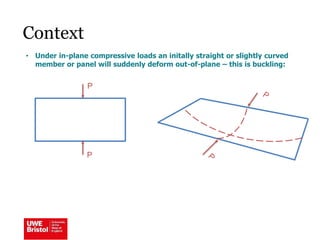
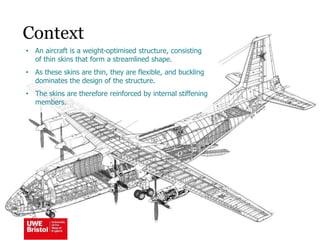
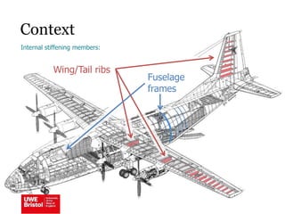
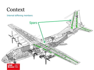
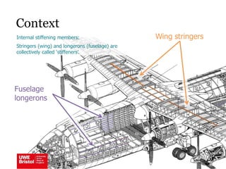
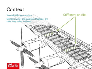
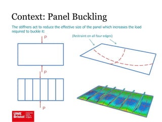
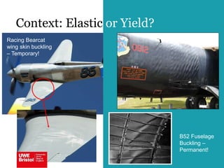

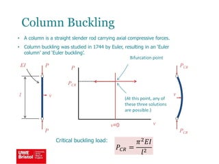
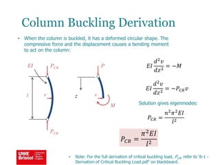
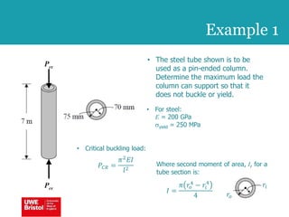
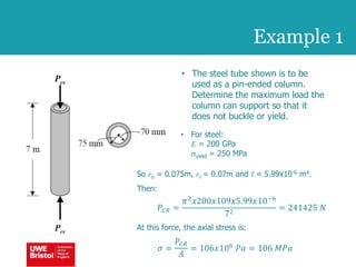
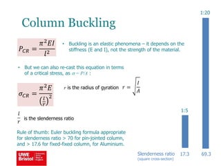
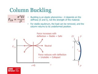
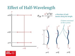
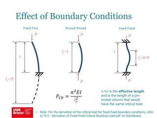
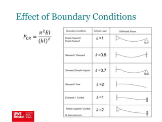
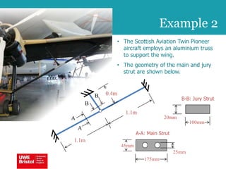
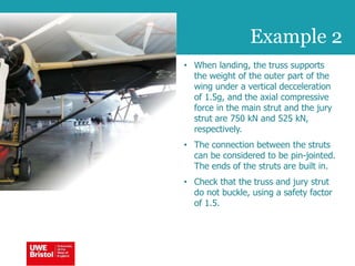
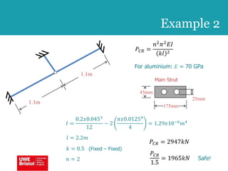
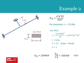
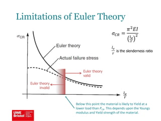
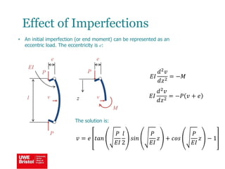
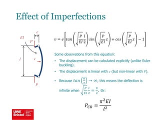
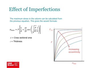
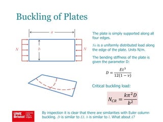
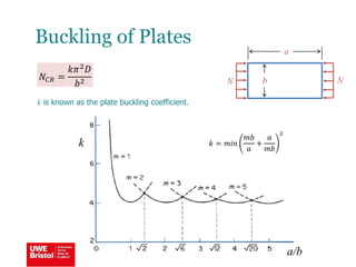
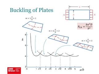


The document discusses aerostructures and the phenomenon of buckling, particularly focusing on wing spars and column buckling in aircraft design. It covers critical buckling loads, boundary conditions, and the role of internal stiffening members in increasing load capacity. Additionally, it explores similarities between column and plate buckling, offering examples and critical concepts for design safety and structural integrity.


