SlideShare a Scribd company logo
Element 4 Element 1 Element 2 Element 3
U2 U4
U1 Element 1 U3
Local dof for each element
Truss Example
In the figure above we want to use finite element method to compute the stresses
in a truss, we will develop the global stiffness matrix, Nodal Displacements, and
Reaction forces.
Computing Nodal Displacements
2q
1q 3q
8q
7q
6q
5q
4q
20,000lbs
25,000lbs
40''
30''
6
29.5*10E 
2
1.0Area in
There are 4 nodes and 4 elements making up the truss. We are going to do a two
dimensional analysis so each node is constrained to move in only the X or Y direction.
We call these directions of motion degrees of freedom or dof for short. There are 4
nodes and 8 degrees of freedom (two degrees of freedom for each node). We can
number the degrees of freedom with the formulas:
Vertical degree of freedom dof=2*node
Horizontal degree of freedom dof=2*node-1
Where node is the node number
We can locate each node by its coordinates. The table below shows the
coordinate of the nodes in the problem we are solving. We can use these coordinates to
determine the lengths and angles of the elements.
Each element can be described as extending from one node to another. This
also can be defined in a table below.
Element From
Node
To Node
1 1 2
2 3 2
3 1 3
4 4 3
From these two tables we can derive the lengths of each element and the cosine
and sine of their orientation. This is shown in the table below.
Element Length Cosine Sine
1 40 1 0
2 30 0 -1
3 50 0.8 0.6
4 40 1 0
Node X Y
1 0 0
2 40 0
3 40 30
4 0 30
In the formula below we can develop the stiffness matrix for an element.
2 2
2 2
2 2
2 2
. .
. .
. .
. .
Cos Cos Sin Cos Cos Sin
Cos Sin Sin Cos Sin SinAE
K
L Cos Cos Sin Cos Cos Sin
Cos Sin Sin Cos Sin Sin
     
     
     
     
  
 
  
  
 
  
This stiffness matrix is for an element. The element attaches to two nodes and
each of these nodes has two degrees of freedom. The rows and the columns of the
stiffness matrix correlate to those degrees of freedom.
Using the equation shown on top we can construct that stiffness matrix for
element 1 defined in the table above. The stiffness matrix is:
1 2 3 4
6
1
1 0 1 0 1
0 0 0 0 229.5*10
1 0 1 0 340
0 0 0 0 4
K
 
 
 
 
 
 
Element 2
6
2
0 0 0 0 5
0 1 0 1 629.5*10
0 0 0 0 330
0 1 0 1 4
K
 
  
 
 
 
Element 3
6
3
0.64 0.48 0.64 0.48 1
0.48 0.36 0.48 0.36 229.5*10
0.64 0.48 0.64 0.48 550
0.48 0.36 0.48 0.36 6
K
  
   
 
 
  
Element 4
6
4
1 0 1 0 7
0 0 0 0 829.5*10
1 0 1 0 540
0 0 0 0 6
K
 
 
 
 
 
 
The next step is to add the stiffness matrices for the element to create a matrix
for the entire structure. We can facilitate this by creating a common factor for Young’s
modulus and the length of the elements.
For element 1, we divide the outside by 15 and multiply each element of the
matrix by 15. Multiplying and dividing by the same number is the same as multiplying
and dividing by 1.
6
1
15 0 15 0 1
0 0 0 0 229.5*10
15 0 15 0 3600
0 0 0 0 4
K
 
 
 
 
 
 
Multiply and divide element 2 by 20.
6
2
0 0 0 0 5
0 20 0 20 629.5*10
0 0 0 0 3600
0 20 0 20 4
K
 
  
 
 
 
Multiply and divide element 3 by 12.
6
3
7.68 5.76 7.68 5.76 1
5.76 4.32 5.76 4.32 229.5*10
7.68 5.76 7.68 5.76 5600
5.76 4.32 5.76 4.32 6
K
  
   
 
 
  
We do the same for element 4 by multiplying and dividing it by 15.
6
4
15 0 15 0 7
0 0 0 0 829.5*10
15 0 15 0 5600
0 0 0 0 6
K
 
 
 
 
 
 
The coefficient for each stiffness matrix is the same so we can easily add the
matrices. We add the degree of freedom for each element stiffness matrix into the same
degree of freedom in the structural matrix. The resulting structural stiffness matrix is
shown below.
6
1 2 3 4 5 6 7 8
22.68 5.76 15.0 0 7.68 5.76 0 0 1
5.76 4.32 0 0 5.76 4.32 0 0 2
15.0 0 15.0 0 0 0 0 0 3
29.5*10
0 0 0 20.0 0 20.0 0 0 4
600
7.68 5.76 0 0 22.68 5.76 15.0 0 5
5.76 4.32 0 20.0 5.76 24.32 0 0 6
0 0 0 0 15.0 0 15.0 0 7
0 0 0 0 0 0 0 0 8
K
 
   
  


 

  
 



 












Now remembering the basic equation
*K Q F
Where K is the structural stiffness matrix, Q is the displacement of each node, and F is
the external force matrix. This result in equation below by substituting
1
2
36
22.68 5.76 15.0 0 7.68 5.76 0 0
5.76 4.32 0 0 5.76 4.32 0 0
15.0 0 15.0 0 0 0 0 0
29.5*10
0 0 0 20.0 0 20.0 0 0
600
7.68 5.76 0 0 22.68 5.76 15.0 0
5.76 4.32 0 20.0 5.76 24.32 0 0
0 0 0 0 15.0 0 15.0 0
0 0 0 0 0 0 0 0
q
q
q
 
    
  
 
 
 
 
   
  
 
 
 
 
4
5
6
7
8
0
0
20,000
0
0
25,000
0
0
q
q
q
q
q
   
   
   
   
   
   
   
   
   
   
   
   
   
    
We have boundary conditions at the fixed supports. Our assumption is that these
joints will not move in the constrained displacements are dof 1, 2, 4, 7, and 8. The
resulting matrix is:
36
5
4
15 0 0 20,000
29.5*10
0 22.68 5.76 0
600
0 5.76 24.32 25,000
q
q
q
     
         
          
We can use Gaussian elimination or any number of other solution techniques to
solve the system of equations shown above. Doing so yields
3
3
3
5
3
4
27.12*10
5.65*10
22.25*10
q
q inches
q



  
  
   
      
Computing stresses
We can find the stresses by the formula below
 
E
Cos Sin Cos Sin q
L
      
We use this equation to compute the stress in each element.
 
6
1 3
0 1
0 229.5*10
1 0 1 0
27.12*10 340
0 4
 
 
 
 
   
 
  
Or
1 20,000psi 
 
3
36
2 1
55.65*10
622.25*1029.5*10
0 1 0 1
330 27.12*10
40




 
 
 
   
 
  
Or
2 21,880psi 
By using the similar technique we get
3 5,208psi 
And
4 4,167psi 
Computing the reactions
The last step is to compute the support reactions. We need to determine the
reaction forces along dof 1, 2, 3, 7, and 8 which correspond to the fixed supports. These
are obtained by substituting Q into the original finite element equation.
R KQ F 
We only need to use those rows of the structural stiffness matrix that correspond
to the fixed supports. At these supports, we are not supplying an external force so F=0.
Our equation becomes
R KQ
Or
1 3
2 6
4 3
7 3
8
0
0
22.68 5.76 15.0 0 7.68 5.76 0 0
27.12*10
5.76 4.32 0 0 5.76 4.32 0 0
029.5*10
0 0 0 20 0 20 0 0
5.65*10600
0 0 0 0 15.0 0 15.0 0
22.25*10
0 0 0 0 0 0 0 0
0
0
R
R
R
R
R



 
 
      
              
     
    
    
      


 


We multiply the stiffness matrix K and the deformation vector Q to get the
reactions.
They are shown in the following equation.
1
2
4
7
8
15,8333
3,126
21,879
4,167
0
R
R
R
R
R
   
   
      
   
   
   
     

More Related Content

What's hot

Torsion of thin closed sections
Torsion of thin closed sectionsTorsion of thin closed sections
Torsion of thin closed sections
aero103
 
Soil Strength 2009
Soil Strength   2009Soil Strength   2009
Soil Strength 2009
dcwotring
 
FACTORS AFFECTING GREEN CONSTRUCTION PROJECT MANAGEMENT
FACTORS AFFECTING GREEN CONSTRUCTION PROJECT MANAGEMENTFACTORS AFFECTING GREEN CONSTRUCTION PROJECT MANAGEMENT
FACTORS AFFECTING GREEN CONSTRUCTION PROJECT MANAGEMENT
IAEME Publication
 
Stresses in a long cylindrical pressure vessel ansys lab v 12 30 2014
Stresses in a long cylindrical pressure vessel   ansys   lab v  12 30 2014Stresses in a long cylindrical pressure vessel   ansys   lab v  12 30 2014
Stresses in a long cylindrical pressure vessel ansys lab v 12 30 2014
Charlton Inao
 

What's hot (20)

Flow test of concrete
Flow test of concreteFlow test of concrete
Flow test of concrete
 
STUDY ON BEHAVIOUR OF PARTIAL REPLACEMENT OF CEMENT WITH SUGARCANE BAGASSE AS...
STUDY ON BEHAVIOUR OF PARTIAL REPLACEMENT OF CEMENT WITH SUGARCANE BAGASSE AS...STUDY ON BEHAVIOUR OF PARTIAL REPLACEMENT OF CEMENT WITH SUGARCANE BAGASSE AS...
STUDY ON BEHAVIOUR OF PARTIAL REPLACEMENT OF CEMENT WITH SUGARCANE BAGASSE AS...
 
Torsion of thin closed sections
Torsion of thin closed sectionsTorsion of thin closed sections
Torsion of thin closed sections
 
Midas gen advanced tutorial
Midas gen advanced tutorialMidas gen advanced tutorial
Midas gen advanced tutorial
 
0610 s16 qp_22
0610 s16 qp_220610 s16 qp_22
0610 s16 qp_22
 
Bs 1881 125 1986
Bs 1881 125 1986Bs 1881 125 1986
Bs 1881 125 1986
 
Soil Strength 2009
Soil Strength   2009Soil Strength   2009
Soil Strength 2009
 
FACTORS AFFECTING GREEN CONSTRUCTION PROJECT MANAGEMENT
FACTORS AFFECTING GREEN CONSTRUCTION PROJECT MANAGEMENTFACTORS AFFECTING GREEN CONSTRUCTION PROJECT MANAGEMENT
FACTORS AFFECTING GREEN CONSTRUCTION PROJECT MANAGEMENT
 
L20
L20L20
L20
 
Fem in geotech engineering
Fem in geotech engineeringFem in geotech engineering
Fem in geotech engineering
 
Yield line theory
Yield line theoryYield line theory
Yield line theory
 
Mathcad anchors (2)
Mathcad   anchors (2)Mathcad   anchors (2)
Mathcad anchors (2)
 
Module 7.pdf
Module 7.pdfModule 7.pdf
Module 7.pdf
 
Unconfined compression test
Unconfined compression testUnconfined compression test
Unconfined compression test
 
Proctor compaction test
Proctor compaction testProctor compaction test
Proctor compaction test
 
Atterberg Limits Test
Atterberg Limits TestAtterberg Limits Test
Atterberg Limits Test
 
Ce1302 design of rc elements
Ce1302 design of rc elementsCe1302 design of rc elements
Ce1302 design of rc elements
 
Presentation Moment Distribution Method
Presentation Moment Distribution MethodPresentation Moment Distribution Method
Presentation Moment Distribution Method
 
Stresses in a long cylindrical pressure vessel ansys lab v 12 30 2014
Stresses in a long cylindrical pressure vessel   ansys   lab v  12 30 2014Stresses in a long cylindrical pressure vessel   ansys   lab v  12 30 2014
Stresses in a long cylindrical pressure vessel ansys lab v 12 30 2014
 
Test for direct compressive strength of cement mortar, cylindrical concrete c...
Test for direct compressive strength of cement mortar, cylindrical concrete c...Test for direct compressive strength of cement mortar, cylindrical concrete c...
Test for direct compressive strength of cement mortar, cylindrical concrete c...
 

Similar to solution for 2D truss1

Lecture 3.pdf
Lecture 3.pdfLecture 3.pdf
Lecture 3.pdf
Yesuf3
 
Lecture 4.pdf
Lecture 4.pdfLecture 4.pdf
Lecture 4.pdf
Yesuf3
 
Lecture 2.pdf
Lecture 2.pdfLecture 2.pdf
Lecture 2.pdf
Yesuf3
 
ME 5720 Fall 2015 - Wind Turbine Project_FINAL
ME 5720 Fall 2015 - Wind Turbine Project_FINALME 5720 Fall 2015 - Wind Turbine Project_FINAL
ME 5720 Fall 2015 - Wind Turbine Project_FINAL
Omar Latifi
 

Similar to solution for 2D truss1 (20)

Lecture 3.pdf
Lecture 3.pdfLecture 3.pdf
Lecture 3.pdf
 
Lecture 4.pdf
Lecture 4.pdfLecture 4.pdf
Lecture 4.pdf
 
Lecture 2.pdf
Lecture 2.pdfLecture 2.pdf
Lecture 2.pdf
 
Chapter 08 2
Chapter 08 2Chapter 08 2
Chapter 08 2
 
Lecture 5.pdf
Lecture 5.pdfLecture 5.pdf
Lecture 5.pdf
 
Modeling of the damped oscillations of the viscous
Modeling of the damped oscillations of the viscousModeling of the damped oscillations of the viscous
Modeling of the damped oscillations of the viscous
 
Unit 1 notes-final
Unit 1 notes-finalUnit 1 notes-final
Unit 1 notes-final
 
Bazzucchi-Campolmi-Zatti
Bazzucchi-Campolmi-ZattiBazzucchi-Campolmi-Zatti
Bazzucchi-Campolmi-Zatti
 
Presentation on application of numerical method in our life
Presentation on application of numerical method in our lifePresentation on application of numerical method in our life
Presentation on application of numerical method in our life
 
Kakuro: Solving the Constraint Satisfaction Problem
Kakuro: Solving the Constraint Satisfaction ProblemKakuro: Solving the Constraint Satisfaction Problem
Kakuro: Solving the Constraint Satisfaction Problem
 
FEA_project1
FEA_project1FEA_project1
FEA_project1
 
Higher order elements
Higher order elementsHigher order elements
Higher order elements
 
s1233587_Report
s1233587_Reports1233587_Report
s1233587_Report
 
Modeling of the damped oscillations of the viscous beams structures with swiv...
Modeling of the damped oscillations of the viscous beams structures with swiv...Modeling of the damped oscillations of the viscous beams structures with swiv...
Modeling of the damped oscillations of the viscous beams structures with swiv...
 
Numerical Methods: Solution of system of equations
Numerical Methods: Solution of system of equationsNumerical Methods: Solution of system of equations
Numerical Methods: Solution of system of equations
 
applications of second order differential equations
applications of second order differential equationsapplications of second order differential equations
applications of second order differential equations
 
Cme434 project
Cme434 projectCme434 project
Cme434 project
 
ME 5720 Fall 2015 - Wind Turbine Project_FINAL
ME 5720 Fall 2015 - Wind Turbine Project_FINALME 5720 Fall 2015 - Wind Turbine Project_FINAL
ME 5720 Fall 2015 - Wind Turbine Project_FINAL
 
Study of a Gear-Rack and links System: Equations, configuration and CAD design
Study of a Gear-Rack and links System: Equations, configuration and CAD designStudy of a Gear-Rack and links System: Equations, configuration and CAD design
Study of a Gear-Rack and links System: Equations, configuration and CAD design
 
Torque Arm Modeling, Simulation & Optimization using Finite Element Methods
Torque Arm Modeling, Simulation & Optimization using Finite Element MethodsTorque Arm Modeling, Simulation & Optimization using Finite Element Methods
Torque Arm Modeling, Simulation & Optimization using Finite Element Methods
 

solution for 2D truss1

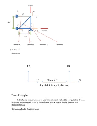
  • 1. Element 4 Element 1 Element 2 Element 3 U2 U4 U1 Element 1 U3 Local dof for each element Truss Example In the figure above we want to use finite element method to compute the stresses in a truss, we will develop the global stiffness matrix, Nodal Displacements, and Reaction forces. Computing Nodal Displacements 2q 1q 3q 8q 7q 6q 5q 4q 20,000lbs 25,000lbs 40'' 30'' 6 29.5*10E  2 1.0Area in
  • 2. There are 4 nodes and 4 elements making up the truss. We are going to do a two dimensional analysis so each node is constrained to move in only the X or Y direction. We call these directions of motion degrees of freedom or dof for short. There are 4 nodes and 8 degrees of freedom (two degrees of freedom for each node). We can number the degrees of freedom with the formulas: Vertical degree of freedom dof=2*node Horizontal degree of freedom dof=2*node-1 Where node is the node number We can locate each node by its coordinates. The table below shows the coordinate of the nodes in the problem we are solving. We can use these coordinates to determine the lengths and angles of the elements. Each element can be described as extending from one node to another. This also can be defined in a table below. Element From Node To Node 1 1 2 2 3 2 3 1 3 4 4 3 From these two tables we can derive the lengths of each element and the cosine and sine of their orientation. This is shown in the table below. Element Length Cosine Sine 1 40 1 0 2 30 0 -1 3 50 0.8 0.6 4 40 1 0 Node X Y 1 0 0 2 40 0 3 40 30 4 0 30
  • 3. In the formula below we can develop the stiffness matrix for an element. 2 2 2 2 2 2 2 2 . . . . . . . . Cos Cos Sin Cos Cos Sin Cos Sin Sin Cos Sin SinAE K L Cos Cos Sin Cos Cos Sin Cos Sin Sin Cos Sin Sin                                         This stiffness matrix is for an element. The element attaches to two nodes and each of these nodes has two degrees of freedom. The rows and the columns of the stiffness matrix correlate to those degrees of freedom. Using the equation shown on top we can construct that stiffness matrix for element 1 defined in the table above. The stiffness matrix is: 1 2 3 4 6 1 1 0 1 0 1 0 0 0 0 229.5*10 1 0 1 0 340 0 0 0 0 4 K             Element 2 6 2 0 0 0 0 5 0 1 0 1 629.5*10 0 0 0 0 330 0 1 0 1 4 K            Element 3 6 3 0.64 0.48 0.64 0.48 1 0.48 0.36 0.48 0.36 229.5*10 0.64 0.48 0.64 0.48 550 0.48 0.36 0.48 0.36 6 K              
  • 4. Element 4 6 4 1 0 1 0 7 0 0 0 0 829.5*10 1 0 1 0 540 0 0 0 0 6 K             The next step is to add the stiffness matrices for the element to create a matrix for the entire structure. We can facilitate this by creating a common factor for Young’s modulus and the length of the elements. For element 1, we divide the outside by 15 and multiply each element of the matrix by 15. Multiplying and dividing by the same number is the same as multiplying and dividing by 1. 6 1 15 0 15 0 1 0 0 0 0 229.5*10 15 0 15 0 3600 0 0 0 0 4 K             Multiply and divide element 2 by 20. 6 2 0 0 0 0 5 0 20 0 20 629.5*10 0 0 0 0 3600 0 20 0 20 4 K            Multiply and divide element 3 by 12. 6 3 7.68 5.76 7.68 5.76 1 5.76 4.32 5.76 4.32 229.5*10 7.68 5.76 7.68 5.76 5600 5.76 4.32 5.76 4.32 6 K              
  • 5. We do the same for element 4 by multiplying and dividing it by 15. 6 4 15 0 15 0 7 0 0 0 0 829.5*10 15 0 15 0 5600 0 0 0 0 6 K             The coefficient for each stiffness matrix is the same so we can easily add the matrices. We add the degree of freedom for each element stiffness matrix into the same degree of freedom in the structural matrix. The resulting structural stiffness matrix is shown below. 6 1 2 3 4 5 6 7 8 22.68 5.76 15.0 0 7.68 5.76 0 0 1 5.76 4.32 0 0 5.76 4.32 0 0 2 15.0 0 15.0 0 0 0 0 0 3 29.5*10 0 0 0 20.0 0 20.0 0 0 4 600 7.68 5.76 0 0 22.68 5.76 15.0 0 5 5.76 4.32 0 20.0 5.76 24.32 0 0 6 0 0 0 0 15.0 0 15.0 0 7 0 0 0 0 0 0 0 0 8 K                                     Now remembering the basic equation *K Q F Where K is the structural stiffness matrix, Q is the displacement of each node, and F is the external force matrix. This result in equation below by substituting
  • 6. 1 2 36 22.68 5.76 15.0 0 7.68 5.76 0 0 5.76 4.32 0 0 5.76 4.32 0 0 15.0 0 15.0 0 0 0 0 0 29.5*10 0 0 0 20.0 0 20.0 0 0 600 7.68 5.76 0 0 22.68 5.76 15.0 0 5.76 4.32 0 20.0 5.76 24.32 0 0 0 0 0 0 15.0 0 15.0 0 0 0 0 0 0 0 0 0 q q q                                  4 5 6 7 8 0 0 20,000 0 0 25,000 0 0 q q q q q                                                          We have boundary conditions at the fixed supports. Our assumption is that these joints will not move in the constrained displacements are dof 1, 2, 4, 7, and 8. The resulting matrix is: 36 5 4 15 0 0 20,000 29.5*10 0 22.68 5.76 0 600 0 5.76 24.32 25,000 q q q                            We can use Gaussian elimination or any number of other solution techniques to solve the system of equations shown above. Doing so yields 3 3 3 5 3 4 27.12*10 5.65*10 22.25*10 q q inches q                     Computing stresses We can find the stresses by the formula below   E Cos Sin Cos Sin q L        We use this equation to compute the stress in each element.
  • 7.   6 1 3 0 1 0 229.5*10 1 0 1 0 27.12*10 340 0 4                  Or 1 20,000psi    3 36 2 1 55.65*10 622.25*1029.5*10 0 1 0 1 330 27.12*10 40                    Or 2 21,880psi  By using the similar technique we get 3 5,208psi  And 4 4,167psi 
  • 8. Computing the reactions The last step is to compute the support reactions. We need to determine the reaction forces along dof 1, 2, 3, 7, and 8 which correspond to the fixed supports. These are obtained by substituting Q into the original finite element equation. R KQ F  We only need to use those rows of the structural stiffness matrix that correspond to the fixed supports. At these supports, we are not supplying an external force so F=0. Our equation becomes R KQ Or 1 3 2 6 4 3 7 3 8 0 0 22.68 5.76 15.0 0 7.68 5.76 0 0 27.12*10 5.76 4.32 0 0 5.76 4.32 0 0 029.5*10 0 0 0 20 0 20 0 0 5.65*10600 0 0 0 0 15.0 0 15.0 0 22.25*10 0 0 0 0 0 0 0 0 0 0 R R R R R                                                           We multiply the stiffness matrix K and the deformation vector Q to get the reactions. They are shown in the following equation. 1 2 4 7 8 15,8333 3,126 21,879 4,167 0 R R R R R                                 