Downloaded 139 times

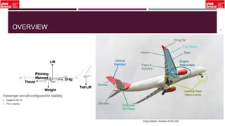
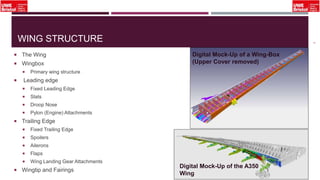


The document outlines an overview of structural idealisation in aircraft design, focusing on the simplification of complex wing structures for stress analysis. It highlights the components of wing structures, their load-carrying mechanisms, and the importance of idealisation for accurate stress distribution analysis. Additionally, it categorizes structural components based on their criticality to aircraft safety and discusses methods for modeling these structures using finite element analysis.


