Downloaded 173 times

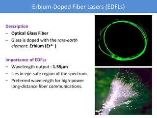
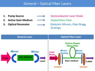
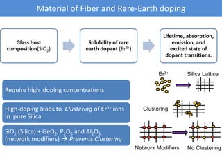
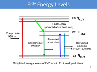
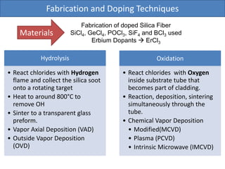
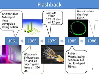
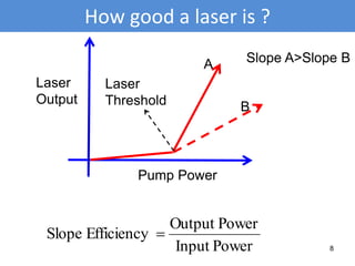
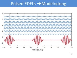
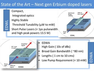
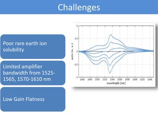
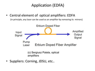

The document discusses erbium-doped fiber lasers (EDFLs). EDFLs emit light at 1.55μm, which lies in the eye-safe region of the spectrum and is preferred for long-distance fiber optic communications. They consist of an optical fiber doped with erbium ions as the gain medium, pump lasers to excite the erbium ions, and dielectric mirrors or fiber Bragg gratings to form the optical resonator. EDFLs have revolutionized fiber optic communications and next generation versions may be integrated onto single chips.


