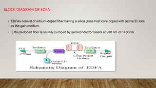
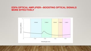
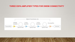
SEMINAR TOPIC
ON
EDFAS: ARCHITECTURE ,WORKING & TYPES
PRESENTED TO: PRESENTED BY :
DR. BC CHOUDHARY SACHIN MAITHANI
DR. BALWINDER RAJ M.E.(REGULAR)
(ECE)
TABLE OF CONTENT
• 1. Introduction
• 2. Block diagram of EDFA
• 3. Why Erbium?
• 4. Amplification Mechanism
• 5. LOSS-GA IN Characteristics
• 6. Maximum possible gain
• 7. Input- Output Characteristics
• 8. 980 nm vs 1 440 nm pumping EDFAs
• 9.How does an EDFAs Work?
• 10. Types of EDFAs
• 11. EDFA Optical Amplifier—Boosting Optical Signals More Effectively
• 12. Three EDFAAmplifier Types for DWDM Connectivity
• 13. Advantages OF EDFA
• 14. Drawbacks of EDFAs
• 15. Applications of EDFA
• 16. .Summary
• 17.Refrences
INTRODUCTION
BLOCK DIAGRAM OF EDFA
• EDFAs consist of erbium-doped fiber having a silica glass host core doped with active Er ions
as the gain medium.
• Erbium-doped fiber is usually pumped by semiconductor lasers at 980 nm or 1480nm
WHY ERBIUM?
• Erbium has several important properties that make it an excellent choice for an optical
amplifier
• Erbium ions (Er3+) have quantum levels that allows them to be stimulated to emit in the
1550 nm band, which is the band that has the least power loss in most silica-based fiber.
• Erbium's quantum levels also allow it to be excited by a signal at either 980nm or1480nm,
both of which silica-based fiber can carry without great losses
AMPLIFICATION MECHANISM
Step 1: The possible pump wavelengths are 980 & 1
480 nm In normal operation ,a pump
laseremitting980-nm photons is used to excite ions from the ground state to the pump level,
as shown by transition process.
Step 2: Duringthis decay , the excess energy is released as phonons or, equivalently,
mechanical vibrations in the fiber Within the metastable band , the electrons of the excited
ions tend to populate the lower end of the band.
AMPLIFICATION MECHANISM
Step 3: Another possible pump wavelength is 1480 nm. The energy of these pump photons is
very similar to the signal-photon energy , but s lightly higher .
Step 4: Some of the ions sitting at the metastable level can decay back to the ground state in
the absence of an externally stimulating photon flux, as shown by transition process. This-
decay phenomenon is known as spontaneous emission and adds to the amplifier noise.
AMPLIFICATION MECHANISM
• Step 5 & 6: Two more types of transitions occur when a flux of signal photons that have
energies corresponding to the band gap energy between the ground state and the
metastable level passes through the device. First, a small portion of the external photons
will be absorbed by ions in the ground state
• Step 7: stimulated emission process a signal photon triggers an excited ion to drop to
the ground state , thereby emitting new photon of the same energy , wavevector and
polarization as the incoming signal photon.
LOSS-GAINCHARACTERISTICS
MAXIMUM POSSIBLE GAIN
INPUT- OUTPUT CHARACTERISTICS
980 NM VS 1480 NM PUMPING EDFA
HOW DOES AN EDFA WORK?
• The basic structure of an EDFA consists of a length of Erbium-doped fiber (EDF), a pump
laser, and a WDM combiner.
• The WDM combiner is for combining the signal and pump wavelength so that they can
propagate simultaneously through the EDF.
• The optical signal, such as a 1550nm signal, enters an EDFA amplifier from the input. The
1550nm signal is combined with a 980nm pump laser with a WDM device.
• The signal and the pump laser pass through a length of fiber doped with Erbium ions.
• As we talked above, EDFA uses the erbium-doped fiber as an optical amplification
medium. The 1550nm signal is amplified through interaction with the doping Erbium ions.
• This action amplifies a weak optical signal to a higher power, effecting a boost in the signal
strength.
EDFA TYPES:
• EDFA amplifiers are of three types based on their purpose:
• Optical Boost Amplifier (OBA)
• Optical Pre Amplifier (OPA)
• Optical Line Amplifier (OLA)
OPTICAL BOOST AMPLIFIER (OBA)
• The optical boost amplifier is placed just after the transmitter. It amplifies the multiplexed
optical signals before sending into optical fiber.
• Features of OBA
• High input power
• High output power
• Medium optical gain
OPTICAL PRE AMPLIFIER (OPA)
• The optical pre-amplifier is placed just before the receiver, such that sufficient optical
power will be received by the receiver. OPA is designed for optical amplification to
compensate for losses in a de-multiplexer located near the receiver.
• Features of OPA
• Medium to low input power
• Medium output power
• Medium optical gain
OPTICAL LINE AMPLIFIER (OLA) OR IN-LINE AMPLIFIER
• The optical line amplifier is placed in the middle of the transmission line. It compensates the
optical signal loss caused by the optical fiber. The typical distance between each of the OLA
is 40 km, 60km, 80km, or 100km, depends on the requirement. OLA is designed for optical
amplification between two network nodes on the main optical link.
• Features of OLA
• Medium to low input power
• High output power
• High optical gain
EDFA OPTICAL AMPLIFIER—BOOSTING OPTICAL SIGNALS
MORE EFFECTIVELY
THREE EDFA AMPLIFIER TYPES FOR DWDM CONNECTIVITY
ADVANTAGES OF EDFA
• EDFA has high pump power utilization (>50%).
• EDFA directly and simultaneously amplifies a wide wavelength band (>80nm) in the
1550nm region, with a relatively flat gain.
• Flatness can be improved by gain-flattening optical filters.
• Gain in excess of 50 db.
• EDFA features low noise figure suitable for long haul applications.
• EDFA deployment is relatively easier to realize and more affordable compared with
other signal amplification methods.
DRAWBACKS OF EDFA
• The size of EDFA amplifier is not small.
• Unlike SOA and Ramen amplifier, EDFA, with a typical size of ten meters long, is difficult
to integrate with other semiconductor devices.
• Since dropping channels can give rise to errors in surviving channels, dynamic control of
amplifiers is necessary.
APPLICATIONS OF EDFA
• Dense Wavelength Division Multiplexing (DWDM)
.
SUMMARY
• As EDFA performs as the most widely used optical amplifier, EDFA technology proves to
be the most advanced one that holds the dominant position in the market.
• With the deployment of WDM systems and the increasing aggregate bandwidth of
optical fibers, WDM system integrated with EDFA will gain more benefits.
REFERENCES
• 1.Wikipedia
• 2. https://ieeexplore.ieee.org/document/9105942
• 3. https://www.physics-and-radio-electronics.com/blog/edfa-erbium-doped-fiber-
amplifier/
EDFA amplifier ppt

EDFA amplifier ppt

  • 1.
    SEMINAR TOPIC ON EDFAS: ARCHITECTURE,WORKING & TYPES PRESENTED TO: PRESENTED BY : DR. BC CHOUDHARY SACHIN MAITHANI DR. BALWINDER RAJ M.E.(REGULAR) (ECE)
  • 2.
    TABLE OF CONTENT •1. Introduction • 2. Block diagram of EDFA • 3. Why Erbium? • 4. Amplification Mechanism • 5. LOSS-GA IN Characteristics • 6. Maximum possible gain • 7. Input- Output Characteristics • 8. 980 nm vs 1 440 nm pumping EDFAs • 9.How does an EDFAs Work? • 10. Types of EDFAs • 11. EDFA Optical Amplifier—Boosting Optical Signals More Effectively • 12. Three EDFAAmplifier Types for DWDM Connectivity • 13. Advantages OF EDFA • 14. Drawbacks of EDFAs • 15. Applications of EDFA • 16. .Summary • 17.Refrences
  • 3.
  • 4.
    BLOCK DIAGRAM OFEDFA • EDFAs consist of erbium-doped fiber having a silica glass host core doped with active Er ions as the gain medium. • Erbium-doped fiber is usually pumped by semiconductor lasers at 980 nm or 1480nm
  • 5.
    WHY ERBIUM? • Erbiumhas several important properties that make it an excellent choice for an optical amplifier • Erbium ions (Er3+) have quantum levels that allows them to be stimulated to emit in the 1550 nm band, which is the band that has the least power loss in most silica-based fiber. • Erbium's quantum levels also allow it to be excited by a signal at either 980nm or1480nm, both of which silica-based fiber can carry without great losses
  • 6.
  • 7.
    AMPLIFICATION MECHANISM Step 1:The possible pump wavelengths are 980 & 1 480 nm In normal operation ,a pump laseremitting980-nm photons is used to excite ions from the ground state to the pump level, as shown by transition process. Step 2: Duringthis decay , the excess energy is released as phonons or, equivalently, mechanical vibrations in the fiber Within the metastable band , the electrons of the excited ions tend to populate the lower end of the band.
  • 8.
    AMPLIFICATION MECHANISM Step 3:Another possible pump wavelength is 1480 nm. The energy of these pump photons is very similar to the signal-photon energy , but s lightly higher . Step 4: Some of the ions sitting at the metastable level can decay back to the ground state in the absence of an externally stimulating photon flux, as shown by transition process. This- decay phenomenon is known as spontaneous emission and adds to the amplifier noise.
  • 9.
    AMPLIFICATION MECHANISM • Step5 & 6: Two more types of transitions occur when a flux of signal photons that have energies corresponding to the band gap energy between the ground state and the metastable level passes through the device. First, a small portion of the external photons will be absorbed by ions in the ground state • Step 7: stimulated emission process a signal photon triggers an excited ion to drop to the ground state , thereby emitting new photon of the same energy , wavevector and polarization as the incoming signal photon.
  • 10.
  • 11.
  • 12.
  • 13.
    980 NM VS1480 NM PUMPING EDFA
  • 14.
    HOW DOES ANEDFA WORK?
  • 15.
    HOW DOES ANEDFA WORK? • The basic structure of an EDFA consists of a length of Erbium-doped fiber (EDF), a pump laser, and a WDM combiner. • The WDM combiner is for combining the signal and pump wavelength so that they can propagate simultaneously through the EDF. • The optical signal, such as a 1550nm signal, enters an EDFA amplifier from the input. The 1550nm signal is combined with a 980nm pump laser with a WDM device. • The signal and the pump laser pass through a length of fiber doped with Erbium ions. • As we talked above, EDFA uses the erbium-doped fiber as an optical amplification medium. The 1550nm signal is amplified through interaction with the doping Erbium ions. • This action amplifies a weak optical signal to a higher power, effecting a boost in the signal strength.
  • 16.
    EDFA TYPES: • EDFAamplifiers are of three types based on their purpose: • Optical Boost Amplifier (OBA) • Optical Pre Amplifier (OPA) • Optical Line Amplifier (OLA)
  • 17.
    OPTICAL BOOST AMPLIFIER(OBA) • The optical boost amplifier is placed just after the transmitter. It amplifies the multiplexed optical signals before sending into optical fiber. • Features of OBA • High input power • High output power • Medium optical gain
  • 18.
    OPTICAL PRE AMPLIFIER(OPA) • The optical pre-amplifier is placed just before the receiver, such that sufficient optical power will be received by the receiver. OPA is designed for optical amplification to compensate for losses in a de-multiplexer located near the receiver. • Features of OPA • Medium to low input power • Medium output power • Medium optical gain
  • 19.
    OPTICAL LINE AMPLIFIER(OLA) OR IN-LINE AMPLIFIER • The optical line amplifier is placed in the middle of the transmission line. It compensates the optical signal loss caused by the optical fiber. The typical distance between each of the OLA is 40 km, 60km, 80km, or 100km, depends on the requirement. OLA is designed for optical amplification between two network nodes on the main optical link. • Features of OLA • Medium to low input power • High output power • High optical gain
  • 20.
    EDFA OPTICAL AMPLIFIER—BOOSTINGOPTICAL SIGNALS MORE EFFECTIVELY
  • 21.
    THREE EDFA AMPLIFIERTYPES FOR DWDM CONNECTIVITY
  • 22.
    ADVANTAGES OF EDFA •EDFA has high pump power utilization (>50%). • EDFA directly and simultaneously amplifies a wide wavelength band (>80nm) in the 1550nm region, with a relatively flat gain. • Flatness can be improved by gain-flattening optical filters. • Gain in excess of 50 db. • EDFA features low noise figure suitable for long haul applications. • EDFA deployment is relatively easier to realize and more affordable compared with other signal amplification methods.
  • 23.
    DRAWBACKS OF EDFA •The size of EDFA amplifier is not small. • Unlike SOA and Ramen amplifier, EDFA, with a typical size of ten meters long, is difficult to integrate with other semiconductor devices. • Since dropping channels can give rise to errors in surviving channels, dynamic control of amplifiers is necessary.
  • 24.
    APPLICATIONS OF EDFA •Dense Wavelength Division Multiplexing (DWDM)
  • 25.
    . SUMMARY • As EDFAperforms as the most widely used optical amplifier, EDFA technology proves to be the most advanced one that holds the dominant position in the market. • With the deployment of WDM systems and the increasing aggregate bandwidth of optical fibers, WDM system integrated with EDFA will gain more benefits.
  • 26.
    REFERENCES • 1.Wikipedia • 2.https://ieeexplore.ieee.org/document/9105942 • 3. https://www.physics-and-radio-electronics.com/blog/edfa-erbium-doped-fiber- amplifier/