Downloaded 20 times
![Figure 3: Energy diagram of Er
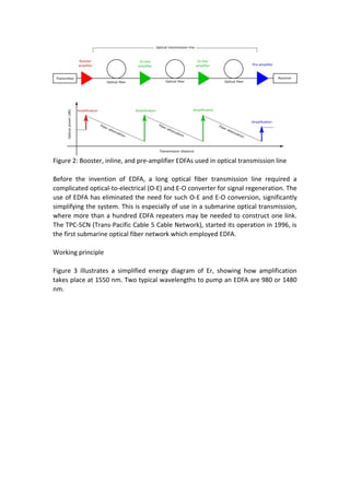
When an EDFA is pumped at 1480 nm, Er ion doped in the fiber absorbs the pump
light and is excited to an excited state (Excited state 1 in Figure 3). When sufficient
pump power is launched to the fiber and population inversion is created between
the ground state and Excited state 1, amplification by stimulated emission takes
place at around 1550 nm. When an EDFA is pumped at 980 nm, Er ion absorbs the
pump light and is excited to another excited state (Excited state 2 in Figure 3). The
lifetime of the Excited state 2 is relatively short, and as a result, the Er ion is
immediately relaxed to the Excited state 1 by radiating heat (i.e. no photon
emission). This relaxation process creates the population inversion between the
ground level and Excited state 1, and amplification takes place at around 1550 nm.
Since the first demonstration of a diode-pumped EDFA in 1989 [2], intensive effort
has been made to make the pump LD highly reliable. Now high-power pump laser
diodes at 980 nm or 1480 nm are both commercially available, and most EDFAs are
pumped by laser diodes due to the compactness and robustness.
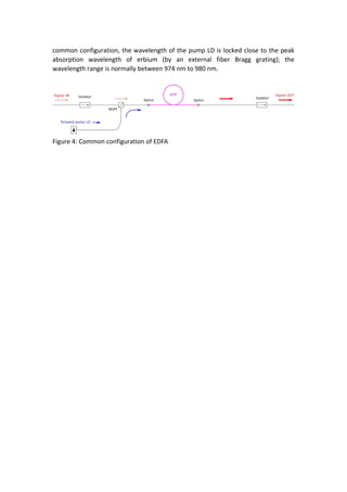
Internal configuration
Figure 4 shows one common configuration of EDFA. The input signal is combined
with the pump light by a WDM coupler and launched to the EDF. The pump light
launched to the EDF creates population inversion and the input signal is amplified by
stimulated emission. Isolators are placed both at the input and output, in order to
stabilize signal amplification by eliminating unwanted back reflection from the
output port, as well as to prevent the amplifier from operating as a laser. In this](https://image.slidesharecdn.com/edfa-190104074143/85/Erbium-Doped-Fiber-Amplifier-EDFA-3-320.jpg)

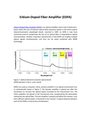
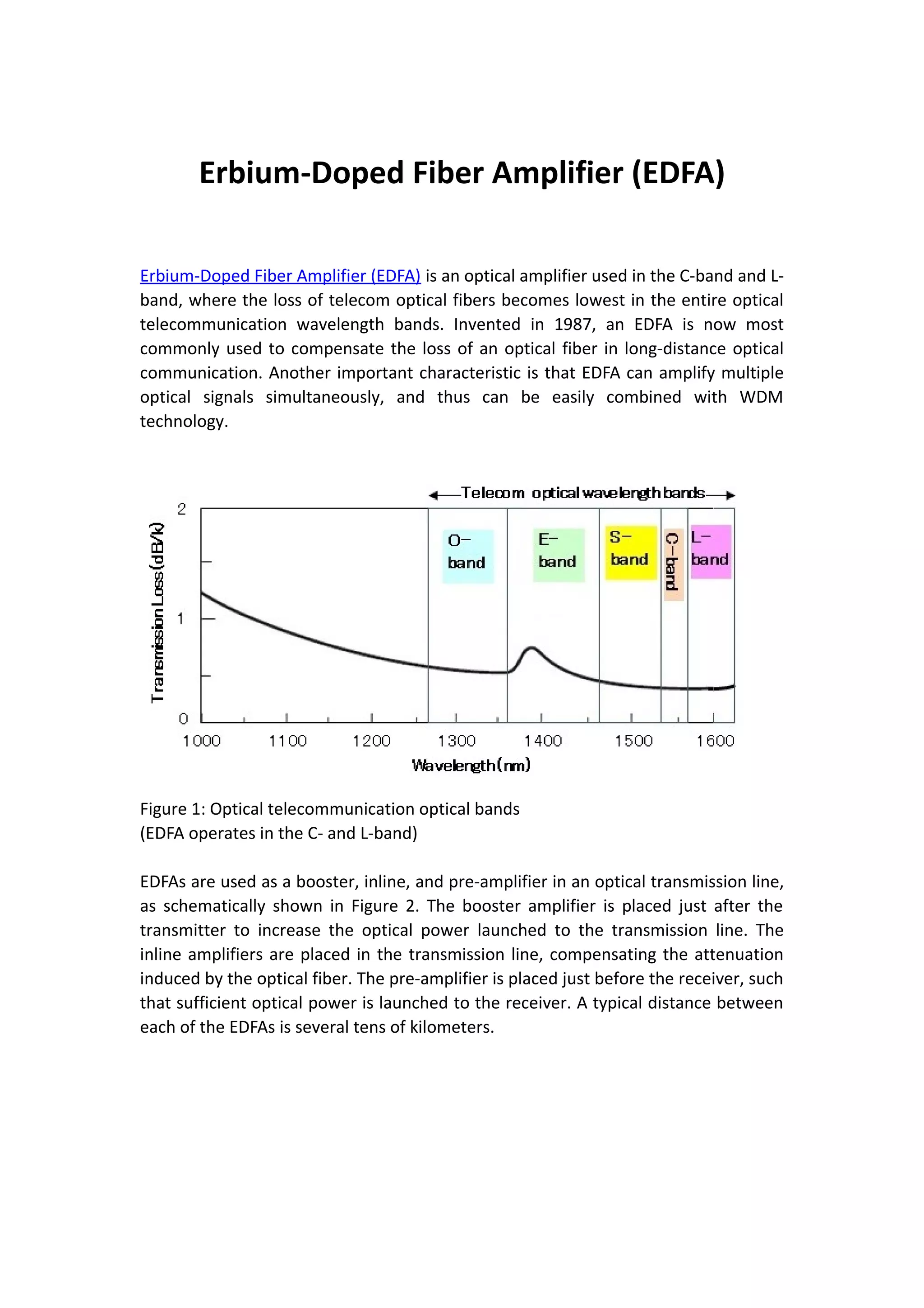
The Erbium-Doped Fiber Amplifier (EDFA) is an optical amplifier developed in 1987, primarily used in the C-band and L-band for long-distance optical communication by compensating fiber loss. EDFAs can amplify multiple signals simultaneously and are utilized as booster, inline, and pre-amplifiers in transmission lines, significantly simplifying the system compared to previous methods requiring optical-to-electrical conversions. Modern EDFAs use high-power pump laser diodes, allowing for robust operations, with configurations designed to stabilize signal amplification and optimize performance.