Downloaded 10 times
(
)(
cos)]([
)(
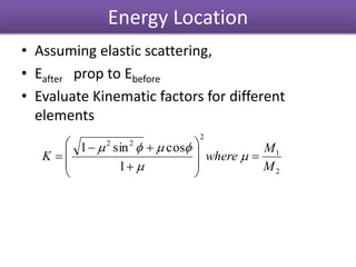
EKEKEwhere
E
E
E
Ex
y
AAAi
layers out
in
Ai
iAA
Screening Effects can be accounted
keVwhere
aE
p
EE R 4/3
21ZZ0.049
a
p
)1)(()(
For high Z elements and 2MeV beam, the deviation of cross-section
is about 2% .](https://image.slidesharecdn.com/rutherfordbackscatteringmodelingalgorithms-161204153218/85/Rutherford-Back-Scattering-RBS-Modeling-Algorithms-11-320.jpg)
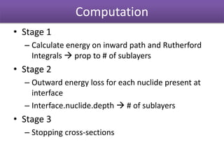
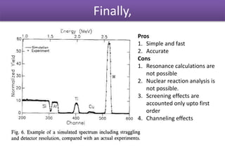


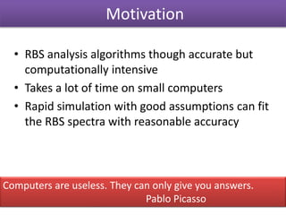
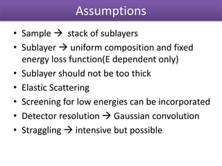
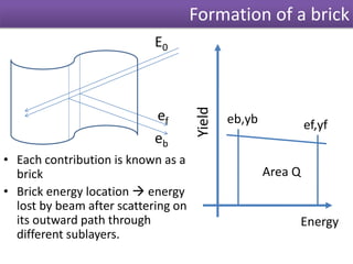
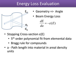
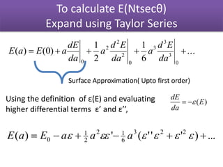
The document discusses Rutherford backscattering (RBS) modeling algorithms, focusing on efficient computation methods to analyze RBS spectra using assumptions about sample composition and energy loss. It outlines methodologies for energy loss evaluation, spectrum building, and the impact of various factors like scattering cross-sections and statistical nature of energy loss. The conclusions highlight the advantages of the proposed algorithms, such as speed and accuracy, as well as limitations regarding complex nuclear reaction analysis.


![谷歌留痕技术 [ 𝙩𝙤𝙥 𝟮𝟯𝟯. 𝙘 𝙤𝙢 ]](https://cdn.slidesharecdn.com/ss_thumbnails/top233-260130174328-3833018c-thumbnail.jpg?width=640&height=640&fit=bounds)


