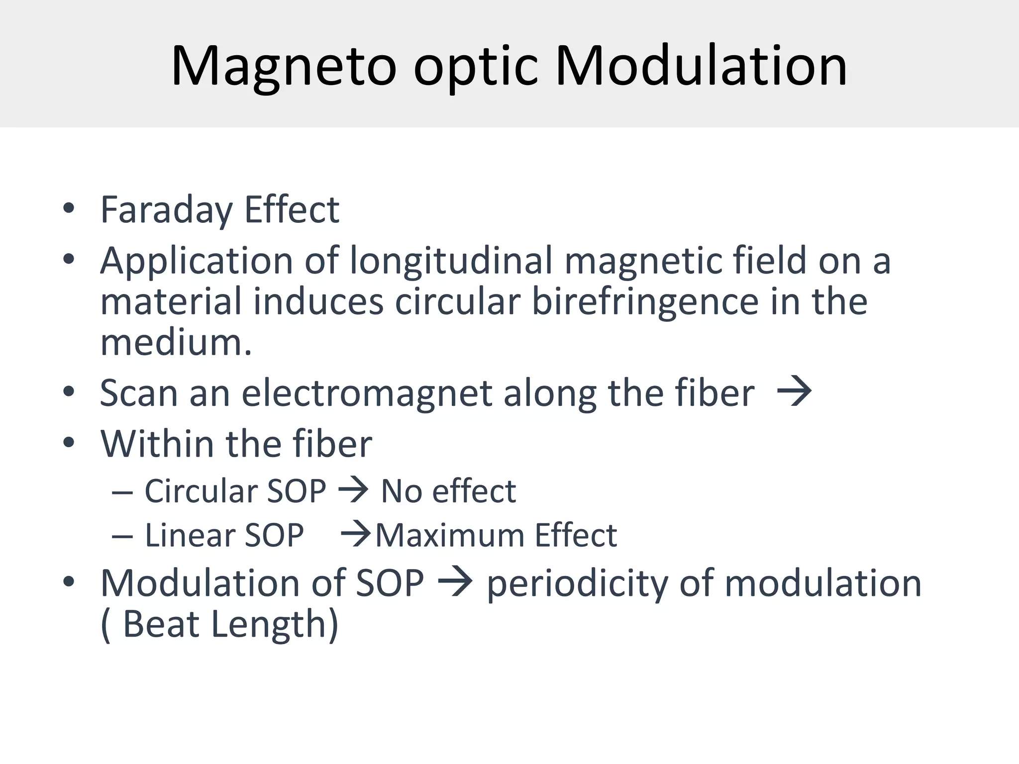
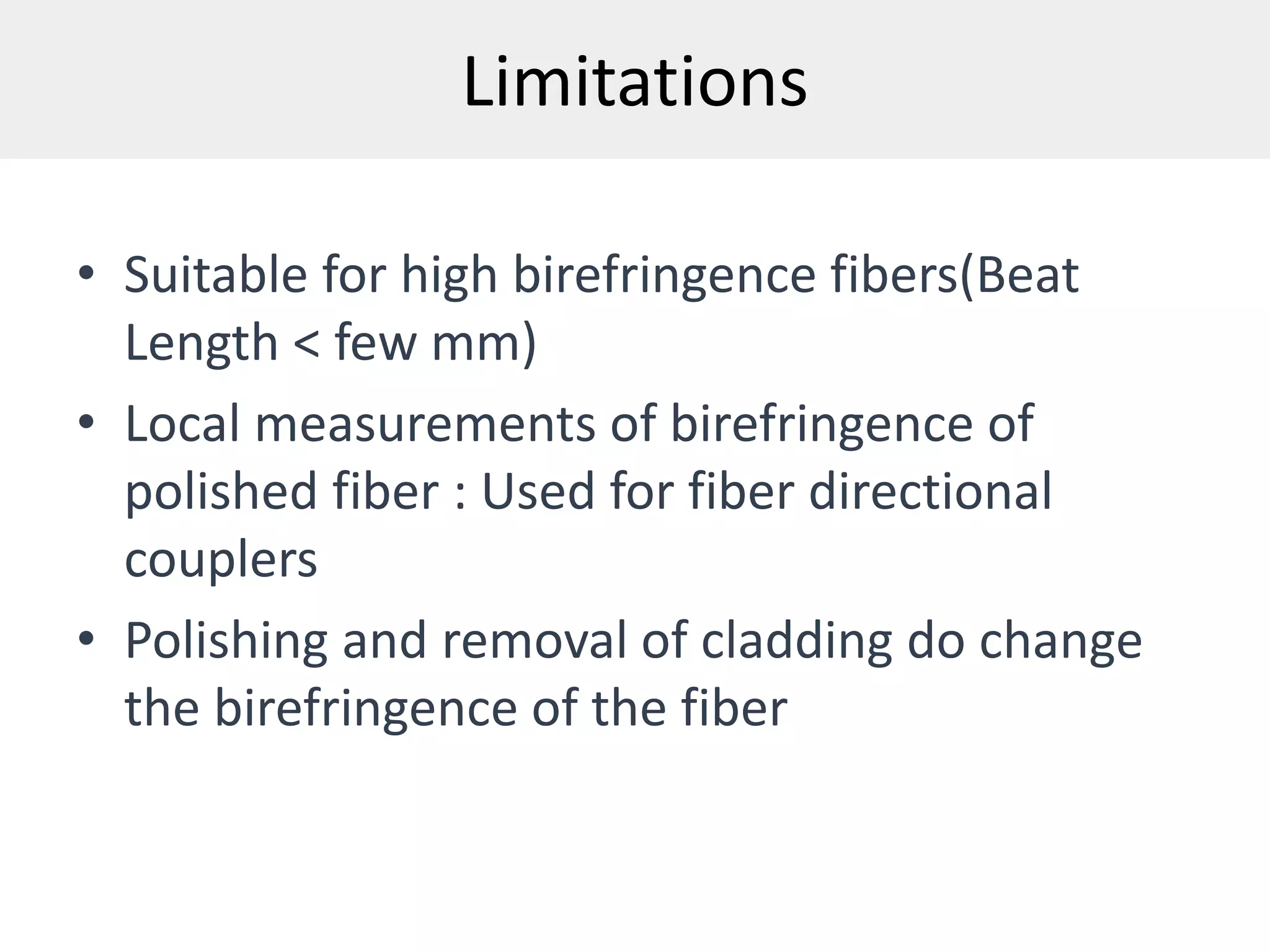
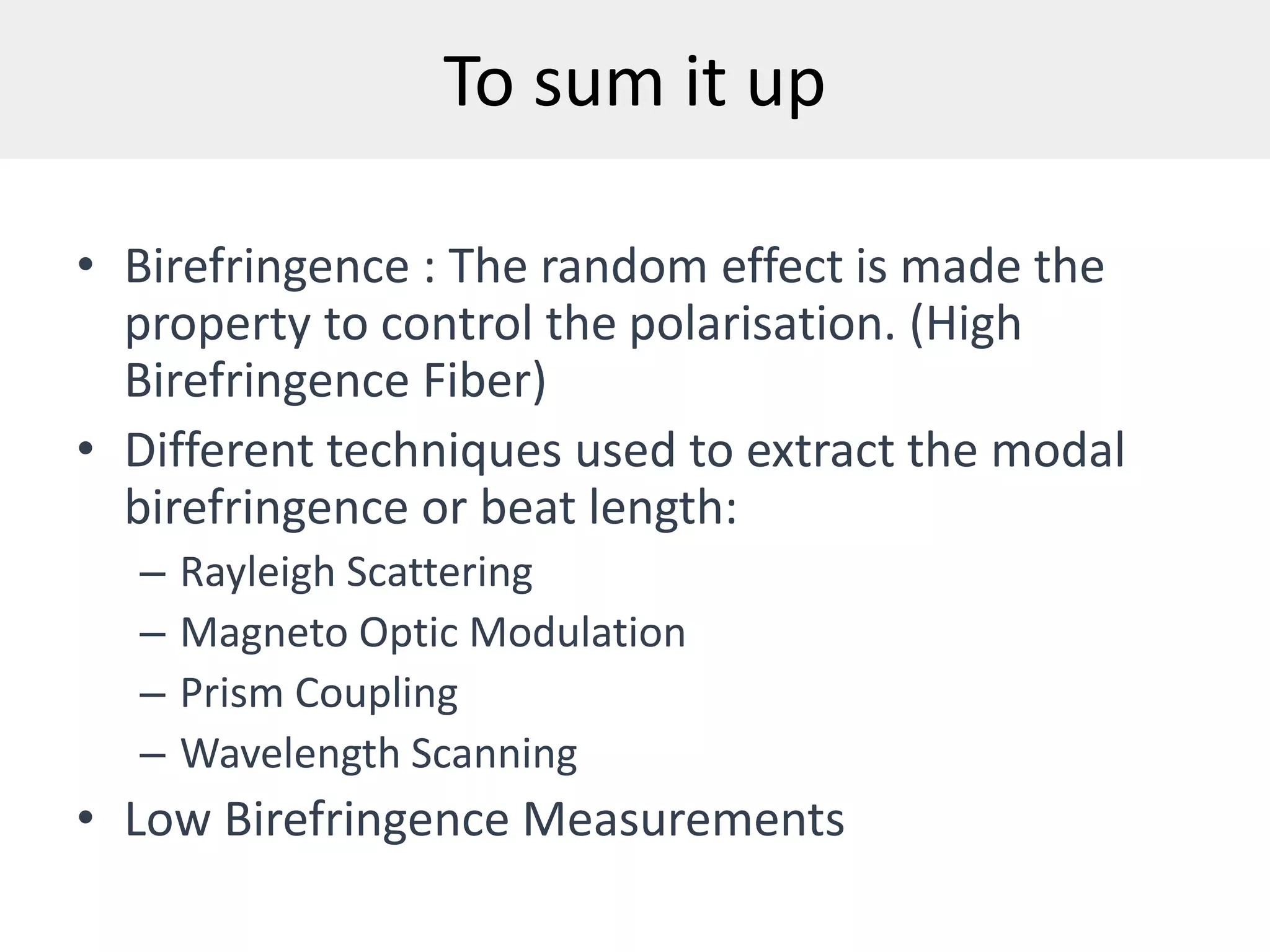
Birefringence Measurements
A Class Seminar in Fiber Optics
PHY904
Shuvan Prashant T.
Outline
• Birefringence in fibers
• Beat Length
• Rayleigh Scattering Technique
• Magneto Optic Modulation
• Prism Coupling Technique
• Wavelength Scanning
Birefringence
 Definition: Perception of two refractive indices for different
states of polarization
 Double refraction
 ∆n = ne - no
 Anisotropy, Ordinary ray, extraordinary ray
 E and D are non parallel
 Examples : uniaxial crystals
Beats
• Birefringence in fibers : difference in
propagation constants(or refractive indices)
of the orthogonal polarisation modes:
randomisation
• B = ∆n = ∆(β/k0) = (λ/2π)*∆β
• Special fibers with built-in birefringence
– Elliptic core fibers and stress induced
birefringence
• Example of Elliptic Core Fiber
Beats
z1
z3
z2
Beat Length : Distance after which SOP repeats itself
L = 2π/∆β = 4z1
Rayleigh Scattering technique
• Light gets scattered out of fiber: Rayleigh
Scattering
• Concept: For a linearly polarized light
undergoing scattering, there is no scattered
wave along the axis of the dipole along the
direction of polarization. Maximum scattering
takes place in plane perpendicular to the
direction of polarization.
Setup
Laser Polariser QWP Lens
Cladding
Mode
Stripper
Index
Matching
Liquid
Limitations
• Best Suited for highly birefringent fibers with a
beat length of few mm
• Rayleigh Scattering decreases as the fourth
order of wavelength, method is convenient to
be used in the visible region alone.
Magneto optic Modulation
• Faraday Effect
• Application of longitudinal magnetic field on a
material induces circular birefringence in the
medium.
• Scan an electromagnet along the fiber 
• Within the fiber
– Circular SOP  No effect
– Linear SOP Maximum Effect
• Modulation of SOP  periodicity of modulation
( Beat Length)
Setup
SOLENOID
QWP
LASER
SBC
LOCKIN Amplifier
QWP
POL
PD
Lens Lens
Lens
Prism Coupling Technique
• The leaky waveguide mode couples into a
prism placed just above it due to higher index
of the prism.
• Phase matching condition ensures that
direction of out coupled light is characteristic
of the propagation constant of the mode of
the waveguide.
• Different angles for modes with different
betas Modal Birefringence
Setup
θ
ψ A/
n
θ1
Limitations
• Suitable for high birefringence fibers(Beat
Length < few mm)
• Local measurements of birefringence of
polished fiber : Used for fiber directional
couplers
• Polishing and removal of cladding do change
the birefringence of the fiber
Wavelength Scanning
• High Birefringence
• Modulation of spectrum
• Spacing of modulation (∆λ)
• Beat Length = (∆λ/λ)*L
• λ Center Wavelength between
two peaks
• L Sample Length of fiber
Wavelength Dependence of Group Beat
length and birefringence
• Perform a windowed Fourier transformation
of the data to retrieve the dominant fringe
frequency around each wavelength.
• Actual period is obtained by dividing the data
spacing by the normalized frequency.
• A linear fitting of the fiber birefringence as a
function of wavelength is conducted.
Windowed Fourier Transformation of OSA trace
To sum it up
• Birefringence : The random effect is made the
property to control the polarisation. (High
Birefringence Fiber)
• Different techniques used to extract the modal
birefringence or beat length:
– Rayleigh Scattering
– Magneto Optic Modulation
– Prism Coupling
– Wavelength Scanning
• Low Birefringence Measurements
References
• Introduction to Fiber Optics, Ajoy Ghatak & K
Thyagarajan, 1st Edition, pg 441-449.
• Wavelength Scanning: “Highly Birefringent
Hollow-Core Photonic Bandgap Fiber”,
Technical Paper, Corning Inc.

Birefringence measurements

  • 1.
    Birefringence Measurements A ClassSeminar in Fiber Optics PHY904 Shuvan Prashant T.
  • 2.
    Outline • Birefringence infibers • Beat Length • Rayleigh Scattering Technique • Magneto Optic Modulation • Prism Coupling Technique • Wavelength Scanning
  • 3.
    Birefringence  Definition: Perceptionof two refractive indices for different states of polarization  Double refraction  ∆n = ne - no  Anisotropy, Ordinary ray, extraordinary ray  E and D are non parallel  Examples : uniaxial crystals
  • 4.
    Beats • Birefringence infibers : difference in propagation constants(or refractive indices) of the orthogonal polarisation modes: randomisation • B = ∆n = ∆(β/k0) = (λ/2π)*∆β • Special fibers with built-in birefringence – Elliptic core fibers and stress induced birefringence • Example of Elliptic Core Fiber
  • 5.
    Beats z1 z3 z2 Beat Length :Distance after which SOP repeats itself L = 2π/∆β = 4z1
  • 6.
    Rayleigh Scattering technique •Light gets scattered out of fiber: Rayleigh Scattering • Concept: For a linearly polarized light undergoing scattering, there is no scattered wave along the axis of the dipole along the direction of polarization. Maximum scattering takes place in plane perpendicular to the direction of polarization.
  • 7.
    Setup Laser Polariser QWPLens Cladding Mode Stripper Index Matching Liquid
  • 8.
    Limitations • Best Suitedfor highly birefringent fibers with a beat length of few mm • Rayleigh Scattering decreases as the fourth order of wavelength, method is convenient to be used in the visible region alone.
  • 9.
    Magneto optic Modulation •Faraday Effect • Application of longitudinal magnetic field on a material induces circular birefringence in the medium. • Scan an electromagnet along the fiber  • Within the fiber – Circular SOP  No effect – Linear SOP Maximum Effect • Modulation of SOP  periodicity of modulation ( Beat Length)
  • 10.
  • 11.
    Prism Coupling Technique •The leaky waveguide mode couples into a prism placed just above it due to higher index of the prism. • Phase matching condition ensures that direction of out coupled light is characteristic of the propagation constant of the mode of the waveguide. • Different angles for modes with different betas Modal Birefringence
  • 12.
  • 13.
    Limitations • Suitable forhigh birefringence fibers(Beat Length < few mm) • Local measurements of birefringence of polished fiber : Used for fiber directional couplers • Polishing and removal of cladding do change the birefringence of the fiber
  • 14.
    Wavelength Scanning • HighBirefringence • Modulation of spectrum • Spacing of modulation (∆λ) • Beat Length = (∆λ/λ)*L • λ Center Wavelength between two peaks • L Sample Length of fiber
  • 15.
    Wavelength Dependence ofGroup Beat length and birefringence • Perform a windowed Fourier transformation of the data to retrieve the dominant fringe frequency around each wavelength. • Actual period is obtained by dividing the data spacing by the normalized frequency. • A linear fitting of the fiber birefringence as a function of wavelength is conducted.
  • 16.
  • 17.
    To sum itup • Birefringence : The random effect is made the property to control the polarisation. (High Birefringence Fiber) • Different techniques used to extract the modal birefringence or beat length: – Rayleigh Scattering – Magneto Optic Modulation – Prism Coupling – Wavelength Scanning • Low Birefringence Measurements
  • 18.
    References • Introduction toFiber Optics, Ajoy Ghatak & K Thyagarajan, 1st Edition, pg 441-449. • Wavelength Scanning: “Highly Birefringent Hollow-Core Photonic Bandgap Fiber”, Technical Paper, Corning Inc.