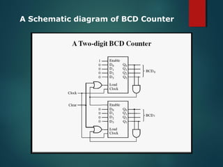
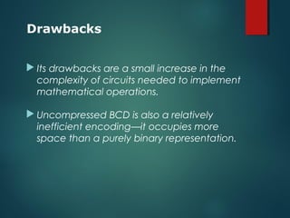
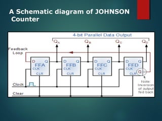
A Presentation on :
By-
MOHD BILAL
B.Tech (C.S.) II yr.
2. Synchronous counter – all state bits change under control
of a single clock
Types of Counters
1. Asynchronous (ripple) counter – changing state bits are
used as clocks to subsequent state flip-flops
3. Decade counter – counts through ten states per stage
4. Up/down counter – counts both up and down, under
command of a control input
5. Ring counter – formed by a shift register with feedback
connection in a ring
6. Johnson counter – a twisted ring counter
7. Cascaded counter
 In computing and electronic systems, binary-coded
decimal (BCD) (sometimes called natural binary-
coded decimal, NBCD) or, in its most common
modern implementation, packed decimal, is an
encoding for decimal numbers in which each digit is
represented by its own binary sequence. Its main
virtue is that it allows easy conversion to decimal digits
for printing or display, and allows faster decimal
calculations.
 In BCD, a digit is usually represented by four bits
which, in general, represent the decimal digits 0
through 9. Other bit combinations are sometimes used
for a sign or for other indications (e.g., error or
overflow).
BCD CounterBCD Counter
• To encode a decimal number using the common BCD
encoding, each decimal digit is stored in a 4-bit nibble:
• Decimal: 0 1 2 3 4 5 6 7 8 9
• BCD : 0000 0001 0010 0011 0100 0101 0110 0111 1000 1001
• Thus, the BCD encoding for the number 127 would be:
0001 0010 0111
Basics for BCDBasics for BCD
A Schematic diagram of BCD Counter
 Its drawbacks are a small increase in the
complexity of circuits needed to implement
mathematical operations.
 Uncompressed BCD is also a relatively
inefficient encoding—it occupies more
space than a purely binary representation.
Drawbacks
 Ring counters are implemented using shift
registers. It is essentially a circulating shift register
connected so that the last flip-flop shifts its value
into the first flip-flop. There is usually only a single 1
circulating in the register, as long as clock pulses
are applied.
Start control signal, which presets the
left-most flip-flop to 1 and clears the
others to 0.
An n-bit Ring Counter
The Johnson counter, also known as the
twisted-ring counter, is exactly the same as
the ring counter except that the inverted
output of the last flip-flop is connected to the
input of the first flip-flop.
Let’s say, starts from 000, 100, 110, 111, 011
and 001, and the sequence is repeated so
long as there is input pulse.
A Schematic diagram of JOHNSON
Counter
Clock Pulse No FFA FFB FFC FFD
0 0 0 0 0
1 1 0 0 0
2 1 1 0 0
3 1 1 1 0
4 1 1 1 1
5 0 1 1 1
6 0 0 1 1
7 0 0 0 1
Truth Table for JOHNSON
Counter
To initialize the operation of the Johnson counter, it
is necessary to reset all flip-flops, as shown in the
figure. Observe that neither the Johnson nor the ring
counter will generate the desired counting sequence
if not initialized properly.
• Digital Electronics BookDigital Electronics Book
• Net Surfing :-Net Surfing :-
• http://www.electronics-tutorials.ws
• http://www.doc.ic.ac.uk/~nd/surprise_96/journal/v
ol4/cwl3/report.html#bcd
Counters

Counters

  • 1.
    A Presentation on: By- MOHD BILAL B.Tech (C.S.) II yr.
  • 3.
    2. Synchronous counter– all state bits change under control of a single clock Types of Counters 1. Asynchronous (ripple) counter – changing state bits are used as clocks to subsequent state flip-flops 3. Decade counter – counts through ten states per stage 4. Up/down counter – counts both up and down, under command of a control input 5. Ring counter – formed by a shift register with feedback connection in a ring 6. Johnson counter – a twisted ring counter 7. Cascaded counter
  • 5.
     In computingand electronic systems, binary-coded decimal (BCD) (sometimes called natural binary- coded decimal, NBCD) or, in its most common modern implementation, packed decimal, is an encoding for decimal numbers in which each digit is represented by its own binary sequence. Its main virtue is that it allows easy conversion to decimal digits for printing or display, and allows faster decimal calculations.  In BCD, a digit is usually represented by four bits which, in general, represent the decimal digits 0 through 9. Other bit combinations are sometimes used for a sign or for other indications (e.g., error or overflow). BCD CounterBCD Counter
  • 6.
    • To encodea decimal number using the common BCD encoding, each decimal digit is stored in a 4-bit nibble: • Decimal: 0 1 2 3 4 5 6 7 8 9 • BCD : 0000 0001 0010 0011 0100 0101 0110 0111 1000 1001 • Thus, the BCD encoding for the number 127 would be: 0001 0010 0111 Basics for BCDBasics for BCD
  • 7.
    A Schematic diagramof BCD Counter
  • 8.
     Its drawbacksare a small increase in the complexity of circuits needed to implement mathematical operations.  Uncompressed BCD is also a relatively inefficient encoding—it occupies more space than a purely binary representation. Drawbacks
  • 9.
     Ring countersare implemented using shift registers. It is essentially a circulating shift register connected so that the last flip-flop shifts its value into the first flip-flop. There is usually only a single 1 circulating in the register, as long as clock pulses are applied.
  • 10.
    Start control signal,which presets the left-most flip-flop to 1 and clears the others to 0. An n-bit Ring Counter
  • 12.
    The Johnson counter,also known as the twisted-ring counter, is exactly the same as the ring counter except that the inverted output of the last flip-flop is connected to the input of the first flip-flop. Let’s say, starts from 000, 100, 110, 111, 011 and 001, and the sequence is repeated so long as there is input pulse.
  • 13.
    A Schematic diagramof JOHNSON Counter
  • 14.
    Clock Pulse NoFFA FFB FFC FFD 0 0 0 0 0 1 1 0 0 0 2 1 1 0 0 3 1 1 1 0 4 1 1 1 1 5 0 1 1 1 6 0 0 1 1 7 0 0 0 1 Truth Table for JOHNSON Counter
  • 15.
    To initialize theoperation of the Johnson counter, it is necessary to reset all flip-flops, as shown in the figure. Observe that neither the Johnson nor the ring counter will generate the desired counting sequence if not initialized properly.
  • 16.
    • Digital ElectronicsBookDigital Electronics Book • Net Surfing :-Net Surfing :- • http://www.electronics-tutorials.ws • http://www.doc.ic.ac.uk/~nd/surprise_96/journal/v ol4/cwl3/report.html#bcd

Editor's Notes

  • #3 All Editing, Designing and Animations done by M.BILAL
  • #4 All Editing, Designing and Animations done by M.BILAL
  • #5 All Editing, Designing and Animations done by M.BILAL