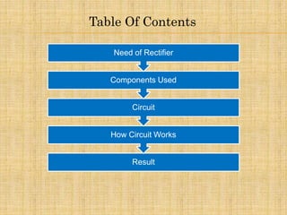
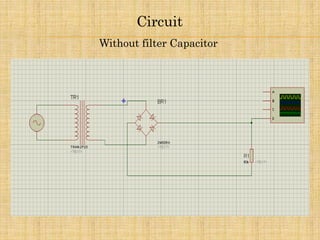
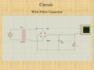
Topic : Full Wave Bridge Rectifier
(Simulation Model) Filter /Without Filter
Submitted to: Ravindra Meena Sir
( HOD Electrical dept.)
Submitted by : Jaspreet Singh
Ruchit Porwal
Adhiraj Singh
Electrical
Major Assignment
Table Of Contents
Result
How Circuit Works
Circuit
Components Used
Need of Rectifier
Need of Rectifiers
•Rectifier is used to convert AC signal to DC signal
•Almost all the electronic devices such as diodes, transistors, ICs, etc. Require
DC voltage for their proper operation
•It can be used as a substitute for source of DC voltage
•It is used in high current power supplies
•It is used in power supplies for many electronc circuits
Components Used
AC voltage source: 230V,
50Hz
Diodes: 4 - IN4007
Resistor: 10k ohms
Oscilloscope
Capacitor: 500 micro farads
Sinusoidal Voltage Source
The sine wave or sinusoid is a mathematical curve that describes a smooth
repetitive oscillation. It is named after the function sine, of which it is
the graph. It occurs often in pure and applied mathematics, as well
as physics,engineering, signal processing and many other fields.
Diodes
In electronics, a diode is a two-terminal electronic component that
conducts primarily in one direction , it has low (ideally
zero)resistance to the flow of current in one direction, and high
(ideally infinite) resistance in the other.
Resistors
A resistor is a passive two-terminal electrical component that
implements electrical resistance as a circuit element. Resistors may be used
to reduce current flow, and, at the same time, may act to lower voltage levels
within circuits
Oscilloscope
An oscilloscope, previously called an oscillograph, CRO (for
cathode-ray oscilloscope), is a type of electronic test instrument that
allows observation of constantly varying signal voltages, usually as a
two-dimensional plot of one or more signals as a function of time.
Other signals (such as sound or vibration) can be converted to
voltages and displayed.
Circuit
Without filter Capacitor
With Filter Capacitor
Circuit
How Circuit Works
When we run the simulation, only 2 diodes will conduct in each half cycle
and will give rise to a voltage waveform which doesn’t contains any
negative half of the original sinusoidal waveform.
After measuring using a probe, the rms voltage across the resistor is found
to be 6.88V. So 10V signal is converted to 6.88V signal without having
any negative cycle. Rest of the voltage i.e. (10-6.88) = 3.12V is the
voltage drop across the diodes. Voltage drop across each diode is 1.56V.
But in practical dc application, we can’t use a DC with such a
heavy ripples. So to reduce theripples, we can make use of capacitors.
(Without capacitor filter)
Results
(With capacitor filter)
Results
Conclusion
•In full wave bridge rectifier circuit when capacitor filter
is used then it reduce the current ripple in the output of
the rectifier which is not seen in the full wave bridge
rectifier circuit without filter.
•While when capacitor filter is not used then the full
wave bridge rectifier just acts as a normal rectifier giving
a complete positive output source of the given wave
form, converting negative half cycle to positive.
Full Wave Bridge Rectifier simulation (with/without filter capacitor)

Full Wave Bridge Rectifier simulation (with/without filter capacitor)

  • 1.
    Topic : FullWave Bridge Rectifier (Simulation Model) Filter /Without Filter Submitted to: Ravindra Meena Sir ( HOD Electrical dept.) Submitted by : Jaspreet Singh Ruchit Porwal Adhiraj Singh Electrical Major Assignment
  • 2.
    Table Of Contents Result HowCircuit Works Circuit Components Used Need of Rectifier
  • 3.
    Need of Rectifiers •Rectifieris used to convert AC signal to DC signal •Almost all the electronic devices such as diodes, transistors, ICs, etc. Require DC voltage for their proper operation •It can be used as a substitute for source of DC voltage •It is used in high current power supplies •It is used in power supplies for many electronc circuits
  • 4.
    Components Used AC voltagesource: 230V, 50Hz Diodes: 4 - IN4007 Resistor: 10k ohms Oscilloscope Capacitor: 500 micro farads
  • 5.
    Sinusoidal Voltage Source Thesine wave or sinusoid is a mathematical curve that describes a smooth repetitive oscillation. It is named after the function sine, of which it is the graph. It occurs often in pure and applied mathematics, as well as physics,engineering, signal processing and many other fields.
  • 6.
    Diodes In electronics, adiode is a two-terminal electronic component that conducts primarily in one direction , it has low (ideally zero)resistance to the flow of current in one direction, and high (ideally infinite) resistance in the other.
  • 7.
    Resistors A resistor isa passive two-terminal electrical component that implements electrical resistance as a circuit element. Resistors may be used to reduce current flow, and, at the same time, may act to lower voltage levels within circuits
  • 8.
    Oscilloscope An oscilloscope, previouslycalled an oscillograph, CRO (for cathode-ray oscilloscope), is a type of electronic test instrument that allows observation of constantly varying signal voltages, usually as a two-dimensional plot of one or more signals as a function of time. Other signals (such as sound or vibration) can be converted to voltages and displayed.
  • 9.
  • 10.
  • 11.
    How Circuit Works Whenwe run the simulation, only 2 diodes will conduct in each half cycle and will give rise to a voltage waveform which doesn’t contains any negative half of the original sinusoidal waveform. After measuring using a probe, the rms voltage across the resistor is found to be 6.88V. So 10V signal is converted to 6.88V signal without having any negative cycle. Rest of the voltage i.e. (10-6.88) = 3.12V is the voltage drop across the diodes. Voltage drop across each diode is 1.56V. But in practical dc application, we can’t use a DC with such a heavy ripples. So to reduce theripples, we can make use of capacitors.
  • 12.
  • 13.
  • 14.
    Conclusion •In full wavebridge rectifier circuit when capacitor filter is used then it reduce the current ripple in the output of the rectifier which is not seen in the full wave bridge rectifier circuit without filter. •While when capacitor filter is not used then the full wave bridge rectifier just acts as a normal rectifier giving a complete positive output source of the given wave form, converting negative half cycle to positive.